EP0525732A1 - Verfahren und Vorrichtung zur Überprüfung des Abnutzungsgrades des Deckgewebes eines Antriebsriemens - Google Patents
Verfahren und Vorrichtung zur Überprüfung des Abnutzungsgrades des Deckgewebes eines Antriebsriemens Download PDFInfo
- Publication number
- EP0525732A1 EP0525732A1 EP92112888A EP92112888A EP0525732A1 EP 0525732 A1 EP0525732 A1 EP 0525732A1 EP 92112888 A EP92112888 A EP 92112888A EP 92112888 A EP92112888 A EP 92112888A EP 0525732 A1 EP0525732 A1 EP 0525732A1
- Authority
- EP
- European Patent Office
- Prior art keywords
- belt
- value
- electric
- signalling
- pole
- Prior art date
- Legal status (The legal status is an assumption and is not a legal conclusion. Google has not performed a legal analysis and makes no representation as to the accuracy of the status listed.)
- Granted
Links
- 239000004744 fabric Substances 0.000 title claims abstract description 34
- 238000000034 method Methods 0.000 title claims description 16
- 230000011664 signaling Effects 0.000 claims abstract description 40
- 238000001514 detection method Methods 0.000 claims abstract description 3
- 230000000875 corresponding effect Effects 0.000 claims description 14
- 239000000523 sample Substances 0.000 claims description 7
- 230000033001 locomotion Effects 0.000 claims description 6
- 238000011144 upstream manufacturing Methods 0.000 claims description 5
- 238000001816 cooling Methods 0.000 claims description 4
- 230000004913 activation Effects 0.000 claims description 3
- 230000002596 correlated effect Effects 0.000 claims description 2
- 230000005764 inhibitory process Effects 0.000 claims description 2
- 239000011248 coating agent Substances 0.000 description 4
- 238000000576 coating method Methods 0.000 description 4
- 229920000642 polymer Polymers 0.000 description 4
- 230000000694 effects Effects 0.000 description 3
- 238000007689 inspection Methods 0.000 description 3
- 230000000750 progressive effect Effects 0.000 description 3
- 238000009825 accumulation Methods 0.000 description 2
- 229920005601 base polymer Polymers 0.000 description 2
- 230000005540 biological transmission Effects 0.000 description 2
- 239000006229 carbon black Substances 0.000 description 2
- 150000001875 compounds Chemical class 0.000 description 2
- 238000005259 measurement Methods 0.000 description 2
- 230000003014 reinforcing effect Effects 0.000 description 2
- 239000004753 textile Substances 0.000 description 2
- OKTJSMMVPCPJKN-UHFFFAOYSA-N Carbon Chemical compound [C] OKTJSMMVPCPJKN-UHFFFAOYSA-N 0.000 description 1
- 229920002302 Nylon 6,6 Polymers 0.000 description 1
- 230000002547 anomalous effect Effects 0.000 description 1
- 230000008859 change Effects 0.000 description 1
- 238000010586 diagram Methods 0.000 description 1
- 238000006073 displacement reaction Methods 0.000 description 1
- 239000011152 fibreglass Substances 0.000 description 1
- 230000005669 field effect Effects 0.000 description 1
- 230000004907 flux Effects 0.000 description 1
- 229910002804 graphite Inorganic materials 0.000 description 1
- 239000010439 graphite Substances 0.000 description 1
- 238000005304 joining Methods 0.000 description 1
- 238000004519 manufacturing process Methods 0.000 description 1
- 230000007246 mechanism Effects 0.000 description 1
- 239000002184 metal Substances 0.000 description 1
- 239000000203 mixture Substances 0.000 description 1
- 238000012986 modification Methods 0.000 description 1
- 230000004048 modification Effects 0.000 description 1
- 229920001084 poly(chloroprene) Polymers 0.000 description 1
- 230000006641 stabilisation Effects 0.000 description 1
- 238000011105 stabilization Methods 0.000 description 1
- 238000003860 storage Methods 0.000 description 1
- 239000000126 substance Substances 0.000 description 1
Images

Classifications
-
- G—PHYSICS
- G01—MEASURING; TESTING
- G01N—INVESTIGATING OR ANALYSING MATERIALS BY DETERMINING THEIR CHEMICAL OR PHYSICAL PROPERTIES
- G01N27/00—Investigating or analysing materials by the use of electric, electrochemical, or magnetic means
- G01N27/02—Investigating or analysing materials by the use of electric, electrochemical, or magnetic means by investigating impedance
- G01N27/04—Investigating or analysing materials by the use of electric, electrochemical, or magnetic means by investigating impedance by investigating resistance
- G01N27/20—Investigating the presence of flaws
-
- G—PHYSICS
- G01—MEASURING; TESTING
- G01N—INVESTIGATING OR ANALYSING MATERIALS BY DETERMINING THEIR CHEMICAL OR PHYSICAL PROPERTIES
- G01N3/00—Investigating strength properties of solid materials by application of mechanical stress
- G01N3/56—Investigating resistance to wear or abrasion
-
- G—PHYSICS
- G01—MEASURING; TESTING
- G01R—MEASURING ELECTRIC VARIABLES; MEASURING MAGNETIC VARIABLES
- G01R27/00—Arrangements for measuring resistance, reactance, impedance, or electric characteristics derived therefrom
- G01R27/02—Measuring real or complex resistance, reactance, impedance, or other two-pole characteristics derived therefrom, e.g. time constant
- G01R27/025—Measuring very high resistances, e.g. isolation resistances, i.e. megohm-meters
-
- G—PHYSICS
- G01—MEASURING; TESTING
- G01N—INVESTIGATING OR ANALYSING MATERIALS BY DETERMINING THEIR CHEMICAL OR PHYSICAL PROPERTIES
- G01N2203/00—Investigating strength properties of solid materials by application of mechanical stress
- G01N2203/02—Details not specific for a particular testing method
- G01N2203/022—Environment of the test
- G01N2203/0222—Temperature
Definitions
- the present invention relates to a method and apparatus to check the state of wear in a coating fabric of a driving belt.
- Belts are usually comprised of an elastomeric body and a coating fabric applied to at least one of the belt surfaces designed to come into contact with the active surfaces of the belt pulleys.
- this fabric is provided to coat the belt toothing designed to mesh with the pulley teeth.
- the applicant has developed a method and apparatus capable of checking the acceptability of the state of wear of the coating fabric in a driving belt in a completely automatic manner.
- this method and apparatus being the object of the European Patent Application No. 91830544.2, disclose the use of a driving belt, a toothed belt for example, provided with a reinforcing textile cover applied to the work surface acting in contact with the pulleys.
- the covering fabric is treated with electrically conductive charges so that, by applying an electric voltage between two pulleys engaging the belt which are electrically insulated from each other, it is possible to detect the resistance offered to the passage of current by at least two belt branches kept taut between said pulleys.
- the belt use brings about the progressive consumption of the electrically conductive charges of the covering fabric and, consequently, the progressive increase in the detectable resistance value, so that, based on the detected resistance value, it is possible to go back to the state of wear of the belt fabric.
- the resistance value detected on the belt is provided to be compared with a previously input resistance value corresponding to a given state of wear of the belt fabric.
- said signalling need to be conveniently inhibited during the belt operation as well as over a predetermined period of time referred to as waiting time included between the moment at which the belt operation is interrupted and the moment at which the measurement of a parameter selected from the electric resistance of the fabric and the temperature on said fabric, takes a constant value; in this way the operation of the checking apparatus is not affected by anomalous conditions that have been deemed to consist for example in the presence of electrostatic charges on one or more of the pulleys and/or the presence of high temperatures on the belt and in the vicinity of the belt.
- the invention relates to a method for checking the state of wear of the covering fabric in a driving belt applied to a motor, in which said driving belt, provided with a covering fabric treated with electrically conductive charges acting in contact relationship with at least first and second pulleys electrically insulated from each other and the setting in rotation of which brings about the operation of the belt itself, is submitted to the following steps:
- the danger signalling enabling step is preferably carried out through inhibition of said disabling step, at least over a predetermined delay time starting from the moment at which the predetermined electric voltage applying step is activated.
- the waiting time is preset by chronometric detection of the time elapsing from the moment at which the belt operation is stopped to the moment at which the resistance offered by said belt branches takes a substantially constant value.
- an apparatus for checking the state of wear of a driving belt fabric which comprises:
- the signalling means is comprised of a diode having one pole connected to said comparing means and a second pole connected to an auxiliary electric circuit branch to be fed concurrently with the application of electric voltage to said pulleys and carrying said disabling means, said diode being arranged to emit the danger signalling when on one of the two poles, selectively predetermined, an electric signal of higher value than the electric signal existing on the other pole is present.
- the comparing means preferably comprises at least one comparator-inverter having one input pole arranged to receive an input signal correlated with the resistance value detected on the belt branches, a second input pole arranged to receive a reference signal corresponding to the predetermined resistance value and an output pole arranged to send an output signal to the signalling means when the first input signal has a lower value than the first reference signal.
- the disabling means comprises a second comparator-inverter acting on the auxiliary circuit branch and having one input pole arranged to receive an input signal, a second input pole arranged to receive a reference signal and an output pole connected to said diode for interrupting the enabling signal when the input signal overcomes the reference signal value, at least a primary timer designed to emit the input signal depending on the duration of the waiting time from the moment at which the electric power in the auxiliary circuit branch is cut off operating upstream of said first input pole.
- Said disabling means may also be comprised of at least a thermostatic probe to be positioned on the driving belt fabric and connected to the auxiliary circuit branch in order to send an electric disabling signal to the second pole of the diode when the temperature on the belt overcomes a predetermined value.
- one of said pulleys is arranged to operate a cooling pump in a motor-vehicle engine, said pump being electrically insulated from said engine.
- an apparatus for checking the state of wear of a driving belt in accordance with the present invention has been generally identified by reference numeral 1.
- Apparatus 1 provides for the use of a driving belt 2 operatively engaged to one or more first pulleys 3a, 3b and at least a second pulley 4 electrically insulated from the first pulleys 3.
- the belt 2 is installed on a motor-vehicle engine and the first pulleys 3a, 3b are respectively connected to the crankshaft and alternator belonging to said engine.
- the second pulley 4 is advantageously arranged to operate a cooling pump 5, usually provided in the engine and electrically insulated from the engine block 6 upon interposition of one or more gaskets 7.
- the belt 2 which can be either of the trapezoidal, or “flat” or “poly-V” type, or, as in the embodiment shown, a toothed belt, is provided, on a work surface 2a thereof, with at least a textile covering fabric treated with electrically conductive charges, acting in contact relationship with the pulleys 3a, 3b and 4.
- This fabric is not shown in the accompanying drawings and will not be further described as widely discussed in the European Patent Application No. 91830544.2, in the name of the same Applicant.
- the presence of the fabric treated with electrically conductive charges gives the belt 2 a predetermined electric resistance that will tend to progressively increase as the belt is used in time, due to the progressive consumption of the covering fabric.
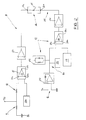
- the belt 2 is further associated with an electronic control unit generally identified by 8 in Fig. 1 which is comprised, as better shown in Fig. 2, of an electric circuit 9 the respective poles 9a, 9b of which are connected to one of the first pulleys 3a and the second pulley 4 in order to apply a predetermined electric voltage to at least two belt branches, denoted by A and B in Fig. 1 and included between the pulleys.
- an electronic control unit generally identified by 8 in Fig. 1 which is comprised, as better shown in Fig. 2, of an electric circuit 9 the respective poles 9a, 9b of which are connected to one of the first pulleys 3a and the second pulley 4 in order to apply a predetermined electric voltage to at least two belt branches, denoted by A and B in Fig. 1 and included between the pulleys.
- Pulley 3a is earthed.
- the two belt branches A, B as regards the current passage behave like two resistances connected in parallel, the effects of which give rise to an overall resistance denoted Rx in Fig. 2 from the value of which it is possible to go back to the belt state of wear.
- detecting means 10 designed to detect the resistance Rx value offered by the belt 2, combined with comparing means 11 designed to compare the resistance Rx value with a preset resistance value corresponding to a predetermined wear degree of the belt 2.
- the comparing means 11 preferably consists of a comparator-inverter 12, of the FET (field-effect transistor) type, having one input pole 12a connected to the detecting means 10 which is essentially comprised of a connecting circuit branch passed through by a current flux proportional to the resistance Rx value offered by the belt 2.
- the comparator-inverter 12 also has a second input pole 12b, to which an electric signal of a predetermined value is input through one additional feed unit 10a, which predetermined value corresponds to the preset resistance value, as well as an output pole 12c arranged to emit an electric output signal when the input signal coming from the connecting branch 10 is lower than the reference signal input to the second input pole 12b.
- the output signal coming from the comparator-inverter 12, previously amplified by an amplifying signal 13, is sent to signalling means 14 preferably comprising at least a light emitting diode 15 having one pole 15a connected to the first comparator-inverter 12 and a second pole 15b terminating at an auxiliary electric circuit branch 16 to be fed concurrently with the application of electric voltage to pulleys 3a and 4.
- the diode 15 enables the passage of current only when a situation occurs in which in one of its poles and more particularly the second pole 15b, an electric signal is present, concurrently with the absence of the electric signal on the other pole 15a.
- disabling means 17 acts on the auxiliary circuit branch 16 which, as better clarified in the following, is arranged to deactivate the signalling means 15 while the driving belt 2 is in operation and also for a preset waiting time, preferably included between two and six minutes, starting from the moment at which the belt operation is stopped.
- the waiting time can vary depending upon the belt type and features and the features of the engine to which the belt is applied.
- the disabling means 17 is preferably comprised of a second comparator-inverter 18, quite similar to the first comparator-inverter 12, having one input pole 18a arranged to receive an electric input signal following from the auxiliary circuit branch 16 feeding, as well as a second input pole 18b designed to receive a reference signal coming from a second additional feed unit 19.
- the second comparator-inverter 18 finally has an output pole 18c designed to emit an electric enabling signal only when the signal coming from the first input pole 18a has a lower value than the reference signal sent to the second input pole 18b.
- the enabling signal will reach the second pole 15b of the diode 15 upon passing through a second signal amplifier 20.
- the second comparator-inverter 18 acts in such a manner that the enabling signal is interrupted when the input signal reaching the first input pole 18a exceeds the value of the reference signal input to the second input pole 18b.
- a primary timer 21 consisting for example of a mere "RC" circuit connected to the first input pole 18a and designed to emit the input signal according to the duration of the desired waiting time, for example approximately three minutes from the moment at which the application of electric voltage to the pulleys 3a, 4 is interrupted, being consequently also interrupted the power supply to the auxiliary circuit branch 16.
- At least a delay timer 22 is provided upstream of the primary timer 21 and it is designed to cause the feeding of the input signal to the first input pole 18a of the second comparator- invertor 18, at least for a predetermined delay time preferably corresponding to 0.2 seconds and at all events included between 0.1 and 0.4 seconds for example.
- Said thermal probe will be positioned on the belt 2 fabric and operatively connected to the first input pole 18a of the second comparator-inverter 18 in order to infeed the input signal when the temperature close to the belt overcomes a predetermined limit value.
- This thermal probe can consist of a NTC (Negative Temperature Coefficient)-type device for example, not further described as known per se.
- NTC Negative Temperature Coefficient
- the voltage drop produced by the passage of current through the resistance Rx causes an input signal of low value to reach the first input pole 12a of the first comparator-inverter 12, which low value is lower than the reference signal value sent to the second input pole 12b.
- the comparator-inverter 12 operating according to the Boolean logic sends an electric signal of high value to the first pole 15a of diode 15.
- the diode 15 will not be able to emit any signalling independently of whether there is an electric signal at the second pole 15b or not.
- the power supply to the auxiliary circuit 16 occurs.
- the signal input to said circuit after passing through the delay timer 22 reaches the first pole 18a of the second comparator-inverter 18 that, in this case too due to the principle of the Boolean logic, will send a low value signal to the second pole 15b of the diode 15, in that the signal on the first input pole 18a is higher than the reference signal present on the second input pole 18b.
- the enabling signal to the signalling means 14 is interrupted and this condition will remain unchanged until the interruption of the electric supply to the circuit 9 and auxiliary circuit branch 16 is carried out at least for the preset waiting time.
- the primary timer 21 is also loaded, which will cause the storage of the waiting time thereinto.
- the belt inspection is carried out by interrupting the operation of said belt together with the power supply to the electric circuit 9 and auxiliary circuit branch 16 and waiting for the end of the preset waiting time, in order to subsequently apply voltage again to the circuit 9 and auxiliary branch 16.
- the diode 15 will not be able to emit any danger signalling in that the primary timer 21, and the thermal probe 23 if present, will go on feeding the first input pole 18a of the second comparator-inverter 18 keeping the activation signal of the second pole 15b of the diode itself interrupted.
- diode 15 may erroneously emit a danger signalling when the fictitious value of resistance Rx, in spite of the operation being stopped, can be affected by the presence of electrostatic residual charges on the second pulley 4, as well as by the high temperature present in the vicinity of the belt 2.
- the belt immediately after being stopped exhibits high resistance values, in the order of 1.6 to 2 MQ, and it is therefore necessary to wait for a certain lapse of time before the insulated pulley 4 may completely discharge to earth and the temperature in the vicinity of the belt 2 may reach a sufficiently low value.
- This waiting time can be input by chronometric measurement of the time elapsing from the stopping of the belt operation to the moment at which the resistance Rx offered by the belt itself reaches a substantially constant value.
- the decay of the resistance Rx value in time is shown by way of example in the graph of Fig. 4 reproducing the resistance Rx value on the ordinates and the time elapsing from the stopping of the belt 2 operation on the abscissas.
- the second comparator-inverter 18 When the application of electric voltage to the circuit 9 and auxiliary branch 16 occurs after a longer time than the waiting time, the second comparator-inverter 18 within the time permitted by the delay timer 22 emits the enabling signal from the output pole 18c in that the reference signal from the second input pole 18b will be higher than the signal present on the first input pole 18a.
- the diode 15 therefore will be in a position to be switched on so as to emit the danger signalling if, in the presence of a high resistance value offered by the belt, there is no signal on the first pole 15a of the diode itself.
- the waiting time will be computed for each belt after establishing the motor to which the belt is applied for motion transmission.
- the belt In order to establish the waiting time, the belt is kept in rotation being subjected to torque and rated revolutions over a predetermined period of time that could be included between 0 and 1000 hours for example.
- the predetermined time takes lower or higher values depending on whether it refers to a new belt or a belt that has been used for a long time respectively.
- the resistance values are low and therefore can be less affected by temperature than those relating to a belt that has been running for a long time.
- the graph in Fig. 4 refers to a toothed belt having the following features:
- two electrically conductive polychloroprene polymer-based layers containing conductive charges are applied to the reinforcing fabric.
- the conductive charges preferably consist of a conductive black known as "carbon black” and the charges can have sizes of 200 A (Angstrom).
- the layer disposed towards the belt body is formed with a compound mainly containing carbon black (50 parts by 100 parts of polymer).
- the external layer corresponding to the work surface is in turn formed with a compound mainly containing self-lubricating graphite (60 parts by 100 parts of polymer).
- the engine is a four-cylinders with camshaft on top, piston displacement 1.4 litres and 5,500 peak r.p.m.
- the waiting time of 3 minutes has been computed by rotating the belt for 300 hours at a torque of 2.5 kg and 6000 r.p.m.
- the invention solves the problem of informing the user in due time of the necessity of replacing the belt before an irreparable damage to the transmission and the members associated therewith occurs.
- the danger signalling emitted by the method and apparatus in question cannot be subject to errors resulting for example from the accumulation of electrostatic charges on the insulated pulley 4, capable of increasing the fictitious belt resistance.
Landscapes
- General Physics & Mathematics (AREA)
- Physics & Mathematics (AREA)
- Chemical & Material Sciences (AREA)
- Immunology (AREA)
- Health & Medical Sciences (AREA)
- Life Sciences & Earth Sciences (AREA)
- General Health & Medical Sciences (AREA)
- Analytical Chemistry (AREA)
- Biochemistry (AREA)
- Pathology (AREA)
- Chemical Kinetics & Catalysis (AREA)
- Electrochemistry (AREA)
- Control Of Conveyors (AREA)
- Devices For Conveying Motion By Means Of Endless Flexible Members (AREA)
- Control Of Temperature (AREA)
Applications Claiming Priority (2)
| Application Number | Priority Date | Filing Date | Title |
|---|---|---|---|
| ITMI912147A IT1251039B (it) | 1991-08-01 | 1991-08-01 | Metodo e dispositivo per controllare lo stato di usura del tessuto di rivestimento di una cinghia di trasmissione |
| ITMI912147 | 1991-08-01 |
Publications (2)
| Publication Number | Publication Date |
|---|---|
| EP0525732A1 true EP0525732A1 (de) | 1993-02-03 |
| EP0525732B1 EP0525732B1 (de) | 1996-09-11 |
Family
ID=11360485
Family Applications (1)
| Application Number | Title | Priority Date | Filing Date |
|---|---|---|---|
| EP92112888A Expired - Lifetime EP0525732B1 (de) | 1991-08-01 | 1992-07-29 | Verfahren und Vorrichtung zur Überprüfung des Abnutzungsgrades des Deckgewebes eines Antriebsriemens |
Country Status (5)
| Country | Link |
|---|---|
| US (1) | US5307672A (de) |
| EP (1) | EP0525732B1 (de) |
| DE (1) | DE69213604T2 (de) |
| ES (1) | ES2094260T3 (de) |
| IT (1) | IT1251039B (de) |
Cited By (5)
| Publication number | Priority date | Publication date | Assignee | Title |
|---|---|---|---|---|
| EP1344959A3 (de) * | 2002-03-11 | 2005-04-06 | Bernd Schechinger | Vorrichtung zur Kraft- und/oder Bewegungsübertragung mittels Synchrongetriebe |
| WO2005047730A1 (de) * | 2003-11-17 | 2005-05-26 | Bernd Schechinger | Vorrichtung zur kraft- und bewegungsübertragung |
| EP1357313A3 (de) * | 2002-04-13 | 2006-10-25 | Schaeffler KG | Zugmitteltrieb zur Erzielung einer elektrischen Signalübertragung |
| EP2005136A4 (de) * | 2006-03-29 | 2010-09-29 | Mats Lipowski | Vorrichtung und verfahren zur erkennung einer treibriemenabnutzung und zur überwachung der leistungsfähigkeit eines riemenantriebsystem |
| CN106838121A (zh) * | 2015-09-14 | 2017-06-13 | 迪尔公司 | 带磨损指示 |
Families Citing this family (13)
| Publication number | Priority date | Publication date | Assignee | Title |
|---|---|---|---|---|
| DE19503457C1 (de) * | 1995-02-03 | 1996-07-04 | Daimler Benz Ag | Verfahren zur Überwachung des Verschleißes zumindest einer Motorsteuerkette und eine Diagnoseeinrichtung zur Durchführung desselben |
| US6142450A (en) * | 1999-06-11 | 2000-11-07 | Hagstrom; Gotthard L. | Lightning resistant hydrological pulley |
| DE10326133B4 (de) * | 2003-06-06 | 2009-04-30 | Erhardt + Leimer Gmbh | Vorrichtung und Verfahren zum Regeln der Spannkraft eines umlaufenden Bandes |
| US7370542B2 (en) * | 2006-07-10 | 2008-05-13 | Cnh America Llc | Flat belt durability tester |
| US9599582B2 (en) * | 2010-09-01 | 2017-03-21 | Otis Elevator Company | Simplified resistance based belt inspection |
| WO2012030332A1 (en) * | 2010-09-01 | 2012-03-08 | Otis Elevator Company | Resistance-based monitoring system and method |
| EP2685229A4 (de) * | 2011-03-11 | 2015-01-07 | Toyota Motor Co Ltd | Leistungsübertragungsvorrichtung |
| RU2589443C2 (ru) * | 2012-04-02 | 2016-07-10 | Отис Элевэйтор Компани | Калибровка системы обнаружения износа |
| ES2710551T3 (es) | 2013-03-15 | 2019-04-25 | Otis Elevator Co | Sistema y procedimiento para monitorizar cables metálicos |
| US9228909B1 (en) * | 2014-05-13 | 2016-01-05 | Google Inc. | Methods and systems for sensing tension in a timing belt |
| WO2016138285A1 (en) * | 2015-02-27 | 2016-09-01 | Purdue Research Foundation | Belt and pulley systems and methods of detecting belt damage |
| DE102016206849B4 (de) * | 2016-04-22 | 2026-04-30 | Robert Bosch Gesellschaft mit beschränkter Haftung | Verfahren zur Bestimmung des Riemenverschleißes in einem Riementrieb und Riementrieb |
| CN116124383B (zh) * | 2023-04-20 | 2023-09-08 | 西安感崆电子信息科技有限公司 | 一种线束生产用耐磨性及密封性检测设备 |
Citations (6)
| Publication number | Priority date | Publication date | Assignee | Title |
|---|---|---|---|---|
| US3576425A (en) * | 1969-12-03 | 1971-04-27 | Monsanto Co | Apparatus and method for detecting splices |
| FR2149045A5 (en) * | 1971-06-29 | 1973-03-23 | Voest Ag | In process rolled strip crack detection - by resistance monitoring |
| WO1983002162A1 (en) * | 1981-12-14 | 1983-06-23 | Reynolds, Peter, H. | Insulation analyzer apparatus and method of use |
| DE3308793A1 (de) * | 1982-07-14 | 1984-09-13 | Gossen GmbH Mess- und Regeltechnik, 8520 Erlangen | Batteriebetriebenes isolationsmessgeraet |
| US4742295A (en) * | 1985-10-28 | 1988-05-03 | The Gates Rubber Company | Static conductivity tester |
| EP0490838A1 (de) * | 1990-12-11 | 1992-06-17 | Dayco PTI S.p.A. | Verfahren und Vorrichtung zur Überprüfung der Zulässigkeit des Abnützungsgrades des Deckgewebes eines Antriebsriemens |
Family Cites Families (2)
| Publication number | Priority date | Publication date | Assignee | Title |
|---|---|---|---|---|
| SU541743A1 (ru) * | 1974-06-28 | 1977-01-05 | Предприятие П/Я А-7255 | Устройство дл контрол абразивного износа рабочей поверхности конвейерной ленты |
| JPS5722099Y2 (de) * | 1977-10-26 | 1982-05-13 |
-
1991
- 1991-08-01 IT ITMI912147A patent/IT1251039B/it active IP Right Grant
-
1992
- 1992-07-29 ES ES92112888T patent/ES2094260T3/es not_active Expired - Lifetime
- 1992-07-29 DE DE69213604T patent/DE69213604T2/de not_active Expired - Fee Related
- 1992-07-29 EP EP92112888A patent/EP0525732B1/de not_active Expired - Lifetime
- 1992-07-31 US US07/922,516 patent/US5307672A/en not_active Expired - Lifetime
Patent Citations (6)
| Publication number | Priority date | Publication date | Assignee | Title |
|---|---|---|---|---|
| US3576425A (en) * | 1969-12-03 | 1971-04-27 | Monsanto Co | Apparatus and method for detecting splices |
| FR2149045A5 (en) * | 1971-06-29 | 1973-03-23 | Voest Ag | In process rolled strip crack detection - by resistance monitoring |
| WO1983002162A1 (en) * | 1981-12-14 | 1983-06-23 | Reynolds, Peter, H. | Insulation analyzer apparatus and method of use |
| DE3308793A1 (de) * | 1982-07-14 | 1984-09-13 | Gossen GmbH Mess- und Regeltechnik, 8520 Erlangen | Batteriebetriebenes isolationsmessgeraet |
| US4742295A (en) * | 1985-10-28 | 1988-05-03 | The Gates Rubber Company | Static conductivity tester |
| EP0490838A1 (de) * | 1990-12-11 | 1992-06-17 | Dayco PTI S.p.A. | Verfahren und Vorrichtung zur Überprüfung der Zulässigkeit des Abnützungsgrades des Deckgewebes eines Antriebsriemens |
Non-Patent Citations (1)
| Title |
|---|
| DATABASE WPI Section PQ, Week 7750, Derwent Publications Ltd., London, GB; Class Q35, AN 77-L0539Y & SU-A-541 743 (N A KUKUSHKIN) 21 March 1977 * |
Cited By (5)
| Publication number | Priority date | Publication date | Assignee | Title |
|---|---|---|---|---|
| EP1344959A3 (de) * | 2002-03-11 | 2005-04-06 | Bernd Schechinger | Vorrichtung zur Kraft- und/oder Bewegungsübertragung mittels Synchrongetriebe |
| EP1357313A3 (de) * | 2002-04-13 | 2006-10-25 | Schaeffler KG | Zugmitteltrieb zur Erzielung einer elektrischen Signalübertragung |
| WO2005047730A1 (de) * | 2003-11-17 | 2005-05-26 | Bernd Schechinger | Vorrichtung zur kraft- und bewegungsübertragung |
| EP2005136A4 (de) * | 2006-03-29 | 2010-09-29 | Mats Lipowski | Vorrichtung und verfahren zur erkennung einer treibriemenabnutzung und zur überwachung der leistungsfähigkeit eines riemenantriebsystem |
| CN106838121A (zh) * | 2015-09-14 | 2017-06-13 | 迪尔公司 | 带磨损指示 |
Also Published As
| Publication number | Publication date |
|---|---|
| ITMI912147A0 (it) | 1991-08-01 |
| ITMI912147A1 (it) | 1993-02-01 |
| ES2094260T3 (es) | 1997-01-16 |
| IT1251039B (it) | 1995-05-02 |
| DE69213604D1 (de) | 1996-10-17 |
| DE69213604T2 (de) | 1997-04-17 |
| EP0525732B1 (de) | 1996-09-11 |
| US5307672A (en) | 1994-05-03 |
Similar Documents
| Publication | Publication Date | Title |
|---|---|---|
| US5307672A (en) | Method and apparatus to check the state of wear in a covering fabric of a driving belt | |
| ZA200405081B (en) | Lift belt and system | |
| EP0471688A1 (de) | Elektrische steuerung zur überwachung des zustandes eines kompressors. | |
| KR101975398B1 (ko) | 컨베이어 모니터링 시스템 및 방법 | |
| WO2005079121A2 (en) | Apparatus for the control of lighting and associated methods | |
| US20050122227A1 (en) | Brush abrasion detector of vehicle generator | |
| CN1449082A (zh) | 监控装置、电动工具机、电源装置及所属运行方法 | |
| US5463521A (en) | Power supply protection circuit | |
| JP3990218B2 (ja) | 半導体素子の保護装置 | |
| US5244350A (en) | Adjustable oil pump timing circuit with pressure monitor | |
| KR20000064263A (ko) | 와이퍼 모터를 제어하기 위한 스위칭 장치 | |
| GB2385434A (en) | Method and device for temperature-dependent control of the power of an elec trical appliance. | |
| US4306184A (en) | Generation control appparatus for vehicle generators | |
| US4237517A (en) | Motion monitoring apparatus | |
| JPH04209930A (ja) | エンジンのベルト異常検出装置 | |
| KR100507178B1 (ko) | 벨트 파단 검출이 가능한 오토 텐셔너 구조를 이용한 엔진 제어 장치 및 그 방법 | |
| FI99061C (fi) | Menetelmä jaksottaisesti työskentelevän käyttömoottorin sulkemisen ohjaamiseksi | |
| US20240229426A1 (en) | Plate compactor | |
| JP2549843B2 (ja) | 車両用電磁式クラッチの制御装置 | |
| KR900007091Y1 (ko) | 전자동 펌프의 동결 및 모터의 과열 방지 회로 | |
| SU303935A1 (ru) | Способ определения повреждения в электропередаче постоянного тока высокого напряжения | |
| EP0843506A1 (de) | Impulsgenerator für Elektrozäune | |
| EP1327776A2 (de) | Überlastregelung eines Kompressorsystems | |
| JPH09320764A (ja) | 調光器 | |
| SU381580A1 (ru) | Автоматическое натяжное устройство ленточного |
Legal Events
| Date | Code | Title | Description |
|---|---|---|---|
| PUAI | Public reference made under article 153(3) epc to a published international application that has entered the european phase |
Free format text: ORIGINAL CODE: 0009012 |
|
| AK | Designated contracting states |
Kind code of ref document: A1 Designated state(s): DE ES FR GB |
|
| 17P | Request for examination filed |
Effective date: 19930722 |
|
| 17Q | First examination report despatched |
Effective date: 19940707 |
|
| RAP1 | Party data changed (applicant data changed or rights of an application transferred) |
Owner name: DAYCO PTI S.P.A. |
|
| RAP1 | Party data changed (applicant data changed or rights of an application transferred) |
Owner name: DAYCO PTI S.P.A. |
|
| GRAH | Despatch of communication of intention to grant a patent |
Free format text: ORIGINAL CODE: EPIDOS IGRA |
|
| GRAH | Despatch of communication of intention to grant a patent |
Free format text: ORIGINAL CODE: EPIDOS IGRA |
|
| GRAA | (expected) grant |
Free format text: ORIGINAL CODE: 0009210 |
|
| AK | Designated contracting states |
Kind code of ref document: B1 Designated state(s): DE ES FR GB |
|
| REF | Corresponds to: |
Ref document number: 69213604 Country of ref document: DE Date of ref document: 19961017 |
|
| ET | Fr: translation filed | ||
| REG | Reference to a national code |
Ref country code: ES Ref legal event code: FG2A Ref document number: 2094260 Country of ref document: ES Kind code of ref document: T3 |
|
| PLBE | No opposition filed within time limit |
Free format text: ORIGINAL CODE: 0009261 |
|
| STAA | Information on the status of an ep patent application or granted ep patent |
Free format text: STATUS: NO OPPOSITION FILED WITHIN TIME LIMIT |
|
| 26N | No opposition filed | ||
| REG | Reference to a national code |
Ref country code: GB Ref legal event code: IF02 |
|
| PGFP | Annual fee paid to national office [announced via postgrant information from national office to epo] |
Ref country code: FR Payment date: 20020709 Year of fee payment: 11 |
|
| PGFP | Annual fee paid to national office [announced via postgrant information from national office to epo] |
Ref country code: ES Payment date: 20020710 Year of fee payment: 11 |
|
| PGFP | Annual fee paid to national office [announced via postgrant information from national office to epo] |
Ref country code: GB Payment date: 20020724 Year of fee payment: 11 |
|
| PGFP | Annual fee paid to national office [announced via postgrant information from national office to epo] |
Ref country code: DE Payment date: 20020925 Year of fee payment: 11 |
|
| PG25 | Lapsed in a contracting state [announced via postgrant information from national office to epo] |
Ref country code: GB Free format text: LAPSE BECAUSE OF NON-PAYMENT OF DUE FEES Effective date: 20030729 |
|
| PG25 | Lapsed in a contracting state [announced via postgrant information from national office to epo] |
Ref country code: ES Free format text: LAPSE BECAUSE OF NON-PAYMENT OF DUE FEES Effective date: 20030730 |
|
| PG25 | Lapsed in a contracting state [announced via postgrant information from national office to epo] |
Ref country code: DE Free format text: LAPSE BECAUSE OF NON-PAYMENT OF DUE FEES Effective date: 20040203 |
|
| GBPC | Gb: european patent ceased through non-payment of renewal fee |
Effective date: 20030729 |
|
| PG25 | Lapsed in a contracting state [announced via postgrant information from national office to epo] |
Ref country code: FR Free format text: LAPSE BECAUSE OF NON-PAYMENT OF DUE FEES Effective date: 20040331 |
|
| REG | Reference to a national code |
Ref country code: FR Ref legal event code: ST |
|
| REG | Reference to a national code |
Ref country code: ES Ref legal event code: FD2A Effective date: 20030730 |