EP0526005A1 - Appareil et méthode pour l'application d'un matériau liquide sur des attaches taraudées - Google Patents
Appareil et méthode pour l'application d'un matériau liquide sur des attaches taraudées Download PDFInfo
- Publication number
- EP0526005A1 EP0526005A1 EP92306144A EP92306144A EP0526005A1 EP 0526005 A1 EP0526005 A1 EP 0526005A1 EP 92306144 A EP92306144 A EP 92306144A EP 92306144 A EP92306144 A EP 92306144A EP 0526005 A1 EP0526005 A1 EP 0526005A1
- Authority
- EP
- European Patent Office
- Prior art keywords
- liquid
- adjustable
- application
- main nozzle
- nozzle body
- Prior art date
- Legal status (The legal status is an assumption and is not a legal conclusion. Google has not performed a legal analysis and makes no representation as to the accuracy of the status listed.)
- Withdrawn
Links
Images

Classifications
-
- F—MECHANICAL ENGINEERING; LIGHTING; HEATING; WEAPONS; BLASTING
- F16—ENGINEERING ELEMENTS AND UNITS; GENERAL MEASURES FOR PRODUCING AND MAINTAINING EFFECTIVE FUNCTIONING OF MACHINES OR INSTALLATIONS; THERMAL INSULATION IN GENERAL
- F16B—DEVICES FOR FASTENING OR SECURING CONSTRUCTIONAL ELEMENTS OR MACHINE PARTS TOGETHER, e.g. NAILS, BOLTS, CIRCLIPS, CLAMPS, CLIPS OR WEDGES; JOINTS OR JOINTING
- F16B33/00—Features common to bolt and nut
- F16B33/06—Surface treatment of parts furnished with screw-thread, e.g. for preventing seizure or fretting
-
- B—PERFORMING OPERATIONS; TRANSPORTING
- B05—SPRAYING OR ATOMISING IN GENERAL; APPLYING FLUENT MATERIALS TO SURFACES, IN GENERAL
- B05C—APPARATUS FOR APPLYING FLUENT MATERIALS TO SURFACES, IN GENERAL
- B05C5/00—Apparatus in which liquid or other fluent material is projected, poured or allowed to flow on to the surface of the work
- B05C5/002—Apparatus in which liquid or other fluent material is projected, poured or allowed to flow on to the surface of the work the work consisting of separate articles
Definitions
- This invention relates generally to a liquid applicator and more particularly to an apparatus and method for precision application of liquid containing microencapsulated beads of adhesive to a fastener.
- liquid In general, it is desirable to apply liquid to a surface. More specifically, it is desirable to affix a patch of adhesive to a fastener, such as a threaded screw.
- a fastener such as a threaded screw.
- the adhesive will be released from the microencapsulated beads or a mixture will occur causing an adhesive to form to secure the screw and nut together forming a fastener arrangement resistent to vibration and other means that may cause disengagement.
- Various sized patches of adhesive may be used depending on the desired use and applications.
- prior art liquid applicators have been used for the application of various types of liquids to various types of surfaces.
- the prior art applicators employ various means for controlling and directing the flow of liquid onto the desired surface.
- prior art applicators have changed the size of its outlet port to control the flow of the liquid as well as changed the pressure through the applicator to in turn vary the output flow of the liquid from the applicator onto the desired surface. Examples of such prior art liquid applicators are described in detail in U.S. Patent Nos. 3,972,631, 3,341,354, 3,383,054, and 4,667,879.
- the present invention preserves the advantages of prior art liquid applicators while providing new advantages not found in currently available liquid applicators. Furthermore, the present invention overcomes many of the disadvantages of such currently available applicators.
- This invention relates to an apparatus for the application of liquid to a surface.
- the applicator of the present invention also provides, more specifically, for the delicate, precise and controlled application of liquid adhesive to a fastener without the danger of microencapsulated bead breakage or resultant malformed and unusable patches.
- the invention is used in conjunction with a machine that supplies the fasteners to be processed.
- the threads of the fasteners are the surfaces on which the liquid is to be applied, although other areas of a fastener may be coated by the present invention.
- the applicator of the present invention is situated so that the fastener threads to be processed and coated are passed directly thereover.
- the application of the liquid with adhesive beads can be applied to fasteners passing over in continuous fashion without stopping the supply of fasteners to be coated over the applicator.
- the applicator of the present invention includes a main nozzle body with a floor, which may be a stepped floor, that creates a trough for the transport and direction of the liquid flowing therethrough.
- An insert portion of the applicator is provided that fits within the main nozzle portion in adjustable fashion. As a result, an adjustable aperture is formed creating an inlet receptacle port and an outlet port where the liquid exits the applicator.
- the liquid first flows in a downward direction, then laterally through the trough area, then in an upward direction through the output aperture.
- the inlet receptacle is maintained in a fully filled or topped off condition at all times for purposes of continuously processing the fasteners. Since the top of the receptacle is at a height higher than that of the output aperture, liquid will tend to flow out of the output aperture due to the lack of equilibrium of pressure and volume present in the system. Once the liquid exits the aperture, it overflows generating a waterfall effect over the edge of the output aperture.
- the present invention can gently and precisely apply liquid with delicate adhesive beads to a surface without the use of additional, undesirable pressure.
- Another advantage is the ability to precisely adjust the output aperture allowing for precise control of the width of the liquid flowing from the applicator. As a result, patches having areas and thicknesses of greater precision can be achieved with the present invention.
- an object of the invention is to provide a liquid applicator and method which allows for the precise and controlled application of a liquid to a surface.
- An additional object of the present invention is to provide a liquid applicator which allows for the application of a liquid containing delicate microencapsulated beads of adhesive to a fastener without the beads bursting.
- a further object of the invention is to provide a liquid applicator which allows for adjustability and control of the output of the liquid onto to a fastener.
- Another object of the present invention is to provide a liquid applicator which uses only ambient pressure or gravity to create liquid flow for application onto a fastener.
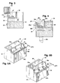
- FIG. 1 shows the preferred embodiment of the present invention in its environment of operation. It is shown that liquid 18, applied to a surface by applicator 10, is fed into receptacle area 19 via feed line 20. Liquid 18 travels below insert 16 and then exits through output aperture 27 in a gentle waterfall-like fashion. It may be appreciated by those skilled in the art that a variety of fasteners may be coated by the applicator of the present invention including by not limited to nuts, bolts, screws, male fasteners, female fasteners, inserts and the like. For purposes of this application, this detailed description will use fastener 24 as a typical example throughout. Fasteners 24 are passed over output aperture 27 in a rolling or rotating fashion so that they may be in contact with liquid 18a exiting output aperture 27.
- One full rotation of one of fasteners 24 is all that is necessary to apply liquid 18a 360 degrees around the circumference of the fastener of the precise width of output aperture 27.
- the width of output aperture 27 will create a corresponding patch of substantially the same width on fasteners 24 without any application on undesirable locations.
- Excess liquid 18b flows back within the cavity formed by insert 16 and exits the applicator through holes 17a which run completely through the applicator in a vertical direction. Excess liquid 18b exits the applicator 10 and empties into catch basin 22. Excess liquid 18b is then further removed from the applicator 10 by hose 23 which directs liquid 18b into a storage container or the like. Such excess liquid 18b may be recirculated through feed line 20 to be used again within the applicator.
- FIG. 2 an exploded view of the preferred embodiment shows the liquid applicator 10 of the present invention having a main nozzle body 12 with front plate 14 affixed to its front side 12a by screws 15 which protrude through apertures 15a. Screws 15 engage with receiving threads formed around the periphery of apertures 15b to secure front plate 14.
- the main nozzle body 12 and the front plate 14 together form the outer shell of the of the applicator 10.
- Insert 16 is positioned within this outer shell arrangement. Insert 16 is in contact with ledge 29 of the main nozzle body 12 created by trough 30. Insert 16 is secured to main nozzle body 12 by screws 17 through apertures 17a. Threads of screws 17 engage with receiving threads on the inside of apertures 17b to secure insert 16 onto ledge 29. Alternatively, holes 17b may not be threaded. In such an embodiment, screws 17 may pass directly through both sets of holes 17a and 17b and engage with receiving threads of a separate support means, such as a shelf.
- Apertures 17a are specifically designed to be oval in shape so that insert 16 may be moved forward and backward and then adjusted before tightening screws 17. Due to the adjustability of insert 16, output aperture 27, between front plate 14 and wall 16c of insert 16, may be controlled with accuracy. As a result of the adjustability of output aperture 27, the width of the liquid stream and the amount of liquid 18 flowing from output aperture 27 may be accurately and very precisely controlled.
- the floor of main nozzle body 12 is constructed as a stepped structure to form a trough 30 for flow direction of liquid 18.
- the liquid flows from receptacle 19 through trough 30 underneath insert 16 and then up through aperture 27 between front plate 14 and wall 16c of insert 16. This flow path of liquid 18 through the applicator may be clearly seen in FIG. 4.
- FIG. 4 the flow path of liquid 18 throughout the applicator is shown.
- Liquid 18 exits from aperture 27 in a waterfall-like fashion.
- fasteners 24 pass over applicator 10 in the region of aperture 27, they will come into contact with liquid 18a that is exposed just above the mouth of aperture 27.
- this excess liquid 18b either flows through apertures 17a or over front plate 14. In either case, this excess liquid 18b completely exits the entire applicator and may then enter catch trough 22.
- the flow path of liquid 18 through the applicator is essential to achieving its objective of gentle and precisely controlled application.
- the applicator 10 of the present invention does not use the assistance of any external pressure. It merely uses the force of gravity (ambient pressure) to assist the flow of liquid.
- the novel flow path of the present invention is employed.
- the liquid 18 first flows in a downward direction with the force of gravity. Liquid 18 then flows in a lateral direction in the area of trough 30. Finally, liquid 18 flows in an upward direction against the force of gravity. Since the top edge 19a of receptacle 19, which is always maintained completely full, is at a height greater than the top edge 14a of output aperture 27, a lack of equilibrium will occur. Due to the laws of physics relating to the pressure and volume in a system, the two levels of liquid within the same system will seek to become equal or in equilibrium. If the difference between two heights in a fluid system is great, then liquid will flow from the lower side at an increased rate to achieve equilibrium. Since the difference in the in the respective heights in the present invention is relatively small, a slow and gentle flow will result out of the end with the lower height, namely output aperture 27.
- the waterfall flow of the present invention is critical to achieving proper application of liquid with microencapsulated adhesive to a fastener such as a screw, insert or the like. Any other means, such as spraying, would be unacceptable for applying a proper, precise coating of liquid to the threads or other predetermined location on a fastener.
- FIGS. 5A and 5B Another advantageous feature of the present invention is shown in FIGS. 5A and 5B.
- a novel feature of applicator 10 of the present invention is the ability to accurately control the flow of liquid 18 out of output aperture 27 over top edge 14a. This is accomplished by the adjustability of insert 16 positioned on ledges 29. Since insert 16 is slidably adjustable along ledges 29 and can be secured anywhere along ledges 29 by screws 17, the aperture created between wall 16c of insert 16 and front plate 14 can be precisely varied.
- an applicator 10 is shown with insert 16 disposed within main nozzle body 12 and front plate 14. Insert 16 is secured down onto ledges 29 so that aperture 27x is quite small allowing for a narrow application of liquid 18 onto fasteners 24.
- the resultant application of liquid on the fasteners 24 will be a thin 360 degree coating of liquid around the threads of the fastener as shown in FIG. 1.
- insert 16 may be screwed down to ledges 29 so that aperture 27y, as in FIG 5B, is quite large and considerably wider than aperture 27x allowing for a wider application of liquid onto fasteners 24.
- the resultant application of liquid on the threads of the fastener with an adjustment as shown in FIG. 5B will be a wider 360 degree coating of liquid around the threads of the fastener.
- the width of liquid application is adjustable according to the desired application.
- the present applicator is employed as part of an entire system. As shown in FIG. 1, the applicator applies liquid to the portion of the fastener passing over output aperture 27. First, the applicator must be adjusted according to the desired application. If a wide liquid application covering several threads is required, aperture 27 will be adjusted to be wide. If a narrow patch is required covering only a single or half of a thread, a narrow aperture 27 will be used.
- liquid 18 may be fed into receptacle 19. Within a few seconds, liquid will begin to fall by gravity over edge 14a and through output aperture 27 into holes 17a. At this point, a conveyor system or the like may be activated to continuously pass fasteners over aperture 27. Once the liquid is applied in desired fashion, the fastener may then be moved away from the applicator to an area for curing the liquid on the fasteners, if required. The result is a precise application of liquid on a predetermined portion of the fastener.
- the present invention may be employed in a wide array of uses that specifically require gentle application of liquid. The invention may be used to apply non-adhesive liquid and may also be used to apply liquid to surfaces that are without threads.
Landscapes
- Engineering & Computer Science (AREA)
- General Engineering & Computer Science (AREA)
- Mechanical Engineering (AREA)
- Coating Apparatus (AREA)
Applications Claiming Priority (2)
| Application Number | Priority Date | Filing Date | Title |
|---|---|---|---|
| US737460 | 1991-07-29 | ||
| US07/737,460 US5236505A (en) | 1991-07-29 | 1991-07-29 | Apparatus and method for applying liquid material to a fastener |
Publications (1)
| Publication Number | Publication Date |
|---|---|
| EP0526005A1 true EP0526005A1 (fr) | 1993-02-03 |
Family
ID=24964018
Family Applications (1)
| Application Number | Title | Priority Date | Filing Date |
|---|---|---|---|
| EP92306144A Withdrawn EP0526005A1 (fr) | 1991-07-29 | 1992-07-03 | Appareil et méthode pour l'application d'un matériau liquide sur des attaches taraudées |
Country Status (2)
| Country | Link |
|---|---|
| US (1) | US5236505A (fr) |
| EP (1) | EP0526005A1 (fr) |
Cited By (2)
| Publication number | Priority date | Publication date | Assignee | Title |
|---|---|---|---|---|
| GB2409889A (en) * | 2004-01-07 | 2005-07-13 | Ford Global Tech Llc | A method for noise reduction between juxtaposed components |
| CN105396755A (zh) * | 2015-12-31 | 2016-03-16 | 京东方科技集团股份有限公司 | 一种涂胶机头、涂胶机及涂胶方法 |
Families Citing this family (4)
| Publication number | Priority date | Publication date | Assignee | Title |
|---|---|---|---|---|
| US5511510A (en) * | 1994-01-26 | 1996-04-30 | Duffy; Richard J. | Resin coated fastener and apparatus and method for manufacture of same |
| US5679160A (en) * | 1995-06-07 | 1997-10-21 | Nd Industries, Inc. | Apparatus for coating threaded fasteners |
| US6027568A (en) * | 1996-06-12 | 2000-02-22 | Nd Industries, Inc. | Apparatus for processing fasteners |
| US6554903B1 (en) | 2000-07-19 | 2003-04-29 | Nylok Corporation | Unitary spray nozzle |
Citations (5)
| Publication number | Priority date | Publication date | Assignee | Title |
|---|---|---|---|---|
| US3383054A (en) * | 1967-07-31 | 1968-05-14 | Crompton & Knowles Corp | Coating nozzle |
| US3502494A (en) * | 1965-11-04 | 1970-03-24 | Fuji Photo Film Co Ltd | Process and apparatus for continuous fluid coating of a traveling web |
| AT304958B (de) * | 1966-12-05 | 1973-02-12 | Usm Corp | Befestigungsmittel und Verfahren zu seiner Herstellung |
| US4465707A (en) * | 1980-07-08 | 1984-08-14 | Fuji Photo Film Co., Ltd. | Coating method |
| US4667879A (en) * | 1985-08-21 | 1987-05-26 | Nordson Corporation | Thermoplastic material applicator having an adjustable slot nozzle |
Family Cites Families (5)
| Publication number | Priority date | Publication date | Assignee | Title |
|---|---|---|---|---|
| US3004505A (en) * | 1957-09-30 | 1961-10-17 | Western Electric Co | Soldering device |
| US3216642A (en) * | 1962-03-22 | 1965-11-09 | Verter Walton G De | Wave-type solder fountain |
| US3341354A (en) * | 1964-03-11 | 1967-09-12 | Continental Oil Co | Curtain coating method and apparatus for applying a non-uniform liquid coating material to sheet stock |
| US3927409A (en) * | 1972-05-01 | 1975-12-16 | Varian Associates | Multistage thin film toning system for developing charged images |
| US3972631A (en) * | 1975-06-11 | 1976-08-03 | Armstrong Cork Company | Adhesive applicator |
-
1991
- 1991-07-29 US US07/737,460 patent/US5236505A/en not_active Expired - Lifetime
-
1992
- 1992-07-03 EP EP92306144A patent/EP0526005A1/fr not_active Withdrawn
Patent Citations (5)
| Publication number | Priority date | Publication date | Assignee | Title |
|---|---|---|---|---|
| US3502494A (en) * | 1965-11-04 | 1970-03-24 | Fuji Photo Film Co Ltd | Process and apparatus for continuous fluid coating of a traveling web |
| AT304958B (de) * | 1966-12-05 | 1973-02-12 | Usm Corp | Befestigungsmittel und Verfahren zu seiner Herstellung |
| US3383054A (en) * | 1967-07-31 | 1968-05-14 | Crompton & Knowles Corp | Coating nozzle |
| US4465707A (en) * | 1980-07-08 | 1984-08-14 | Fuji Photo Film Co., Ltd. | Coating method |
| US4667879A (en) * | 1985-08-21 | 1987-05-26 | Nordson Corporation | Thermoplastic material applicator having an adjustable slot nozzle |
Cited By (3)
| Publication number | Priority date | Publication date | Assignee | Title |
|---|---|---|---|---|
| GB2409889A (en) * | 2004-01-07 | 2005-07-13 | Ford Global Tech Llc | A method for noise reduction between juxtaposed components |
| CN105396755A (zh) * | 2015-12-31 | 2016-03-16 | 京东方科技集团股份有限公司 | 一种涂胶机头、涂胶机及涂胶方法 |
| CN105396755B (zh) * | 2015-12-31 | 2017-12-08 | 京东方科技集团股份有限公司 | 一种涂胶机头、涂胶机及涂胶方法 |
Also Published As
| Publication number | Publication date |
|---|---|
| US5236505A (en) | 1993-08-17 |
Similar Documents
| Publication | Publication Date | Title |
|---|---|---|
| US5964551A (en) | Vibratory/pneumatic powder coating apparatus and method | |
| EP0237746B1 (fr) | Appareil de distribution d'adhésif | |
| KR100310359B1 (ko) | 분말분무장치 | |
| US5236505A (en) | Apparatus and method for applying liquid material to a fastener | |
| US5253937A (en) | Method and apparatus for dispersing or dissolving particles of a pelletized material in a liquid | |
| US7975938B2 (en) | Coating system | |
| EP0133056A3 (en) | A rotary atomizer for coating workpieces with a fine layer of liquid material, and a method for operating the said atomizer | |
| US5599581A (en) | Method for pneumatically controlling discharge of particulate material | |
| US3717752A (en) | Particle spraying device | |
| EP0943961B1 (fr) | Appareil de couchage par rideau et procédé au réglage continu de la largeur | |
| US3625404A (en) | Apparatus and method for dispensing particulate material | |
| JPS62129177A (ja) | 液状粘着剤塗布装置 | |
| KR20170113726A (ko) | 점성 용액 스프레이 도포 장치 | |
| KR19980070780A (ko) | 폴리우레탄 슬라브재 발포체의 연속 생산 방법 및 장치 | |
| EP0131347A2 (fr) | Appareil permettant d'apporter uniformément un liquide de traitement ou une mousse | |
| US20050220931A1 (en) | Nozzle assembly for applying a liquid to a substrate | |
| CA1318181C (fr) | Buse de mouillage pour presses d'imprimerie | |
| JP2004531380A (ja) | 装置に対し相対的に移動する基材上に液体を分配する装置および方法 | |
| JP3618461B2 (ja) | 塗装装置 | |
| US4332211A (en) | Granule producing apparatus | |
| JP2908145B2 (ja) | ディスペンス装置 | |
| AU9432298A (en) | Atomizer foil, atomizer having such an atomizer foil and use of such atomizer foil | |
| JP7245047B2 (ja) | カーテンコータ | |
| JP2926505B2 (ja) | フローコーティング用ノズル | |
| SU1124071A1 (ru) | Устройство дл поверхностной обработки бумажного полотна на бумагоделательной машине |
Legal Events
| Date | Code | Title | Description |
|---|---|---|---|
| PUAI | Public reference made under article 153(3) epc to a published international application that has entered the european phase |
Free format text: ORIGINAL CODE: 0009012 |
|
| AK | Designated contracting states |
Kind code of ref document: A1 Designated state(s): DE ES FR GB IT |
|
| 17P | Request for examination filed |
Effective date: 19930113 |
|
| STAA | Information on the status of an ep patent application or granted ep patent |
Free format text: STATUS: THE APPLICATION HAS BEEN WITHDRAWN |
|
| 17Q | First examination report despatched |
Effective date: 19940615 |
|
| 18W | Application withdrawn |
Withdrawal date: 19940618 |