EP0526112B1 - Verfahren zum Nachweis von DNS-Basen mit Verwendung von Fluoreszenz - Google Patents
Verfahren zum Nachweis von DNS-Basen mit Verwendung von Fluoreszenz Download PDFInfo
- Publication number
- EP0526112B1 EP0526112B1 EP92306757A EP92306757A EP0526112B1 EP 0526112 B1 EP0526112 B1 EP 0526112B1 EP 92306757 A EP92306757 A EP 92306757A EP 92306757 A EP92306757 A EP 92306757A EP 0526112 B1 EP0526112 B1 EP 0526112B1
- Authority
- EP
- European Patent Office
- Prior art keywords
- fine particles
- hole
- moved
- fluorescence
- light
- Prior art date
- Legal status (The legal status is an assumption and is not a legal conclusion. Google has not performed a legal analysis and makes no representation as to the accuracy of the status listed.)
- Expired - Lifetime
Links
- 238000001917 fluorescence detection Methods 0.000 title description 6
- 239000010419 fine particle Substances 0.000 claims description 56
- 238000007664 blowing Methods 0.000 claims description 18
- 230000001678 irradiating effect Effects 0.000 claims description 6
- 230000003287 optical effect Effects 0.000 claims description 5
- 239000012634 fragment Substances 0.000 claims description 3
- 108020004414 DNA Proteins 0.000 description 6
- 238000001514 detection method Methods 0.000 description 6
- 108090000623 proteins and genes Proteins 0.000 description 5
- 230000002068 genetic effect Effects 0.000 description 4
- 241001465754 Metazoa Species 0.000 description 2
- NBIIXXVUZAFLBC-UHFFFAOYSA-N Phosphoric acid Chemical compound OP(O)(O)=O NBIIXXVUZAFLBC-UHFFFAOYSA-N 0.000 description 2
- OPTASPLRGRRNAP-UHFFFAOYSA-N cytosine Chemical compound NC=1C=CNC(=O)N=1 OPTASPLRGRRNAP-UHFFFAOYSA-N 0.000 description 2
- UYTPUPDQBNUYGX-UHFFFAOYSA-N guanine Chemical compound O=C1NC(N)=NC2=C1N=CN2 UYTPUPDQBNUYGX-UHFFFAOYSA-N 0.000 description 2
- 239000007788 liquid Substances 0.000 description 2
- 239000002773 nucleotide Substances 0.000 description 2
- 125000003729 nucleotide group Chemical group 0.000 description 2
- 230000002035 prolonged effect Effects 0.000 description 2
- 229930024421 Adenine Natural products 0.000 description 1
- GFFGJBXGBJISGV-UHFFFAOYSA-N Adenine Chemical compound NC1=NC=NC2=C1N=CN2 GFFGJBXGBJISGV-UHFFFAOYSA-N 0.000 description 1
- 102000053602 DNA Human genes 0.000 description 1
- 229960000643 adenine Drugs 0.000 description 1
- 229910000147 aluminium phosphate Inorganic materials 0.000 description 1
- 229940104302 cytosine Drugs 0.000 description 1
- 238000010586 diagram Methods 0.000 description 1
- 238000011835 investigation Methods 0.000 description 1
- 239000012528 membrane Substances 0.000 description 1
- 244000005700 microbiome Species 0.000 description 1
- 238000012986 modification Methods 0.000 description 1
- 230000004048 modification Effects 0.000 description 1
- 108020004707 nucleic acids Proteins 0.000 description 1
- 102000039446 nucleic acids Human genes 0.000 description 1
- 150000007523 nucleic acids Chemical class 0.000 description 1
- 239000013307 optical fiber Substances 0.000 description 1
- 239000004065 semiconductor Substances 0.000 description 1
- 230000035945 sensitivity Effects 0.000 description 1
- 239000000126 substance Substances 0.000 description 1
Images



Classifications
-
- G—PHYSICS
- G01—MEASURING; TESTING
- G01N—INVESTIGATING OR ANALYSING MATERIALS BY DETERMINING THEIR CHEMICAL OR PHYSICAL PROPERTIES
- G01N21/00—Investigating or analysing materials by the use of optical means, i.e. using sub-millimetre waves, infrared, visible or ultraviolet light
- G01N21/62—Systems in which the material investigated is excited whereby it emits light or causes a change in wavelength of the incident light
- G01N21/63—Systems in which the material investigated is excited whereby it emits light or causes a change in wavelength of the incident light optically excited
- G01N21/64—Fluorescence; Phosphorescence
- G01N21/6486—Measuring fluorescence of biological material, e.g. DNA, RNA, cells
-
- G—PHYSICS
- G01—MEASURING; TESTING
- G01N—INVESTIGATING OR ANALYSING MATERIALS BY DETERMINING THEIR CHEMICAL OR PHYSICAL PROPERTIES
- G01N15/00—Investigating characteristics of particles; Investigating permeability, pore-volume or surface-area of porous materials
- G01N15/10—Investigating individual particles
- G01N15/14—Optical investigation techniques, e.g. flow cytometry
- G01N15/1456—Optical investigation techniques, e.g. flow cytometry without spatial resolution of the texture or inner structure of the particle, e.g. processing of pulse signals
- G01N15/1459—Optical investigation techniques, e.g. flow cytometry without spatial resolution of the texture or inner structure of the particle, e.g. processing of pulse signals the analysis being performed on a sample stream
-
- H—ELECTRICITY
- H01—ELECTRIC ELEMENTS
- H01J—ELECTRIC DISCHARGE TUBES OR DISCHARGE LAMPS
- H01J43/00—Secondary-emission tubes; Electron-multiplier tubes
- H01J43/04—Electron multipliers
Definitions
- the present invention relates to a fluorescence detection of a fine particle, and more particularly to a fluorescence detection of a base (nucleotide) forming a gene.
- Deoxyribonucleic acid abbreviated to DNA is composed of bases as a primary component, sugar and phosphoric acid, and is in a double helix structure containing genetic information therein.
- the genetic information is present in each of the DNA fragments in the form of a sequence of bases.
- a strand of genes is found in the cell of an organism. For lower animals such as a microorganism, there are several thousands base pairs while for a higher animal having much more genetic information, there are several hundred millions to two billions and nine hundred millions of base pairs.
- the genetic information of DNA is determined by a sequence of adenine (A), guanine (G), cytosine (C), and thumine (T) which are bases (nucleotides) forming a nucleic acid. Investigation of the sequence of these bases is therefore the key to develop gene engineering and medical science.
- A adenine
- G guanine
- C cytosine
- T thumine
- each of the aforesaid bases produces specific fluorescence, and it has been practiced to identify the base depending upon the fluorescence produced.
- Production of fluorescence results from irradiation of exciting light onto the base.
- Detection of the fluorescence thus produced may preferably be performed using a high sensitivity detector such as photomultiplier tube.
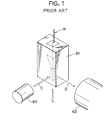
- a publication entitled "Chemical Physics Letters” (1990) 174, pages 552-557 discloses an arrangement for detecting fluorescence as shown in Fig. 1.
- An exciting light from a light source 62 is irradiated into a flow cell 61 wherein the direction C in which the exciting light is irradiated is perpendicular to the direction A 1 in which fine particles are supplied to the flow cell 61.
- the fluorescence emitting in the direction of D is detected by a photomultiplier tuber 63, wherein the direction D is perpendicular to both the direction A 1 and the excited light irradiation direction C.
- the arrangement as above is, however, incapable of accurately and efficiently detect the fluorescence from the fine particle such as the base of gene. Because a single DNA fragment has an extremely large number of bases, thus each base is extremely small in size, and the fluorescence produced from each base is extremely minute. It is therefore difficult to identify the kind of the base with the detection of the fluorescence which is taken place for an ultra short period of time when the exciting light beam passes through the fine particle.
- a device for detecting fluorescence produced from a fine particle comprises:
- the direction in which the fine particles are moved by the blowing means may either be substantially orthogonal or substantially parallel to the direction in which the fine particles are supplied by the supplying means.
- the fine particle supplied from the supplying means is introduced into the through-hole of the detecting means by the blowing means, and the fine particle is kept irradiated while it stays in the through-hole. Therefore, the fluorescence producing time is prolonged and the fluorescence thus produced can be captured by the light detecting surface provided in the inner circumference of the through-hole.
- Fine particle fluorescence detection device according to a preferred embodiment of the present invention is shown in Fig. 2.
- the device includes a single molecular, continuously trapable flow cell 10, a flow booster 20 which produces gas jet for blowing fine particles, a light guide member 30 arranged to emit an exciting light coaxially of the flow booster 20, and a hollow photomultiplier 40 which has an axially extending through-hole 41 and is arranged so that the through-hole 41 is in coaxial relation to the flow booster 20.
- the hollow photomultiplier 40 serves as a photodetector.
- the fine particle dropping direction A 1 from the flow cell 10 is orthogonal to both the gas jetting direction B from the flow booster 20 and the direction C of an optical axis of the exciting light.
- a light source (not shown) is connected to the light guide member 30.
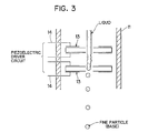
- the flow cell 10 has two supersonic traps 12 sandwitched between three-divided flow cell blocks 11. As shown in Fig. 3, each supersonic trap 12 has a piezoelectric element 13 which is connected to a piezoelectric driver circuit through wires 14.
- the flow cell 10 has a flow path through which fine particles dispersed liquid is allowed to flow.
- the piezoelectric elements 13 form a standing wave in the interior of the flow path, whereby the liquid droplets are produced and are fell down.
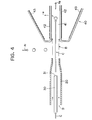
- Fig. 4 illustrates a state in which the fine particle droplets are dropped from the flow cell 10.
- the flow booster 20, the light guide member 30 and the hollow photomultiplier 40 are arranged in axial alignment with one another in a direction orthogonal to the fine particle dropping direction A 1 .
- the light guide member 30 is coaxially disposed interiorly of the flow booster 20.
- a photocathode 42 is provided over the entire inner circumference of the through-hole of the hollow multiplier 40.
- a first dynode 43 is provided in substantially confrontation with the photocathode 42.
- the dropped fine particle droplets are directed toward the inner space of the through-hole 41 of the hollow multiplier 40 due to gas jet produced from the flow booster 20.
- the fine particle is moved at a higher speed than the dropping speed in the direction of A 2 same as the gas ejection direction B. At this time, the fine particle is kept irradiated by the exciting light emitted from the end surface 31 of the light guide member 30, thus produce fluorescence. Since the production of the fluorescence occurs in the internal space of the photomultiplier 40, the major part of the fluorescence are incident on the photocathode 42 to thus produce photoelectrons. Therefore, the fluorescence detection can be performed with high efficiency.
- Fig. 5 shows an internal arrangement of the hollow photomultiplier 40.
- the photocathode 42 is provided on the entire inner circumference of a smaller-diameter portion of the through-hole 41.
- the first dynode 43 is provided in substantially confrontation with the photocathode 42 and the second dynode is provided to receive the secondary electrons emitted from the first dynode 43.
- appropriate number of stages of the dynodes are arranged in succession in the axial direction of the photomultiplier 40.
- An anode 45 is provided to receive the electrons emitted from the final stage dynode.
- the output of the anode 45 is amplified by an amplifier 46 and derived from an output terminal (OUT). In this manner, the photoelectrons produced depending on the fluorescence of the fine particle are successively multiplied by a number of dynodes 43, 44 and are taken out from the output terminal (OUT).
- the direction A 2 in which the fine particle advances is in coincidence with the optical axial direction C of the exciting light, so that the fine particles can be excited by the converged exciting light beam over a long period of time. Further, detection of the fluorescence can be attained with high efficiency, since the fluorescence emanating from the fine particles is produced in the interior of the through-hole 41 of the hollow photomultiplier 40 and thus the fluorescence is almost perfectly incident on the photocathode 42. As such, extremely minute fluorescence emanating from a fine particle such as a base forming a gene can be detected.
- the fine particle supplying direction and the optical axis of the exciting light are set substantially in parallel to each other. More specifically, a single molecular, continuous trappable flow cell 10 and an optical fiber or light guide member 30 are disposed interiorly of a cylindrical member 70 to be in parallel to each other. To introduce the fine particles supplied from the flow cell 10 into a photo-detecting cylinder 50 at a higher speed, air is blown into the inner space of the cylindrical member 70. Two sets of photodetectors 40a 1 , through 40a 2 , and 40b 1 through 40b 2 , are provided on the outer circumference of the photo-detecting cylinder 50. The photodetectors 40a 1 through 40a 2 , or 40b 1 , through 40b 2 , are arranged equi-angularly. It is preferable that the number of the photodetectors in each set be 6 or 8.
- bubble jet nozzles used in bubble jet printers may be used in place of the ultrasonic traps for use in a single molecular, continuously trappable flow cell.
- Two or three hollow photomultipliers 40 may be coupled together in series to provide two- or three-stage hollow multiplier with which the detection efficiency can be further improved. Provision of a wavelength filter in the opening of the through-hole 41 can prevent detection of noises caused by scattering of the exciting light.
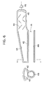
- a photomultiplier of the type shown in Fig. 6 can be employed.
- the photomultiplier shown therein has a photocathode 42 on an inner arcuate surface of the photomultipler.
- a light reflective membrane 48 is provided partially in the inner circumference of the through-hole 41 in confronting relation to the photocathode 42.
- the photomultipler shown in Fig. 6 is advantageous in the simplicity of the internal arrangement. Semiconductor devices can also be employed as the photodetector.
- the fine particle advancing in the interior of the photomultiplier is kept irradiated by the exciting light. Therefore, a period of time during which the florescence is produced can be prolonged. Further, with the use of the hollow multiplier having a detecting surface formed in the entire inner circumference of a through-hole, fluorescence in any of the directions can be captured. Accordingly, fluorescence produced from successively supplied fine particles such as DNA bases can be detected with high accuracy and excellent efficiency.
Landscapes
- Health & Medical Sciences (AREA)
- Chemical & Material Sciences (AREA)
- Life Sciences & Earth Sciences (AREA)
- General Physics & Mathematics (AREA)
- Pathology (AREA)
- Analytical Chemistry (AREA)
- Biochemistry (AREA)
- General Health & Medical Sciences (AREA)
- Physics & Mathematics (AREA)
- Immunology (AREA)
- Dispersion Chemistry (AREA)
- Engineering & Computer Science (AREA)
- Biomedical Technology (AREA)
- Molecular Biology (AREA)
- Nuclear Medicine, Radiotherapy & Molecular Imaging (AREA)
- Investigating, Analyzing Materials By Fluorescence Or Luminescence (AREA)
- Investigating Or Analysing Biological Materials (AREA)
- Photometry And Measurement Of Optical Pulse Characteristics (AREA)
- Measuring Or Testing Involving Enzymes Or Micro-Organisms (AREA)
Claims (9)
- Eine Vorrichtung zum Nachweis von Fluoreszenz, die von einem feinen Partikel produziert ist, miteinem Zuführmittel (10) zum Zuführen feiner Partikel in einer Richtung,einem Strahlungsmittel (30) zum Strahlen eines anregenden Lichtstrahls auf die feinen Partikel undeinem Nachweismittel (40) zum Nachweis von Fluoreszenz, die von den feinen Partikeln produziert ist,gekennzeichnet durch ein Blasmittel (20) zum Blasen der feinen Partikel, um sie sich in einer Richtung mit einer höheren Geschwindigkeit bewegen zu lassen als der, mit der die feinen Partikel vom Zuführmittel zugeführt werden, wobei das Strahlungsmittel eine optische Achse in Ausrichtung mit der Richtung hat, in der die feinen Partikel vom Blasmittel bewegt werden, und wobei das Nachweismittel (40) mit einer Durchbohrung (41) versehen ist, durch die das anregende Licht und die vom Blasmittel bewegten feinen Partikel passieren, wodurch das Nachweismittel Fluoreszenz nachweist, die von dem anregenden Licht angeregt ist, wenn die feinen Partikel vom Blasmittel bewegt werden.
- Die Vorrichtung nach Anspruch 1, wobei die Richtung, in der die feinen Partikel vom Blasmittel (20) bewegt werden, im wesentlichen rechtwinklig zur Richtung ist, in der die feinen Partikel vom Zuführmittel (10) zugeführt werden.
- Die Vorrichtung nach Anspruch 1, wobei die Richtung, in der die feinen Partikel vom Blasmittel (20) bewegt werden, im wesentlichen parallel zur Richtung ist, in der die feinen Partikel vom Zuführmittel (10) zugeführt werden.
- Die Vorrichtung nach Anspruch 1, 2 oder 3, wobei das Nachweismittel (40) einen hohlen Fotomultiplier, in dem eine Durchbohrung (41) durch einen inneren Umfang begrenzt ist, eine auf dem inneren Umfang der Durchbohrung gebildete Fotokathode, eine Anzahl von Dynoden (43, 44) sowie eine Anode (45) aufweist, wobei der Fotomultiplier in einer Orientierung angeordnet ist, so daß die vom Blasmittel bewegten feinen Partikel durch die Durchbohrung (41) passieren.
- Die Vorrichtung nach Anspruch 1, 2 oder 3, wobei das Nachweismittel (40) einen Fotomultipier, bei dem die Durchbohrung (41) von einem inneren Umfang begrenzt ist, ein auf einem Teil des inneren Umfangs der Durchbohrung gebildetes reflektierendes Teil (48) zum Reflektieren von Licht, eine zum Aufnehmen des vom reflektierenden Teil reflektierten Lichts angeordnete Fotokathode (42), eine Anzahl von Dynoden (43, 44) sowie eine Anode (45) aufweist, wobei der Fotomultiplier in einer Orientierung angeordnet ist, so daß die vom Blasmittel bewegten feinen Partikel durch die Durchbohrung passieren.
- Die Vorrichtung nach Anspruch 1, 2 oder 3, wobei das Nachweismittel einen lichtaufnehmenden Zylinder (50), durch den die vom Blasmittel bewegten feinen Partikel passieren, sowie eine Anzahl von Lichtdetektoren (40a, 40b) aufweist, die auf dem Umfang des lichtaufnehmenden Zylinders angeordnet sind.
- Die Vorrichtung nach Anspruch 6, wobei sechs Lichtdetektoren (40a1 bis 40a6, 40b1 bis 40b6) in gleichem Winkel zueinander auf dem Umfang des lichtaufnehmenden Zylinders angeordnet sind.
- Die Vorrichtung nach Anspruch 6, wobei acht Lichtdetektoren (40a1 bis 40a8, 40b1 bis 40b8) in gleichem Winkel zueinander auf dem Umfang des lichtaufnehmenen Zylinders angeordnet sind.
- Die Vorrichtung nach Anspruch 1, wobei das Zuführmittel (10) DNS-Fragmente während des Separierens in Basen zuführt.
Applications Claiming Priority (2)
| Application Number | Priority Date | Filing Date | Title |
|---|---|---|---|
| JP3182478A JPH0526810A (ja) | 1991-07-23 | 1991-07-23 | 微粒子の螢光検出装置 |
| JP182478/91 | 1991-07-23 |
Publications (3)
| Publication Number | Publication Date |
|---|---|
| EP0526112A2 EP0526112A2 (de) | 1993-02-03 |
| EP0526112A3 EP0526112A3 (en) | 1993-11-10 |
| EP0526112B1 true EP0526112B1 (de) | 1997-10-15 |
Family
ID=16118978
Family Applications (1)
| Application Number | Title | Priority Date | Filing Date |
|---|---|---|---|
| EP92306757A Expired - Lifetime EP0526112B1 (de) | 1991-07-23 | 1992-07-23 | Verfahren zum Nachweis von DNS-Basen mit Verwendung von Fluoreszenz |
Country Status (4)
| Country | Link |
|---|---|
| US (1) | US5260029A (de) |
| EP (1) | EP0526112B1 (de) |
| JP (1) | JPH0526810A (de) |
| DE (1) | DE69222710T2 (de) |
Families Citing this family (15)
| Publication number | Priority date | Publication date | Assignee | Title |
|---|---|---|---|---|
| JP3290786B2 (ja) * | 1993-11-26 | 2002-06-10 | シスメックス株式会社 | 粒子分析装置 |
| US5690894A (en) * | 1995-05-23 | 1997-11-25 | The Regents Of The University Of California | High density array fabrication and readout method for a fiber optic biosensor |
| US5837196A (en) * | 1996-01-26 | 1998-11-17 | The Regents Of The University Of California | High density array fabrication and readout method for a fiber optic biosensor |
| AT403745B (de) * | 1996-02-29 | 1998-05-25 | Avl Verbrennungskraft Messtech | Messanordnung mit einem für anregungs- und messstrahlung transparentem trägerelement |
| US5714388A (en) * | 1996-08-14 | 1998-02-03 | Bayer Corporation | Apparatus and method for detecting chemiluminescent light |
| DE19702557C2 (de) * | 1997-01-24 | 1999-06-17 | Fraunhofer Ges Forschung | Vorrichtung zur Erfassung von diffus emittiertem Licht |
| US6139800A (en) * | 1997-06-23 | 2000-10-31 | Luminex Corporation | Interlaced lasers for multiple fluorescence measurement |
| JP4215397B2 (ja) | 1998-05-14 | 2009-01-28 | ルミネックス コーポレイション | 多重分析物診断システム |
| US6830729B1 (en) | 1998-05-18 | 2004-12-14 | University Of Washington | Sample analysis instrument |
| CA2320296A1 (en) * | 1998-05-18 | 1999-11-25 | University Of Washington | Liquid analysis cartridge |
| US6355921B1 (en) | 1999-05-17 | 2002-03-12 | Agilent Technologies, Inc. | Large dynamic range light detection |
| US7167615B1 (en) | 1999-11-05 | 2007-01-23 | Board Of Regents, The University Of Texas System | Resonant waveguide-grating filters and sensors and methods for making and using same |
| IL162761A (en) * | 2004-06-28 | 2013-04-30 | Avraham Shekalim | A device for continuous glucose measurement in body fluids |
| US9500588B2 (en) | 2014-09-30 | 2016-11-22 | Perkinelmer Health Sciences, Inc. | Flow cell modules and liquid sample analyzers and methods including same |
| US9581491B2 (en) | 2014-09-30 | 2017-02-28 | Perkinelmer Health Sciences, Inc. | Flow cell modules and liquid sample analyzers and methods including same |
Family Cites Families (12)
| Publication number | Priority date | Publication date | Assignee | Title |
|---|---|---|---|---|
| US3849654A (en) * | 1973-10-19 | 1974-11-19 | H Malvin | Fluorescence cuvette |
| US4173415A (en) * | 1976-08-20 | 1979-11-06 | Science Spectrum, Inc. | Apparatus and process for rapidly characterizing and differentiating large organic cells |
| US4115699A (en) * | 1977-06-16 | 1978-09-19 | Kabushiki Kaisha Nihon Kotai Kenkyujo | Apparatus for sensitive detection and quantitative analysis of biological and biochemical substances |
| GB1598779A (en) * | 1978-05-25 | 1981-09-23 | Itt Creed | Ink-jet printers |
| DE2943116C2 (de) * | 1979-10-25 | 1986-06-19 | Gesellschaft für Strahlen- und Umweltforschung mbH, 8000 München | Einrichtung zur durchflußcytometrischen Reaktions- und/oder Diffusionsmessung |
| JPS59174742A (ja) * | 1983-03-25 | 1984-10-03 | Agency Of Ind Science & Technol | 微小粒子を区分又は選別する方法及びその装置 |
| US4600302A (en) * | 1984-03-26 | 1986-07-15 | Becton, Dickinson And Company | Flow cytometry apparatus with uniform incoherent light excitation |
| US4643566A (en) * | 1984-07-20 | 1987-02-17 | Canon Kabushiki Kaisha | Particle analyzing apparatus |
| JPH07118294B2 (ja) * | 1987-02-13 | 1995-12-18 | 浜松ホトニクス株式会社 | 光電子増倍管 |
| US4855930A (en) * | 1987-03-27 | 1989-08-08 | Chimerix Corporation | Method and appartatus for improved time-resolved fluorescence spectroscopy |
| US4867559A (en) * | 1988-01-06 | 1989-09-19 | Amoco Corporation | Liquid/liquid fiber-optic fluorescence detector and absorbance analyzer |
| DE69025256T2 (de) * | 1989-10-11 | 1996-06-27 | Canon Kk | Gerät und Verfahren zur Trennung von Teilchen aus flüssigkeitssuspendierten Teilchen in Zusammenhang mit deren Eigenschaften |
-
1991
- 1991-07-23 JP JP3182478A patent/JPH0526810A/ja active Pending
-
1992
- 1992-07-23 US US07/917,384 patent/US5260029A/en not_active Expired - Fee Related
- 1992-07-23 EP EP92306757A patent/EP0526112B1/de not_active Expired - Lifetime
- 1992-07-23 DE DE69222710T patent/DE69222710T2/de not_active Expired - Fee Related
Also Published As
| Publication number | Publication date |
|---|---|
| DE69222710T2 (de) | 1998-02-12 |
| EP0526112A3 (en) | 1993-11-10 |
| JPH0526810A (ja) | 1993-02-02 |
| EP0526112A2 (de) | 1993-02-03 |
| DE69222710D1 (de) | 1997-11-20 |
| US5260029A (en) | 1993-11-09 |
Similar Documents
| Publication | Publication Date | Title |
|---|---|---|
| EP0526112B1 (de) | Verfahren zum Nachweis von DNS-Basen mit Verwendung von Fluoreszenz | |
| US5990484A (en) | Method and apparatus for measuring fluorescence | |
| US20200333237A1 (en) | Compact multi-color flow cytometer | |
| US7706419B2 (en) | Optical systems for microarray scanning | |
| JP3641619B2 (ja) | 生体試料検査装置 | |
| US6448064B1 (en) | Integrated circuit biochip microsystem | |
| JPH0817389A (ja) | 電子管 | |
| EP0793856A1 (de) | Ringförmiger mehrteiligfotovervielfacher mit zylindrischer fotokathode | |
| US10514337B2 (en) | Device for time controlled fluorescence detection | |
| JPH028775A (ja) | イオン化放射線用高解像力自動蛍光透視鏡 | |
| JPH07118294B2 (ja) | 光電子増倍管 | |
| US5410211A (en) | Electron tube with an electron multiplier having a plurality of stages of dynodes | |
| TWI722158B (zh) | 光倍增管偵測器總成及相關檢測系統 | |
| US5180943A (en) | Photomultiplier tube with dynode array having venetian-blind structure | |
| US5453609A (en) | Non cross talk multi-channel photomultiplier using guided electron multipliers | |
| US20070202533A1 (en) | High speed DNA sequencer and method | |
| JP2000304697A (ja) | 蛍光寿命測定方法および装置 | |
| JP3270707B2 (ja) | イオン検出装置 | |
| JP2662346B2 (ja) | 光電子増倍管 | |
| JP2004294106A (ja) | 入射光の二次元位置検出装置 | |
| JPH07326315A (ja) | 正負イオン検出装置 | |
| JP2551449B2 (ja) | 放射線画像情報読取装置 | |
| US20050258356A1 (en) | Bipolar ion detector | |
| CN221858374U (zh) | Pcr光源模组、荧光接收模组及生物样本检测设备 | |
| JP4274956B2 (ja) | 微弱光検出方法および装置 |
Legal Events
| Date | Code | Title | Description |
|---|---|---|---|
| PUAI | Public reference made under article 153(3) epc to a published international application that has entered the european phase |
Free format text: ORIGINAL CODE: 0009012 |
|
| AK | Designated contracting states |
Kind code of ref document: A2 Designated state(s): DE FR GB |
|
| PUAL | Search report despatched |
Free format text: ORIGINAL CODE: 0009013 |
|
| AK | Designated contracting states |
Kind code of ref document: A3 Designated state(s): DE FR GB |
|
| 17P | Request for examination filed |
Effective date: 19940504 |
|
| 17Q | First examination report despatched |
Effective date: 19960612 |
|
| GRAG | Despatch of communication of intention to grant |
Free format text: ORIGINAL CODE: EPIDOS AGRA |
|
| GRAH | Despatch of communication of intention to grant a patent |
Free format text: ORIGINAL CODE: EPIDOS IGRA |
|
| GRAH | Despatch of communication of intention to grant a patent |
Free format text: ORIGINAL CODE: EPIDOS IGRA |
|
| GRAA | (expected) grant |
Free format text: ORIGINAL CODE: 0009210 |
|
| AK | Designated contracting states |
Kind code of ref document: B1 Designated state(s): DE FR GB |
|
| REF | Corresponds to: |
Ref document number: 69222710 Country of ref document: DE Date of ref document: 19971120 |
|
| ET | Fr: translation filed | ||
| PLBE | No opposition filed within time limit |
Free format text: ORIGINAL CODE: 0009261 |
|
| STAA | Information on the status of an ep patent application or granted ep patent |
Free format text: STATUS: NO OPPOSITION FILED WITHIN TIME LIMIT |
|
| 26N | No opposition filed | ||
| PGFP | Annual fee paid to national office [announced via postgrant information from national office to epo] |
Ref country code: FR Payment date: 20010712 Year of fee payment: 10 |
|
| PGFP | Annual fee paid to national office [announced via postgrant information from national office to epo] |
Ref country code: DE Payment date: 20010716 Year of fee payment: 10 |
|
| PGFP | Annual fee paid to national office [announced via postgrant information from national office to epo] |
Ref country code: GB Payment date: 20010718 Year of fee payment: 10 |
|
| REG | Reference to a national code |
Ref country code: GB Ref legal event code: IF02 |
|
| PG25 | Lapsed in a contracting state [announced via postgrant information from national office to epo] |
Ref country code: GB Free format text: LAPSE BECAUSE OF NON-PAYMENT OF DUE FEES Effective date: 20020723 |
|
| PG25 | Lapsed in a contracting state [announced via postgrant information from national office to epo] |
Ref country code: DE Free format text: LAPSE BECAUSE OF NON-PAYMENT OF DUE FEES Effective date: 20030201 |
|
| GBPC | Gb: european patent ceased through non-payment of renewal fee |
Effective date: 20020723 |
|
| PG25 | Lapsed in a contracting state [announced via postgrant information from national office to epo] |
Ref country code: FR Free format text: LAPSE BECAUSE OF NON-PAYMENT OF DUE FEES Effective date: 20030331 |
|
| REG | Reference to a national code |
Ref country code: FR Ref legal event code: ST |