EP0526482B1 - Commande adaptative du freinage - Google Patents
Commande adaptative du freinage Download PDFInfo
- Publication number
- EP0526482B1 EP0526482B1 EP91907529A EP91907529A EP0526482B1 EP 0526482 B1 EP0526482 B1 EP 0526482B1 EP 91907529 A EP91907529 A EP 91907529A EP 91907529 A EP91907529 A EP 91907529A EP 0526482 B1 EP0526482 B1 EP 0526482B1
- Authority
- EP
- European Patent Office
- Prior art keywords
- pressure
- value
- volume
- brake
- main air
- Prior art date
- Legal status (The legal status is an assumption and is not a legal conclusion. Google has not performed a legal analysis and makes no representation as to the accuracy of the status listed.)
- Expired - Lifetime
Links
Images



Classifications
-
- B—PERFORMING OPERATIONS; TRANSPORTING
- B60—VEHICLES IN GENERAL
- B60T—VEHICLE BRAKE CONTROL SYSTEMS OR PARTS THEREOF; BRAKE CONTROL SYSTEMS OR PARTS THEREOF, IN GENERAL; ARRANGEMENT OF BRAKING ELEMENTS ON VEHICLES IN GENERAL; PORTABLE DEVICES FOR PREVENTING UNWANTED MOVEMENT OF VEHICLES; VEHICLE MODIFICATIONS TO FACILITATE COOLING OF BRAKES
- B60T13/00—Transmitting braking action from initiating means to ultimate brake actuator with power assistance or drive; Brake systems incorporating such transmitting means, e.g. air-pressure brake systems
- B60T13/10—Transmitting braking action from initiating means to ultimate brake actuator with power assistance or drive; Brake systems incorporating such transmitting means, e.g. air-pressure brake systems with fluid assistance, drive, or release
- B60T13/66—Electrical control in fluid-pressure brake systems
- B60T13/665—Electrical control in fluid-pressure brake systems the systems being specially adapted for transferring two or more command signals, e.g. railway systems
-
- B—PERFORMING OPERATIONS; TRANSPORTING
- B60—VEHICLES IN GENERAL
- B60T—VEHICLE BRAKE CONTROL SYSTEMS OR PARTS THEREOF; BRAKE CONTROL SYSTEMS OR PARTS THEREOF, IN GENERAL; ARRANGEMENT OF BRAKING ELEMENTS ON VEHICLES IN GENERAL; PORTABLE DEVICES FOR PREVENTING UNWANTED MOVEMENT OF VEHICLES; VEHICLE MODIFICATIONS TO FACILITATE COOLING OF BRAKES
- B60T17/00—Component parts, details, or accessories of power brake systems not covered by groups B60T8/00, B60T13/00 or B60T15/00, or presenting other characteristic features
- B60T17/18—Safety devices; Monitoring
- B60T17/22—Devices for monitoring or checking brake systems; Signal devices
- B60T17/228—Devices for monitoring or checking brake systems; Signal devices for railway vehicles
Definitions
- the invention relates to an adaptive brake control for indirectly acting air brakes with an electro-pneumatic driver's brake valve according to the preamble of claim 1.
- the US-PS 4,859,000 shows an adaptive brake control with an electro-pneumatic driver brake valve and a relay valve.
- HL main air line
- three sensors are arranged, which measure the flow rate, the absolute pressure and the temperature of the air.
- Additional pressure sensors on the driver's brake valve measure the pressure of a control pressure container for the relay valve (A pressure) and the pressure in the driver's brake valve for the brake pressure request.
- the output signals of all these sensors are fed to a microprocessor and evaluated. Primarily, the volume of the air flowing out of the HL via the relay valve to the atmosphere when braking or flowing into the HL via the relay valve when the brakes are released is measured.
- the volume of the air fed in is measured from a fully ventilated HL until the train is completely released and the value is saved. In the event of a complete venting later, a comparison is then made as to whether the same volume has flowed out. Conversely, this comparison value can later be used to determine whether the brakes are completely released.
- the volume flowing out of the HL when braking is always compared with the volume flowing into the HL when releasing, from which changes in the train configuration (e.g. accidentally closing a shut-off valve on a car) or other malfunctions can be detected.
- the value of the pressure in the A container is stored in this publication at the point in time at which the flow rate of the replenished air into the HL approaches zero. At this point, the pressures in the A tank and the HL are approximately the same. For the braking that then takes place, the value of the pressure in the A container is corrected in accordance with the difference between the control operating pressure in the A container and the stored value. A lower A pressure is then assumed for the subsequent braking, so that the effective pressure reduction in the HL required for braking corresponds to the requested braking level.
- a similar driver's brake valve is described in EP-A-0.152.958.
- a flow sensor in the form of a differential pressure meter in the make-up line (HB line) and a pressure meter in the HL.
- a setpoint signal for the pilot pressure is corrected on the basis of these measured variables, with which the HL pressure can be transformed to the pressure at the first control valve of the first carriage.
- the HL pressure is increased as a function of the line length and the length of the filling joint is adapted to the line length.
- this adjustment is still very imprecise.
- the object of the invention is therefore to improve the driver's brake valve of the type mentioned in such a way that the release times can be further reduced.
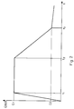
- FIG. 1 shows various temporal profiles of pressures during a braking operation.
- an operating element for example the position and duration of the application of the position of a brake lever or the duration of actuation of a button
- a setpoint A target for the pilot pressure of the relay valve is formed by electronic means. Details of this setpoint formation are described in the aforementioned EP-A-0.152.958.
- this value drops in a time-linear manner, starting from a control operating pressure of, for example, 5 bar, until the setpoint of the selected braking level is reached. This value is then kept constant until a different braking level or release of the brakes is selected.
- the pneumatic pilot pressure is adjusted to the A target value using an electro-pneumatic converter.
- the relay valve then tracks the HL pressure to the value A target with a time delay.
- the HL-pressure thus drops according to an exponential function from, according to curve HL is the Fig. 1.
- the HL pressure is measured by a pressure transducer and an electrical signal HL is the "train model" as the input value provided .
- a simulation HL m of the HL pressure is formed in the train model. Starting from the control operating pressure, the value of HL m is first reduced by a constant value dHL 1 to simulate a light-off behavior.
- dHL1 is, for example, 400 mbar. From this value, HL m is linear with a gradient (slope) that is inversely proportional to the total volume of the HL.
- this volume is divided into integer blocks, so that the gradient of HL m is then inversely proportional to the number of HL blocks AH 1.
- This slope constant ensures that in the initial phase of braking, the value of HL m is greater than the actual value HL Is.
- HL m is tracked by HL ist , which is done arithmetically by a maximum query.
- the minimum value HL min of HL m is stored continuously and evaluated at certain times in an adaptive learning process.
- a target pressure C is intended for the brake cylinder pressure to that of the C-pressure C m is tracked via a timing element in the train model of the actual value is determined in dependence on the instantaneous HL depressurization dHL and the maximum possible C-pressure C max. If the R containers are exhausted, C m is built up to the maximum possible R pressure R max , which achieves pressure equalization.
- dHL UREFge - HL m ;
- C. should MIN (C Max , (dHL * 3 - 0.4 bar)).
- the maximum possible build-up gradient for C m is limited to a constant value of, for example, 0.666 bar / s.
- the course of the simulated C pressure is thus a function of the build-up gradient and the maximum possible pressure R max in the R containers.
- the course of the pressure in the R containers is then determined from the C pressure course of the model.
- the volumes of the brake cylinders and the R-container are in a compiled train in a constant ratio F1 to each other (eg factor 5), which can vary depending on the type of car. Accordingly, a C pressure rise dC m causes a proportional R pressure drop dR m .
- No special time function therefore has to be specified for the R pressure drop if it is coupled with the C pressure build-up.
- the minimum R pressure R min reached is also stored and evaluated in the learning process.
- a release process following a braking process is described below.
- the following basic considerations apply here: As long as the simulated HL pressure HL m is below the simulated R pressure R m , the entire inflowing air volume is replenished exclusively in the HL. Only when the HL pressure HL m by a predetermined amount dR2 slightly larger (for example 30 mbar) than the R print R m is, the R-container of the HL are fed and R print R m is then treated with the HL pressure HL m carried. (The prerequisite for this is that the brake pressure requirement UREF is greater than the simulated R pressure R m .) From this point in time, the replenished air volume is divided between the HL and the R containers. On the basis of this criterion it can be distinguished whether only the HL or together the HL and the R containers are refilled.
- the pressure build-up in HL is determined in the train model based on the measured value for the replenished air volume.
- the HL block length is selected so that a volume of 1 l of relaxed air is required for a pressure increase of HL m by a certain amount, for example 10 mbar. Every time the differential pressure sensor at the orifice detects in connection with the volume integration that the given number of HL blocks the volume for increasing the HL pressure has flowed in by the predetermined amount of, for example, 10 mbar, the value of HL m is increased by this amount.
- the C-pressure reduction in the model is carried out to a function of the time profile of C, which is a function of DHL.
- dHL is the difference between the HL pressure before the start of braking minus the current HL m .
- C m follows the value C target according to an e-function, taking into account the natural time of the valves. In the model, this e-function is simulated by four straight lines.
- the actually replenished air volume ⁇ V is determined by volume integration from the measured value of the flow sensor (differential pressure measurement), which monitors the replenished air to the HL.
- the flow sensor differential pressure measurement
- separate pressure transducers are provided on both sides of a flow orifice or throttle point.
- the flow of air (or air mass flow) can be determined from the difference between the measured values of these two pressure sensors if the other parameters are known.
- the volume of relaxed air dV that flows in per time unit (time cycle) is a function of this pressure difference and the feed pressure HB from the main tank.
- other known measuring sensors can also be used, with which a volume or mass flow of a flowing gas can be determined.
- a calibration curve for the difference signal of the two pressure sensors is stored in a table, HB pressure being optionally selected as the parameter. Depending on the effort, several calibration curves for different HB pressures can also be saved. Under control of a time cycle, the measured differential pressure can then be converted directly into a flowed volume of relaxed air dV.
- the electronic train model is used either the pressure build-up of the HL pressure or the pressure build-up of the HL pressure in combination with the pressure build-up of the R pressure is determined.
- the A-chamber target pressure UREF is raised during the release process. If partial loosening is involved, it must be checked whether the new A-chamber set pressure is above the current R-tank pressure R m , since the R-tanks are only vented in this case. If this is not the case, only the HL is filled up.
- the HL block length or the number of HL blocks AHL is chosen so that a certain volume (eg 1 liter) of relaxed air per HL block is required for a certain pressure increase (eg 10 mbar).
- a certain volume eg 1 liter
- a certain pressure increase eg 10 mbar
- KL block and R block 1: 8
- eight times the volume (i.e. 8 liters) of relaxed air is required to increase the pressure of the R tank in a block by the same amount (10 mbar).
- the VSZUG value is determined as follows:
- VSZUG [MIN (UREF, UREFge) - HL m ] * 3 * AHL + [MIN (UREF, UREFge) - (R m + dR2)] * 24 * AR.
- AR is the number of R blocks; dR2 is the pressure difference by which the HL pressure must be greater than the pressure in the supply air tanks in order to vent the R tanks; this value is approximately 30 mbar).
- the increase "OVER" that is actually applied to the A-chamber set pressure is only built up to the value Ü1 in the case of full eyelets via a timing element with a predetermined linear build-up gradient (for example 1.6 bar / s) and then kept constant for a predetermined period of time t u .
- a timing element with a predetermined linear build-up gradient (for example 1.6 bar / s) and then kept constant for a predetermined period of time t u .
- UR is reduced from U1 to U2 via a second timer.
- the degradation gradient of this second timing element is selected such that any rapid brake accelerators that are present do not respond.
- the degradation gradient is, for example, 0.333 bar / s.
- the increase "OVER" is reduced to zero via a third timer, so that then only the control operating pressure is present as the A-chamber setpoint.
- the degradation gradient of the third timer is set so flat that the brake valves on the individual cars do not respond.
- the time period t ü during which the cant Ü1 is applied is determined in two stages:
- the position of the brake lever delivers a cant reference time via a stored table, the actual cant target time with a via a timing element predetermined gradient is tracked.
- the cant Ü1 should not be present for the entire period t ü .
- the time required for the breakdown from Ü1 to Ü2 is therefore partly taken into account.
- the time for the set-up is measured according to Ü1, this time is multiplied by a constant factor (eg factor 2) and the product is subtracted from t ü .
- a constant factor eg factor 2
- the HL and the R tank (s) are filled up shortly after reaching Ü1 and the measured differential pressure dp approaches zero.
- the differential pressure is therefore compared against a lower threshold value dp min1 (of 50 mbar, for example). If the differential pressure dp falls below this threshold value for a certain duration (eg 1 sec), the reduction from Ü1 to Ü2 begins immediately.
- the first two conditions must be fulfilled before the third. As soon as the third condition is met, the learning process is carried out.
- the learning process is based on a comparison between the air volume actually flowing into the train and the air volume expected by the model size.
- the volume of air that has actually flowed in has already been used to increase the model pressures of HL and R containers. If the model size is selected correctly, the HL and R pressures must have reached the value specified by UREF or UREFge. If the actual inflow volume and the inflow volume calculated by the model differ from each other, the train is longer or shorter than assumed in the model. The values AHL and / or AR must then be corrected.
- a measure of the deviation of the train model from the actual train size is VSZUG at the time of the learning process.
- VSZUG specifies the air volume that still needs to be replenished in order to completely release the train or that has been replenished too much in relation to the train model.
- the sign of VSZUG can be used to determine whether the train model has to be enlarged or reduced, while the amount of VSZUG provides information about the value by which the block numbers AHL and / or AR have to be changed. If VSZUG is equal to ZERO, the model and reality are completely the same. The model is therefore correct; an adaptive learning process for the model sizes AHL and / or AR is not to be carried out.
- VSZUG If VSZUG is positive, then the actual inflow of air is smaller than expected. The model is too large and needs to be downsized. If VSZUG is negative, then the volume of air actually flowed in is greater than expected. The model is too small and needs to be enlarged. With HL min alone or in combination with R min as well as UREF or UREFge, the air requirement for releasing longer or shorter trains can be calculated retrospectively. It is determined for how many HL and / or R blocks the value of VSZUG available at the time of the learning process is still sufficient or was already too large to set the target pressure.
- the number of AHL of the HL blocks may be changed for this recalculation. If, on the other hand, HL and the R containers have been refilled, the number of AHL and AR can be changed together or, in certain individual cases, only AR. The size of the change depends on how many more (or fewer) HL and / or R blocks could have been filled with the value of VSZUG still remaining when the learning process was initialized.
- the learning process is carried out iteratively with different block numbers.
- AHL and / or AR are changed in steps of 0.5 blocks.
- the first question is whether only HL or HL and R blocks have been filled. If this query shows that only HL blocks have been filled, a check is carried out to determine whether VSZUG is greater or less than zero. If VSZUG is greater than zero, a value VSZUG HL1.5 is calculated with an HL block number AHL of 1.5, ie a value that corresponds to the air volume for filling 1.5 HL blocks. The block number of the R containers is not changed.
- VSZUG is then greater than VSZUG HL1.5 , the number of HL blocks is reduced by 2.
- VSZUG is smaller than VSZUG HL1.5 , a further value of VSZUG, namely the value VSZUG HL0.5, is calculated, which corresponds to the air volume required for filling 0.5 HL blocks. It is then checked whether VSZUG is larger or smaller than VSZUG HL0.5 . If this is the case, the number of HL blocks is reduced by 1. If this is not the case, the number of HL blocks is left constant.
- VSZUG is less than zero, the sign is changed to simplify the calculations for the following calculations. The same calculations and tests are then carried out as described above. If VSZUG (with a changed sign) is larger than VSZUG HL1.5 , the number of HL blocks is increased by 2. If this condition is not met, the comparison with VSZUG HL0.5 is carried out again. If VSZUG is greater than VSZUG HL0.5 , the number of HL blocks is increased by 1. If this condition is not met, the number of HL blocks is left constant.
- a value VSZUG Buch0.5 air volume for 0.5 HL and R blocks each
- VSZUG R0.5 air volume for loosening 0.5 R blocks. It is then checked whether VSZUG is greater than VSZUG R0.5 . If this is the case, AR is increased by 1. If this is not the case, all sizes are left constant.
- the learning process can not only be carried out with a complete loosening but also after a partial loosening, in which case a braking stage is also activated.
- the partial dissolving process must of course be completed, ie practically no more air can be fed into the HL when the learning process is carried out, which is ensured by the differential pressure measurement and the above-mentioned threshold value dp min2 .
- HL pressure When fully loosening, the HL pressure is reduced in the model with the A-chamber set pressure UREF to standard operating pressure.
- HL m MAX (UREF - dHL2, control operating pressure).
- dHL2 is a pressure difference that is present when the train is not completely filled. For example, it is 20 mbar.
- HL m UREF
- HL min HL m C.
- the block numbers AHL and AR are set to a predetermined value, which corresponds to an average mean train length. After a few braking and releasing processes or more precisely learning processes following releasing processes, these numbers will then have adapted to the actual train length.
- a train separation can also be detected very precisely.
- a very long train is assumed in the model and the time course of the actual filling process is compared with a time course specified for the complete release of this long train.
- the measured differential pressure is used as a control value.
- a starting value DP kon for the monitoring of train separation is continuously recalculated in the braked state. It is a function of HL min , R min and UREFge:
- DP kon [(UREFge - HL min ) * 3 + (UREFge - R min ) * 24] * 9/256 + 33.
- This calculation applies to the release of a very long train with a high air requirement. If the learning process has progressed so far that a more precise statement about the train configuration can be made, AHL and AR are taken into account when calculating the start value. This enables the train to be monitored more optimally.
- a check for train separation takes place in the released state as soon as the pressure increase "ABOVE" has been reduced to Ü2. If this condition is met, the calculated start value DP kon is reduced over two time elements to a minimum value dp min3 (eg 100mbar).
- the degradation gradient is 150 s / bar, for example, as long as DP kon is greater than 300 mbar. If DP kon is between 300 mbar and DP min3 , the gradient is 600 s / bar.
- the measured differential pressure dp is compared with this control pressure DP kon . If the control pressure is exceeded for a certain period of time, a signal "train separation recognized" is output.
- the lower limit value DP min3 is selected so that the make-up caused by leaks is not recognized as train separation. A train separation that takes place at normal operating pressure, however, is recognized immediately.
- a further modification of the invention provides in a subroutine to check whether sudden, major changes occur after several braking and releasing processes, after which the train model has adapted to the actual train length. In this case, an alarm is given to prevent the train model from moving towards a Automatically adjusts train shortening. Such a shortening of the train could also occur by unintentionally shutting off the HL behind the locomotive.
- FIG. 4 shows the formation of the A-chamber setpoint.
- the actuation of an operating process for example a driver's brake lever, is sensed and, in accordance with EP-A-0.152.958, is converted to a first value UBV by means of a simulation 1 of a response behavior and by means of timing elements 2 which determine the gradient or the steepness of a signal change a summer 3 is supplied.
- the switched-on brake lever value UB1 is converted via a (stored) table and a timing element (59 ??) into the target boost time t ü .
- a plurality of assemblies 4, 5 are provided for emulating an equalizer function, which supply an equalizer value UAG to the summer 3.
- Certain correction variables U corr and U Vietnamese, which are not of interest here, are also fed to the summer 3.
- a summation value "OVER" is supplied to the summer 3, which is formed in a function block 6 from the electronic train model 7.
- Other output variables of the electronic train model are used for the control of train separation (14).
- the output signal UREF of the summer 3 is a measure of the request for the pilot pressure and thus the HL pressure.
- the value of UREF pending at the start of braking is stored in a memory 8 as UREFge.
- the value UREF is processed in a controller 9 to a setpoint value U setpoint which is fed to an analog converter which, by actuating valves, sets the A pressure (pilot pressure) which corresponds to the relay valve. is fed to the braking system.
- the controller contains a comparator 10 which subtracts a signal corresponding to the measured HL pressure from UREF.
- the output signal of the subtractor 10 is fed to a summer 11, in which a differential pressure value is multiplied is summed with a factor K1.
- the pressure difference dp is measured by two pressure transducers on both sides of a flow orifice in the make-up branch for the HL.
- the value dp is therefore a measure of the flow speed of the replenished air.
- the output of the summer is fed to the actual controller 12, which here has a PI characteristic (proportional-integral).
- the output of the controller 12 is fed to a summer 13 and added to the value UREF, the sum then being the target value U soll for the analog converter.
- Fig. 5 illustrates the input and output variables for the train model 7 and the control for train separation 14.
- Input variables are measured values of the HL pressure and the mentioned differential pressure dp.
- Other input variables are the values UREF and UREFge.
- train model 7 these four input variables and internally stored values are used to form target variables Ü1 and Ü2 for the pressure increase during the release process.
- the actual superelevation value "OVER" is then formed in block 6 of FIG. 4 from the quantities U1 and U2.
- Further output values of the train model 7 are HL min and R min , which together with the measured value dp and the value UREFge are fed to a control device 14 for monitoring train separation.
- the values HL min and R min are values of the HL and R pressure determined by the train model, from which the release process was started.
- FIG. 6 shows a more detailed block diagram of the train model 7 of FIG. 5.
- the train model essentially simulates three pressures, namely the HL pressure HL m , the R tank pressure R m and the Brake cylinder pressure C m . Since these replicas are formed differently when braking and releasing, different blocks 15 and 16 are shown in the block diagram.
- the block 15 forms the model variables HL m , R m , C m and the from the external input variables HL ist , UREFge and UREF and the internal variable AHL Sizes HL min and R min .
- the sum ⁇ V of the volume replenished since the beginning of the dissolving and a value dV of the volume currently replenished per unit of time are determined from the measured value dp by means of a volume integration 17 and supplied to block 16.
- the internal variables AR and AHL are also taken into account. From these values, on the one hand, the value VSZUG required for the adaptive learning process, which represents the air requirement still required for the current release process, and the superelevation values Ü1 and Ü2 are formed.
- the number of HL and R blocks AHL and AR is determined from VSZUG, UREF and UREFge as well as HL min or HL min and R min when a signal (from volume integration 17) is given .
- the measured value HL is and the target variable UREF are fed to a maximum value selection 19 to form an intermediate value.
- HL m tracks this intermediate value in a time-linear manner in a block 20, the gradient depending on the stored number of HL blocks AHL.
- the output of block 20 is the model size HL m .
- the minimum value of HL m is stored in an additional memory 21.
- the difference between UREFge and HL m is formed and multiplied by a factor K c .
- this multiplied difference value is compared with the maximum C pressure C max , the minimum value then the target pressure C should represent the train model.
- C m is formed from C target , C m not being allowed to be greater than R m , since pressure equalization is then achieved.
- the value R m is formed from C m by multiplication by a constant factor (eg factor 5) in a multiplier 24.
- the current minimum value of R m is stored in a further memory 25.
- the blocks shown in FIG. 8 collectively correspond to block 15 in FIG. 6.
- the measured value HL is and the target variable UREF are - as in FIG. 8 - fed to the maximum value selection 19 to form the intermediate value HL zw .
- a subtractor 49 the value HL m (old) from the previous clock cycle is subtracted from the intermediate value to form a value ⁇ HL s .
- this value ⁇ HL s is increased linearly in time, the number of HL blocks AHL serving as a parameter.
- a value ⁇ HL m then appears at the output of the block, which is a measure of the amount by which the HL m present at the previous clock cycle must be reduced in order to obtain a new value HL m (new) .
- the value ⁇ HL m is therefore subtracted from HL m (old) in a subtractor 50.
- the output of the subtractor 50 then provides the value HL m (new) .
- a further subtractor 51 the output of the subtractor 50 is subtracted from the stored value of the braking request UREFge, this difference UREFge minus HL m (new) being increased in a time-linear manner in a block 52 with a predetermined gradient, but with a limitation to the maximum value C max .
- the output of block 52 represents signal C soll , which is fed to a minimum value selection circuit 53.
- the circuit 53 selects the minimum of C nominal and R m (new) and passes this on to a subtractor 54 where the value C m (old) is subtracted. This difference is increased in a time-linear manner in a further circuit 55 to form a value ⁇ C m.
- This value ⁇ C m indicates the amount by which the C model pressure C m must be increased per time cycle. Accordingly, the values ⁇ C m and C m (old) are fed to a subtractor 56, the output signal of which is the new value of C m . Since the model pressures C m and R m are coupled to one another via a constant factor, the value ⁇ C m is also proportional to the reduction in the model pressure R m to be carried out per time cycle by this factor.
- the output of the circuit 55 is connected to a multiplier 57 which multiplies the value ⁇ C m by this constant factor, from which one then obtains a ⁇ R m , ie a value which indicates the amount by which the model pressure R m are reduced per time cycle got to.
- the output signal of the multiplier 57 is therefore subtracted in a subtractor 58 from the previous value of the R model pressure R m (old) to form the new value R m (new) .
- the minimum selection circuit 53 ensures that the model pressure C m cannot become greater than the reservoir pressure R m . 8a correspond to those of FIG. 8.
- block 16 of FIG. 6 is resolved in more detail.
- a value of the flow velocity of the air replenished during loosening is determined by querying a memory 26 which contains calibration curves for the pressure transducers and possibly different make-up pressures (HB pressures). From this value, under control of the timing, a value of the volume dV replenished per timing is formed in block 27.
- the values of dV are added up in a digital integrator 28, from which the value ⁇ V is contained, which represents the air volume that has actually been replenished since the start of the solution.
- the value dV is compared in a comparator 29 with a threshold value dV min . If dV falls below this threshold value for a certain period of time, the dissolving process is considered to be completed, since the volume then replenished is so small that it does not lead to an effective pressure increase in the HL pressure.
- the output signal of the comparator 29 then opens a switch 29 ', whereby the summer 28 is deactivated. Furthermore, this output signal is passed on to the "learning process" block, which is then started after the release process has ended.
- UREF is greater than R m and whether Hl m is still below the value R m at the end of the braking process lies.
- the latter can be done, for example, by forming the difference R m -HL m from a subtractor 30 and comparing it in a threshold switch 31 with the reference value dR2 (eg 30 mbar). If HL m is still below R m , a switch 32 is hereby controlled so that dV is only used to increase the model pressure HL m . The increments dV are then multiplied by a factor in a block 33 and added up.
- This factor corresponds to the gradient for the increase in HL m and depends on the number of HL blocks AHL.
- a signal then appears at the output of block 33, which represents the pressure increase dHL achieved.
- this value is added to the existing model pressure HL m, from which it then obtains the rising pressure in solving model HL m. From this value, the C pressure reduction is determined in a block 35 according to a time function.
- This tent function is theoretically an e-function, which is approximated here by four straight sections.
- the values for VSZUG, Ü1 and Ü2 are then determined from these two values in accordance with the block diagram of FIG. 10.
- the values UREF and UREFge serve as further input variables.
- the minimum of these two values is determined in a minimum selection 39 and fed to a subtractor 40, where the value HL m is subtracted.
- the resulting difference value ⁇ HL is multiplied in a multiplier 41 by a constant factor and in a further multiplier by the current number of HL blocks.
- the difference between the minimum of UREFge and UREF minus R m is formed and multiplied in multipliers 43 and 44 by a constant factor or the number of R blocks AR.
- the factor of the multiplier 43 can be predetermined arbitrarily.
- the learning process has more favorable starting conditions if this factor approximates the volume ratio between the volume of the R containers of a block and the volume of the HL line of a block.
- This ratio is about 1: 8 for standard freight trains, for modern passenger coaches where the HB line (make-up line) is connected by the From the point of view of the HL, the number AR, on the other hand, is ZERO, since the air volume to be replenished via the HL to the R-boxes is ZERO.
- the output values of the multipliers 42 and 44 are added to a totalizer 45, which then gives the value VSZUG for the volume to be replenished.
- a value for U2 is then formed from this value in a block 46 in accordance with a predetermined characteristic curve.
- the value Ü1 and Ü2 are in a fixed relationship to one another (eg factor 5), the value Ü1 is formed from Ü2 in a multiplier 47. From these two values, the actual superelevation value "OVER" is then formed in block 6 of FIG. 4, by which the pilot pressure is to be additionally increased in order to release more quickly.
- FIG. 11 shows a block diagram for the learning process.
- VSZUG can be positive or negative.
- the values HL min and R min are used as input variables, from which, analogously to the outputs of the multipliers 42 and 44 of FIG. 10, increments of air quantities replenished for HL and / or R blocks for +/- half or one and a half block lengths can be determined.
- V HL0.5 which corresponds to the volume required for filling half a HL block
- V HL1.5 corresponding to this air volume for one and a half HL blocks
- V R0.5 corresponds to the volume to be replenished for the R containers at half
- V R1.5 corresponding to this volume for one and a half R blocks.
- Corrected values for VSZUG are then formed in summers 45 'and 45', which functionally correspond to adder 45 in FIG. 10, for correspondingly changed block numbers.
- FIG. 9 it is again checked here whether the volume to be replenished is used for filling HL alone or for HL and the R containers.
- the variables UREF and R min are compared (cf. subtractor 30 'and threshold switch 31'). If this comparison shows that only HL is filled, the output of the comparator 31 'controls a switch 32', which corresponds in terms of function to the switch 32 in FIG. 9. If it is found in the comparison that only HL is topped up, the switch is set to the zero position so that no volumes to be replenished are calculated for the R containers.
- the actual learning process is then carried out from the ascertained variables in a computing block 48, in which the block numbers AHL and / or AR are compared with the values modified by the changed block numbers on the basis of the comparison of the sign and amount of VSZUG. After completion of the learning process in block 48, the possibly changed block numbers AHL and AR are output as new output values for the next cycle.
- Fig. 12 shows again in more detail a flow diagram of the operation of the train model for the simulation of the different pressures. This figure, like the other flowcharts, is intended to more clearly illustrate the sequences described above. 13 accordingly shows the volume integration. 14 shows the learning process. 15 finally shows the monitoring for train separation.
Landscapes
- Engineering & Computer Science (AREA)
- Transportation (AREA)
- Mechanical Engineering (AREA)
- Braking Systems And Boosters (AREA)
- Regulating Braking Force (AREA)
- Control Of Driving Devices And Active Controlling Of Vehicle (AREA)
- Valves And Accessory Devices For Braking Systems (AREA)
- Cosmetics (AREA)
Claims (14)
- Procédé de commande adaptative de freinage pour des freins à air comprimé à action indirecte, qui possèdent un robinet de frein électropneumatique du mécanicien comportant un organe de commande pour le réglage d'une valeur de consigne (UREF) pour la pression de freinage, une conduite d'air principale (HL), une soupape relais raccordée à cette conduite, plusieurs réservoirs d'air raccordés à la conduite d'air principale (HL), ainsi que des premier et second capteurs de mesure, le robinet de frein du mécanicien produisant une pression de commande pilote (pression A) pour la soupape relais, comportant les phases opératoires suivantes :a) la mesure du volume d'air (ΣV) introduit dans la conduite d'air principale (HL) lors du desserrage du frein;b) la mesure de l'air comprimé (HList) dans la conduite d'air principale (HL);c) la modification de la pression de commande pilote (pression A) en fonction des grandeurs mesurées (ΣV, HList),caractérisé par les autres phases opératoires suivantes :d) à partir des valeurs mesurées du volume d'air introduit (ΣV) et de la pression d'air (HList) dans la conduite d'air principale (HL) sont produits, par une unité de simulation du train (7), des signaux électriques, qui simulent la variation dans le temps au moins de la pression (HLm) dans la conduite d'air principale et de la pression (Rm) dans les réservoirs d'air, sur la base de fonctions prédéterminées;e) à partir des signaux électriques (HLm et Rm), qui simulent au moins la pression dans la conduite d'air principale et la pression dans les réservoirs d'air, à partir d'un signal (UREF) dérivé de l'organe de commande et
à partir des valeurs mémorisées (AHL, AR), qui correspondent à un volume supposé de la conduite d'air principale et des réservoirs d'air, est formé un signal (VSZUG), qui correspond au volume d'air devant être encore introduit en supplément pendant un processus de desserrage,f) à partir du signal (VSZUG) du volume d'air devant être introduit en supplément est formée une valeur de correction (ÜBER), qui détermine de quelle valeur la pression de commande pilote réglée pour le desserrage est accrue, etg) à la suite d'une opération de desserrage la valeur (ΣV) du volume mesuré devant être introduit en supplément et la valeur (VSZUG) du volume déterminé devant être introduit en supplément sont comparées et, dans le cas d'un écart entre ces valeurs, la valeur des grandeurs mémorisées (AHL, AR) est corrigée. - Procédé de commande adaptative de freinage suivant la revendication 1, caractérisé par le fait que la variation de pression, déterminée dans l'unité de simulation électronique du train (7), de la pression (HLm) dans la conduite d'air principale est réduite d'une manière linéaire dans le temps (éventuellement à la suite d'une réduction brusque de la pression) à partir d'une pression (HList) dans la conduite d'air principale, qui est présente au début d'un freinage, la pente de cette chute de pression simulée dépendant de la grandeur (AHL) mémorisée et étant choisie de manière que la chute de pression simulée (HLm) d'une opération de freinage est plus plate que la chute de pression effective HList et que la chute de pression simulée (HLm) est la valeur maximale obtenue à partir de la variation de pression effective (HList) et de la variation de pression qui chute selon une variation linéaire dans le temps.
- Procédé de commande adaptative de freinage suivant la revendication 2, caractérisé par le fait que la valeur minimale (HLmin), obtenue pendant une opération de freinage, de la variation de pression simulée (HLm) est mémorisée.
- Procédé de commande adaptative de freinage suivant la revendication 3, caractérisé par le fait que pour la détermination de la pression simulée (Rm) dans les réservoirs d'air, une valeur (UREFge) du signal de demande de freinage, mémorisée au début du freinage, et diminuée de la pression HL simulée (HLm) et en outre éventuellement d'une valeur affectée de valeurs de correction multiplicatives et additives, ((UREFge-HLm)*3-0,4 bar), est comparée à une valeur mémorisée, qui correspond à la pression maximale possible (Cmax) présente dans les différents cylindres de frein, la plus petite des deux valeurs comparées (Csoll) étant accrue par l'intermédiaire d'un circuit de temporisation (23) avec un gradient prédéterminé, et que lors de chaque accroissement de cette valeur, d'un premier montant prédéterminé, la pression simulée (Rm) dans les réservoirs d'air est réduite d'un second montant prédéterminé.
- Procédé de commande adaptative de freinage suivant la revendication 4, caractérisé par le fait que la valeur minimale (Rmin) de la pression simulée (Rm) dans les réservoirs d'air est mémorisée dans une mémoire (25).
- Procédé de commande adaptative de freinage suivant une ou plusieurs des revendications 2 à 5, caractérisé par le fait que lors d'une opération de desserrage, le volume d'air, introduit effectivement en supplément dans la conduite d'air principale, est déterminé par mesure d'une pression différentielle (dp) au niveau d'un diaphragme d'écoulement en coopération avec une courbe d'étalonnage mémorisée ou calculée, tandis qu'en outre un contrôle est exécuté pour savoir si le volume d'air (dB) introduit en supplément par une unité de temps dans la conduite d'air principale, est ou non supérieur à une valeur minimale prédéterminée (dVmin), et que dans l'unité de simulation électronique de traction, les volumes d'air (dB) introduits en supplément par unité de temps sont additionnés dans un additionneur (28), en fonction de cette comparaison.
- Procédé de commande adaptative de freinage suivant la revendication 6, caractérisé par le fait que pendant une opération de desserrage, un contrôle est exécuté pour savoir si la pression de freinage demandée (UREF) et la pression simulée (HLm) dans la conduite d'air principale sont inférieures à la pression simulée (Rm) dans le réservoir d'air, que lorsque cette condition est satisfaite, le volume d'air (dB) introduit en supplément par unité de temps est pondéré par une valeur prédéterminée, qui correspond à la valeur mémorisée (AHL) pour le volume supposé de la conduite d'air principale, ce qui permet de déterminer des incréments (dHL) pour l'accroissement de la pression simulée dans la conduite d'air principale par unité de temps, et que lorsque la condition n'est pas satisfaire (HLm < Rm) , les valeurs du volume d'air (dB), qui est introduit en supplément par unité de temps, sont pondérées par deux facteurs de pondération (AHL, AR) , dont la somme totale correspond au volume supposé de la conduite d'air principale et des réservoirs d'air, ce qui permet de déterminer des valeurs d'incrémentation pour l'établissement commun de la pression de la conduite d'air principale et de la pression des réservoirs d'air.
- Procédé de commande adaptative de freinage suivant une ou plusieurs des revendications 1 à 7, caractérisé par le fait que lors d'une opération de desserrage, la valeur actuelle de la pression simulée (HLm) dans la conduite d'air principale est soustraite de la valeur plus faible tirée du signal de demande de freinage (UREF) et est soustraite (soustracteur 40) du signal de demande de freinage (UREFge) mémorisée au début du freinage, est multipliée (41) par un premier facteur constant et est multipliée (42) par la valeur mémorisée (AHL) pour le volume supposé de la conduite d'air principale, de façon analogue la différence entre le signal minimum de demande de freinage et la pression simulée (Rm) des réservoirs d'air est multipliée par un facteur constant (multiplicateur 43) et par un facteur (multiplicateur 44), le dernier facteur correspondant au volume supposé des réservoirs d'air (AR), et que les deux produits ainsi obtenus sont additionnés dans un additionneur (45) pour former la valeur (VSZUG), qui représente le volume d'air (VSZUG) devant être introduit en supplément.
- Procédé de commande adaptative de freinage suivant la revendication 8, caractérisé par le fait que deux valeurs limites (Ü1, Ü2) pour l'accroissement possible de pression pendant une opération de desserrage sont déterminées à partir de la valeur (VSZUG) pour le volume d'air devant être encore introduit en supplément, sur la base d'une fonction prédéterminée (46).
- Procédé de commande adaptative de freinage suivant la revendication 9, caractérisé par le fait que l'accroissement de pression, qui doit être superposé à la pression de commande pilote (UREF) lors du desserrage, est accru selon un accroissement linéaire dans le temps jusqu'à la valeur limite supérieure (Ü1) avec un premier gradient, que cette valeur limite supérieure est maintenue pendant une durée prédéterminée (tü), puis est réduite d'une manière linéaire dans le temps avec un second gradient jusqu'à la valeur limite inférieure (u2) et, à partir de là, est réduite jusqu'à la valeur nulle avec un troisième gradient plus faible, le troisième gradient étant choisi suffisamment faible pour que les soupapes de commande de frein des différentes voitures ne répondent pas à la réduction de pression qui apparaît alors.
- Procédé de commande adaptative de freinage suivant la revendication 10, caractérisé par le fait que la durée prédéterminée (tü) est déterminée en fonction de l'actionnement (palier de freinage et durée de l'activation dans le palier de freinage) de l'organe de commande de freinage.
- Procédé de commande adaptative de freinage suivant l'une des revendications 1 à 11, caractérisé par le fait qu'à la suite d'une opération terminée de desserrage, on vérifie si la différence entre le volume d'air introduit effectivement de façon supplémentaire et le volume d'air déterminé (VSZUG), devant être encore introduit en supplément, est nulle et que, dans le cas où cette condition n'est pas satisfaite, des valeurs corrigées en fonction du signe de cette différence (VHL0.5, VHL1.5, VR0.5, VR1.5, VZUGO.5, VZUG1.5) sont déterminées, ces valeurs fixant, conformément à des sauts prédéterminés, quelle quantité d'air est nécessaire pour le remplissage ou le vidage de nombres prédéterminés (0,5, 1,5) de sections (HL) et/ou de réservoirs d'air (blocs HL et/ou R) pour obtenir la pression commandée (UREF), que ces valeurs déterminées et corrigées sont comparées à la valeur (VSZUG), déterminées à la fin de l'opération de desserrage, pour le volume devant être encore introduit en supplément, et qu'en fonction de cette comparaison, les valeurs (AHL et/ou AR) pour le volume supposé de la conduite d'air principale et/ou des réservoirs d'air sont modifiées pour le cycle immédiatement suivant de freinage et de desserrage.
- Procédé de commande adaptative de freinage suivant la revendication 12, caractérisé par le fait qu'un signal d'alarme est produit lorsque des modifications des volumes supposés de la conduite d'air principale et/ou des réservoirs d'air dépassent une valeur prédéterminée.
- Procédé pour la commande adaptative de freinage suivant une ou plusieurs des revendications 1 à 13, caractérisé par le fait qu'à la suite de la suppression de l'accroissement de pression (de Ü1 vers Ü2), une pression de contrôle (dPkon) est produite, que cette pression de contrôle est comparée à la pression mesurée (dP) dans la branche d'alimentation complémentaire pour la conduite d'air principale (HL), et qu'un signal d'alarme est produit lorsque la pression de contrôle (dpkon) est inférieure, pendant une durée prédéterminée, à la pression mesurée (dp).
Applications Claiming Priority (3)
| Application Number | Priority Date | Filing Date | Title |
|---|---|---|---|
| DE4013278A DE4013278A1 (de) | 1990-04-26 | 1990-04-26 | Adaptive bremssteuerung |
| DE4013278 | 1990-04-26 | ||
| PCT/DE1991/000318 WO1991016222A2 (fr) | 1990-04-26 | 1991-04-18 | Commande adaptative du freinage |
Publications (2)
| Publication Number | Publication Date |
|---|---|
| EP0526482A1 EP0526482A1 (fr) | 1993-02-10 |
| EP0526482B1 true EP0526482B1 (fr) | 1994-06-01 |
Family
ID=6405113
Family Applications (1)
| Application Number | Title | Priority Date | Filing Date |
|---|---|---|---|
| EP91907529A Expired - Lifetime EP0526482B1 (fr) | 1990-04-26 | 1991-04-18 | Commande adaptative du freinage |
Country Status (7)
| Country | Link |
|---|---|
| US (1) | US5405182A (fr) |
| EP (1) | EP0526482B1 (fr) |
| JP (1) | JP2846113B2 (fr) |
| AT (1) | ATE106334T1 (fr) |
| CA (1) | CA2081461A1 (fr) |
| DE (2) | DE4013278A1 (fr) |
| WO (1) | WO1991016222A2 (fr) |
Families Citing this family (20)
| Publication number | Priority date | Publication date | Assignee | Title |
|---|---|---|---|---|
| DE4312404A1 (de) * | 1993-04-16 | 1994-10-20 | Teves Gmbh Alfred | Fremdkraftbremssystem für Kraftfahrzeuge |
| DE4428929A1 (de) * | 1994-08-16 | 1996-02-22 | Wabco Gmbh | Verfahren und Einrichtung zur Druckregelung |
| US5480218C1 (en) * | 1994-09-15 | 2001-05-01 | Westinghouse Air Brake Co | Railway brake pipe bracket with access ports |
| CA2148424C (fr) * | 1995-03-02 | 2000-04-18 | James E. Hart | Appareil d'essai automatique de repartiteur de freinage de wagon de chemin de fer |
| US5662389A (en) * | 1996-09-10 | 1997-09-02 | New York Air Brake Corporation | Variable load EP brake control system |
| DE19833279A1 (de) * | 1998-07-24 | 2000-02-10 | Deutsche Bahn Ag | Einrichtung zur Überwachung der Zugvollständigkeit, sowie der Überprüfung der Bremsprobe bei lokbespannten Zügen |
| DE19918995A1 (de) * | 1999-04-27 | 2000-11-16 | Daimler Chrysler Ag | Lenk- und Bremssystem für ein Fahrzeug |
| DE19931163C2 (de) * | 1999-07-06 | 2002-01-17 | Knorr Bremse Systeme | Verfahren zum Lösen der Bremsen eines Druckluftbremssystems mittels eines Füllstoßes |
| DE10029125B4 (de) * | 2000-06-14 | 2004-08-26 | Siemens Ag | Alarmeinrichtung für eine druckluftgesteuerte Bremsanlage eines Fahrzeugs |
| DE10207803B4 (de) * | 2002-02-25 | 2008-11-27 | Knorr-Bremse Systeme für Nutzfahrzeuge GmbH | Druckregler einer Druckluftversorgungseinrichtung für eine Bremsanlage eines Kraftfahrzeugs und Verfahren zum Befüllen einer Kraftfahrzeug-Bremsanlage mit Druckluft |
| US8013550B1 (en) | 2003-11-26 | 2011-09-06 | Liontech Trains Llc | Model train remote control system having realistic speed and special effects control |
| EP2371586A1 (fr) * | 2010-03-22 | 2011-10-05 | Haldex Brake Products AB | Procédé de contrôle de l'actionnement fluidique d'un frein ou système de suspension |
| KR101260283B1 (ko) | 2010-09-20 | 2013-05-03 | 주식회사 만도 | 안티록 브레이크 시스템의 제어방법 |
| DE102011078890A1 (de) * | 2011-07-08 | 2013-01-10 | Robert Bosch Gmbh | Überwachungsvorrichtung für zumindest eine Untereinheit eines hydraulischen Bremssystems und Verfahren zum Untersuchen einer Funktionsfähigkeit zumindest einer Untereinheit eines hydraulischen Bremssystems |
| US8880314B2 (en) * | 2012-11-14 | 2014-11-04 | General Electric Company | Brake monitoring systems and methods |
| CN105235706A (zh) * | 2015-10-19 | 2016-01-13 | 济南大学 | 补空压的电空制动速充风装置的应用 |
| CN112319537B (zh) * | 2020-10-27 | 2022-05-06 | 中车株洲电力机车研究所有限公司 | 列车空气制动状态实时评估方法、系统、存储介质 |
| CN112612234B (zh) * | 2020-12-23 | 2022-05-31 | 神华铁路装备有限责任公司 | 电空制动控制装置列车试验系统、方法、计算机设备及其可读存储介质 |
| CN114537361B (zh) * | 2022-03-22 | 2022-11-08 | 中车制动系统有限公司 | 制动控制系统部件故障预测方法 |
| CN115095584B (zh) * | 2022-05-30 | 2024-10-01 | 沈阳航天新光集团有限公司 | 一种基于AMESim的液路滑阀阀芯开度控制模型 |
Family Cites Families (7)
| Publication number | Priority date | Publication date | Assignee | Title |
|---|---|---|---|---|
| ZA80674B (en) * | 1979-02-20 | 1981-02-25 | Westinghouse Brake & Signal | Rail vehicle braking apparatus |
| DE3205846A1 (de) * | 1982-02-18 | 1983-08-25 | Knorr-Bremse GmbH, 8000 München | Fahrzeugbremsanlage, insbesondere hydraulische fahrzeugbremsanlage fuer schienenfahrzeuge |
| US4678241A (en) * | 1985-03-11 | 1987-07-07 | Nippon Air Brake Co., Ltd. | Equalizer discharge valve for a railroad car air brake system |
| IT1206909B (it) * | 1987-02-13 | 1989-05-11 | Wabco Westinghouse Spa | Le sistema di comando del freno automatico di veicoli ferroviari mediante trasmissione elettrica del segna |
| DE3805589A1 (de) * | 1988-02-23 | 1989-08-31 | Lucas Ind Plc | Verfahren und vorrichtung zum steuern einer bremsanlage fuer schwerfahrzeuge |
| US4859000A (en) * | 1988-08-15 | 1989-08-22 | Harris Corp. | Adaptive air brake control system |
| US4904027A (en) * | 1988-10-03 | 1990-02-27 | American Standard Inc. | Digital air brake control system |
-
1990
- 1990-04-26 DE DE4013278A patent/DE4013278A1/de not_active Withdrawn
-
1991
- 1991-04-18 WO PCT/DE1991/000318 patent/WO1991016222A2/fr not_active Ceased
- 1991-04-18 AT AT91907529T patent/ATE106334T1/de not_active IP Right Cessation
- 1991-04-18 EP EP91907529A patent/EP0526482B1/fr not_active Expired - Lifetime
- 1991-04-18 US US07/938,270 patent/US5405182A/en not_active Expired - Fee Related
- 1991-04-18 DE DE59101809T patent/DE59101809D1/de not_active Expired - Fee Related
- 1991-04-18 JP JP3506748A patent/JP2846113B2/ja not_active Expired - Fee Related
- 1991-04-18 CA CA002081461A patent/CA2081461A1/fr not_active Abandoned
Also Published As
| Publication number | Publication date |
|---|---|
| DE4013278A1 (de) | 1991-10-31 |
| JPH05506629A (ja) | 1993-09-30 |
| ATE106334T1 (de) | 1994-06-15 |
| WO1991016222A3 (fr) | 1991-11-28 |
| WO1991016222A2 (fr) | 1991-10-31 |
| DE59101809D1 (de) | 1994-07-07 |
| US5405182A (en) | 1995-04-11 |
| EP0526482A1 (fr) | 1993-02-10 |
| CA2081461A1 (fr) | 1991-10-27 |
| JP2846113B2 (ja) | 1999-01-13 |
Similar Documents
| Publication | Publication Date | Title |
|---|---|---|
| EP0526482B1 (fr) | Commande adaptative du freinage | |
| EP2079619B1 (fr) | Installation d'alimentation en air comprimé et procédé pour déterminer des paramètres de cette installation | |
| DE3990898C2 (de) | Druckluftbremsensteuerungssystem | |
| DE68918559T2 (de) | Anhängerbremsung in elektronisch gesteuerten Bremssystemen. | |
| DE3932245A1 (de) | Digitales druckluftbremsen-steuersystem | |
| DE19732884C2 (de) | Vorrichtung zur Steuerung des Bremsfluiddrucks in einem Fahrzeugbremssystem | |
| EP0224832A2 (fr) | Système de freinage électrique pour un véhicule | |
| DE19510522A1 (de) | Verfahren und Vorrichtung zur Steuerung bzw. Regelung der Bremsanlage eines Fahrzeugs | |
| DE4012167A1 (de) | Antiblockierregelsystem | |
| WO2019057615A1 (fr) | Système de freinage électro-pneumatique doté d'un mode de test pour le circuit de frein pneumatique de secours | |
| EP3455111B1 (fr) | Système de freinage à étalonnage automatique et procédé d'étalonnage automatique d'un système de freinage | |
| EP3068669B1 (fr) | Procédé et système de détection d'états de fonctionnement d'un véhicule et véhicule équipé d'un système de ce type | |
| WO2009013172A1 (fr) | Procédé permettant de contrôler de manière statique un système de freinage de véhicule | |
| DE19726116A1 (de) | Verfahren zur Abbremsung eines Fahrzeugs | |
| DE2708361A1 (de) | Verfahren und anordnung zum automatischen weggenauen abbremsen gleisgebundener fahrzeuge | |
| DE2246306A1 (de) | Verfahren und einrichtung zur steuerung der geschwindigkeit eines eisenbahnwagens in einem gefaelle-rangierbahnhof | |
| EP1651493B1 (fr) | Procede et dispositif pour detecter une defaillance d'un circuit consommateur d'air comprime dans un systeme electronique a air comprime pour des vehicules | |
| DE19519768A1 (de) | Verfahren und Vorrichtung zum Einstellen der Bremskraft eines Anhängers eines aus einem Zugfahrzeug und mindestens einem Anhänger bestehenden Fahrzeugverbundes | |
| DE102008061944B4 (de) | Bremssteuergerät für ein Bremssystem eines Nutzfahrzeugs | |
| WO2007101762A1 (fr) | Procédé de détection d'un dispositif de réglage défectueux | |
| DE10029125B4 (de) | Alarmeinrichtung für eine druckluftgesteuerte Bremsanlage eines Fahrzeugs | |
| DE19633835B4 (de) | Verfahren zur Steuerung der Bremsanlage eines Fahrzeuges | |
| EP1646529A1 (fr) | Procede et dispositif de mesure de pression | |
| EP2301775A1 (fr) | Procédé de détermination de la masse d'air dans un système de ressort pneumatique réglable électroniquement pour véhicules automobiles et dispositif d'exécution du procédé | |
| DE102019204904B3 (de) | Bremskrafterzeuger und Betriebsverfahren |
Legal Events
| Date | Code | Title | Description |
|---|---|---|---|
| PUAI | Public reference made under article 153(3) epc to a published international application that has entered the european phase |
Free format text: ORIGINAL CODE: 0009012 |
|
| 17P | Request for examination filed |
Effective date: 19920803 |
|
| AK | Designated contracting states |
Kind code of ref document: A1 Designated state(s): AT CH DE ES FR GB LI SE |
|
| 17Q | First examination report despatched |
Effective date: 19931027 |
|
| GRAA | (expected) grant |
Free format text: ORIGINAL CODE: 0009210 |
|
| AK | Designated contracting states |
Kind code of ref document: B1 Designated state(s): AT CH DE ES FR GB LI SE |
|
| PG25 | Lapsed in a contracting state [announced via postgrant information from national office to epo] |
Ref country code: ES Free format text: THE PATENT HAS BEEN ANNULLED BY A DECISION OF A NATIONAL AUTHORITY Effective date: 19940601 |
|
| REF | Corresponds to: |
Ref document number: 106334 Country of ref document: AT Date of ref document: 19940615 Kind code of ref document: T |
|
| REF | Corresponds to: |
Ref document number: 59101809 Country of ref document: DE Date of ref document: 19940707 |
|
| ET | Fr: translation filed | ||
| GBT | Gb: translation of ep patent filed (gb section 77(6)(a)/1977) |
Effective date: 19940908 |
|
| EAL | Se: european patent in force in sweden |
Ref document number: 91907529.1 |
|
| PLBE | No opposition filed within time limit |
Free format text: ORIGINAL CODE: 0009261 |
|
| STAA | Information on the status of an ep patent application or granted ep patent |
Free format text: STATUS: NO OPPOSITION FILED WITHIN TIME LIMIT |
|
| 26N | No opposition filed | ||
| PGFP | Annual fee paid to national office [announced via postgrant information from national office to epo] |
Ref country code: CH Payment date: 19990426 Year of fee payment: 9 |
|
| PG25 | Lapsed in a contracting state [announced via postgrant information from national office to epo] |
Ref country code: LI Free format text: LAPSE BECAUSE OF NON-PAYMENT OF DUE FEES Effective date: 20000430 Ref country code: CH Free format text: LAPSE BECAUSE OF NON-PAYMENT OF DUE FEES Effective date: 20000430 |
|
| REG | Reference to a national code |
Ref country code: CH Ref legal event code: PL |
|
| REG | Reference to a national code |
Ref country code: GB Ref legal event code: IF02 |
|
| PGFP | Annual fee paid to national office [announced via postgrant information from national office to epo] |
Ref country code: AT Payment date: 20080423 Year of fee payment: 18 |
|
| PGFP | Annual fee paid to national office [announced via postgrant information from national office to epo] |
Ref country code: SE Payment date: 20080424 Year of fee payment: 18 Ref country code: DE Payment date: 20080624 Year of fee payment: 18 |
|
| PGFP | Annual fee paid to national office [announced via postgrant information from national office to epo] |
Ref country code: FR Payment date: 20080418 Year of fee payment: 18 |
|
| PGFP | Annual fee paid to national office [announced via postgrant information from national office to epo] |
Ref country code: GB Payment date: 20080423 Year of fee payment: 18 |
|
| EUG | Se: european patent has lapsed | ||
| GBPC | Gb: european patent ceased through non-payment of renewal fee |
Effective date: 20090418 |
|
| REG | Reference to a national code |
Ref country code: FR Ref legal event code: ST Effective date: 20091231 |
|
| PG25 | Lapsed in a contracting state [announced via postgrant information from national office to epo] |
Ref country code: AT Free format text: LAPSE BECAUSE OF NON-PAYMENT OF DUE FEES Effective date: 20090418 Ref country code: DE Free format text: LAPSE BECAUSE OF NON-PAYMENT OF DUE FEES Effective date: 20091103 |
|
| PG25 | Lapsed in a contracting state [announced via postgrant information from national office to epo] |
Ref country code: GB Free format text: LAPSE BECAUSE OF NON-PAYMENT OF DUE FEES Effective date: 20090418 Ref country code: FR Free format text: LAPSE BECAUSE OF NON-PAYMENT OF DUE FEES Effective date: 20091222 |
|
| PG25 | Lapsed in a contracting state [announced via postgrant information from national office to epo] |
Ref country code: SE Free format text: LAPSE BECAUSE OF NON-PAYMENT OF DUE FEES Effective date: 20090419 |