EP0527231A1 - Anisotropes optisches material und seine herstellung sowie flüssigkristallvorrichtung, die dieses benutzt, und deren herstellung - Google Patents
Anisotropes optisches material und seine herstellung sowie flüssigkristallvorrichtung, die dieses benutzt, und deren herstellung Download PDFInfo
- Publication number
- EP0527231A1 EP0527231A1 EP92904229A EP92904229A EP0527231A1 EP 0527231 A1 EP0527231 A1 EP 0527231A1 EP 92904229 A EP92904229 A EP 92904229A EP 92904229 A EP92904229 A EP 92904229A EP 0527231 A1 EP0527231 A1 EP 0527231A1
- Authority
- EP
- European Patent Office
- Prior art keywords
- liquid crystal
- optical anisotropic
- anisotropic element
- macromolecules
- display cell
- Prior art date
- Legal status (The legal status is an assumption and is not a legal conclusion. Google has not performed a legal analysis and makes no representation as to the accuracy of the status listed.)
- Withdrawn
Links
- 239000004973 liquid crystal related substance Substances 0.000 title claims abstract description 741
- 230000003287 optical effect Effects 0.000 title claims abstract description 251
- 238000004519 manufacturing process Methods 0.000 title claims abstract description 63
- 239000000463 material Substances 0.000 title abstract description 38
- 239000000758 substrate Substances 0.000 claims abstract description 120
- 229920002521 macromolecule Polymers 0.000 claims abstract description 97
- 238000000034 method Methods 0.000 claims abstract description 48
- 238000010438 heat treatment Methods 0.000 claims abstract description 39
- 150000001875 compounds Chemical class 0.000 claims description 37
- -1 siloxane chain Chemical group 0.000 claims description 35
- 230000010287 polarization Effects 0.000 claims description 17
- 230000001681 protective effect Effects 0.000 claims description 15
- NIXOWILDQLNWCW-UHFFFAOYSA-N acrylic acid group Chemical group C(C=C)(=O)O NIXOWILDQLNWCW-UHFFFAOYSA-N 0.000 claims description 13
- 125000005395 methacrylic acid group Chemical group 0.000 claims description 13
- 239000004988 Nematic liquid crystal Substances 0.000 claims description 12
- 229920000642 polymer Polymers 0.000 claims description 7
- 230000009477 glass transition Effects 0.000 claims description 6
- 230000003098 cholesteric effect Effects 0.000 claims description 3
- 238000001816 cooling Methods 0.000 abstract description 18
- 239000007788 liquid Substances 0.000 abstract description 5
- 210000004027 cell Anatomy 0.000 description 135
- 239000010408 film Substances 0.000 description 108
- 210000002858 crystal cell Anatomy 0.000 description 57
- 239000012071 phase Substances 0.000 description 39
- 239000004642 Polyimide Substances 0.000 description 30
- 229920001721 polyimide Polymers 0.000 description 30
- 239000000203 mixture Substances 0.000 description 28
- 239000010409 thin film Substances 0.000 description 24
- 125000006850 spacer group Chemical group 0.000 description 19
- 230000000694 effects Effects 0.000 description 18
- 238000005286 illumination Methods 0.000 description 16
- 239000002904 solvent Substances 0.000 description 16
- 239000004677 Nylon Substances 0.000 description 15
- 229920001778 nylon Polymers 0.000 description 15
- 239000007787 solid Substances 0.000 description 14
- 238000010521 absorption reaction Methods 0.000 description 11
- 229920003023 plastic Polymers 0.000 description 9
- 239000004033 plastic Substances 0.000 description 8
- 238000000059 patterning Methods 0.000 description 7
- 239000004925 Acrylic resin Substances 0.000 description 5
- 229920000178 Acrylic resin Polymers 0.000 description 5
- OKTJSMMVPCPJKN-UHFFFAOYSA-N Carbon Chemical compound [C] OKTJSMMVPCPJKN-UHFFFAOYSA-N 0.000 description 5
- 229910052799 carbon Inorganic materials 0.000 description 5
- 238000010586 diagram Methods 0.000 description 5
- 238000001228 spectrum Methods 0.000 description 5
- XLYOFNOQVPJJNP-UHFFFAOYSA-N water Substances O XLYOFNOQVPJJNP-UHFFFAOYSA-N 0.000 description 5
- 239000002019 doping agent Substances 0.000 description 4
- 239000011521 glass Substances 0.000 description 4
- 239000007791 liquid phase Substances 0.000 description 4
- 239000000126 substance Substances 0.000 description 4
- 239000003795 chemical substances by application Substances 0.000 description 3
- 229920001577 copolymer Polymers 0.000 description 3
- 230000007704 transition Effects 0.000 description 3
- 239000000853 adhesive Substances 0.000 description 2
- 230000001070 adhesive effect Effects 0.000 description 2
- 238000005266 casting Methods 0.000 description 2
- 239000006185 dispersion Substances 0.000 description 2
- 238000007639 printing Methods 0.000 description 2
- 229920000742 Cotton Polymers 0.000 description 1
- 239000005977 Ethylene Substances 0.000 description 1
- 230000005540 biological transmission Effects 0.000 description 1
- 239000011248 coating agent Substances 0.000 description 1
- 238000000576 coating method Methods 0.000 description 1
- 239000003086 colorant Substances 0.000 description 1
- 239000002131 composite material Substances 0.000 description 1
- 238000005094 computer simulation Methods 0.000 description 1
- 238000007334 copolymerization reaction Methods 0.000 description 1
- 238000007598 dipping method Methods 0.000 description 1
- 230000005684 electric field Effects 0.000 description 1
- 238000010030 laminating Methods 0.000 description 1
- 238000003475 lamination Methods 0.000 description 1
- 239000011159 matrix material Substances 0.000 description 1
- 239000002052 molecular layer Substances 0.000 description 1
- 239000000178 monomer Substances 0.000 description 1
- 239000011368 organic material Substances 0.000 description 1
- 238000006116 polymerization reaction Methods 0.000 description 1
- 230000000717 retained effect Effects 0.000 description 1
- 238000004528 spin coating Methods 0.000 description 1
- 238000001429 visible spectrum Methods 0.000 description 1
Images


Classifications
-
- C—CHEMISTRY; METALLURGY
- C09—DYES; PAINTS; POLISHES; NATURAL RESINS; ADHESIVES; COMPOSITIONS NOT OTHERWISE PROVIDED FOR; APPLICATIONS OF MATERIALS NOT OTHERWISE PROVIDED FOR
- C09K—MATERIALS FOR MISCELLANEOUS APPLICATIONS, NOT PROVIDED FOR ELSEWHERE
- C09K19/00—Liquid crystal materials
- C09K19/04—Liquid crystal materials characterised by the chemical structure of the liquid crystal components, e.g. by a specific unit
- C09K19/38—Polymers
- C09K19/3833—Polymers with mesogenic groups in the side chain
- C09K19/3842—Polyvinyl derivatives
- C09K19/3852—Poly(meth)acrylate derivatives
- C09K19/3866—Poly(meth)acrylate derivatives containing steroid groups
-
- C—CHEMISTRY; METALLURGY
- C09—DYES; PAINTS; POLISHES; NATURAL RESINS; ADHESIVES; COMPOSITIONS NOT OTHERWISE PROVIDED FOR; APPLICATIONS OF MATERIALS NOT OTHERWISE PROVIDED FOR
- C09K—MATERIALS FOR MISCELLANEOUS APPLICATIONS, NOT PROVIDED FOR ELSEWHERE
- C09K19/00—Liquid crystal materials
- C09K19/04—Liquid crystal materials characterised by the chemical structure of the liquid crystal components, e.g. by a specific unit
- C09K19/38—Polymers
- C09K19/3833—Polymers with mesogenic groups in the side chain
- C09K19/3842—Polyvinyl derivatives
- C09K19/3852—Poly(meth)acrylate derivatives
- C09K19/3857—Poly(meth)acrylate derivatives containing at least one asymmetric carbon atom
-
- C—CHEMISTRY; METALLURGY
- C09—DYES; PAINTS; POLISHES; NATURAL RESINS; ADHESIVES; COMPOSITIONS NOT OTHERWISE PROVIDED FOR; APPLICATIONS OF MATERIALS NOT OTHERWISE PROVIDED FOR
- C09K—MATERIALS FOR MISCELLANEOUS APPLICATIONS, NOT PROVIDED FOR ELSEWHERE
- C09K19/00—Liquid crystal materials
- C09K19/04—Liquid crystal materials characterised by the chemical structure of the liquid crystal components, e.g. by a specific unit
- C09K19/40—Liquid crystal materials characterised by the chemical structure of the liquid crystal components, e.g. by a specific unit containing elements other than carbon, hydrogen, halogen, oxygen, nitrogen or sulfur, e.g. silicon, metals
- C09K19/406—Liquid crystal materials characterised by the chemical structure of the liquid crystal components, e.g. by a specific unit containing elements other than carbon, hydrogen, halogen, oxygen, nitrogen or sulfur, e.g. silicon, metals containing silicon
- C09K19/408—Polysiloxanes
-
- G—PHYSICS
- G02—OPTICS
- G02F—OPTICAL DEVICES OR ARRANGEMENTS FOR THE CONTROL OF LIGHT BY MODIFICATION OF THE OPTICAL PROPERTIES OF THE MEDIA OF THE ELEMENTS INVOLVED THEREIN; NON-LINEAR OPTICS; FREQUENCY-CHANGING OF LIGHT; OPTICAL LOGIC ELEMENTS; OPTICAL ANALOGUE/DIGITAL CONVERTERS
- G02F1/00—Devices or arrangements for the control of the intensity, colour, phase, polarisation or direction of light arriving from an independent light source, e.g. switching, gating or modulating; Non-linear optics
- G02F1/01—Devices or arrangements for the control of the intensity, colour, phase, polarisation or direction of light arriving from an independent light source, e.g. switching, gating or modulating; Non-linear optics for the control of the intensity, phase, polarisation or colour
- G02F1/13—Devices or arrangements for the control of the intensity, colour, phase, polarisation or direction of light arriving from an independent light source, e.g. switching, gating or modulating; Non-linear optics for the control of the intensity, phase, polarisation or colour based on liquid crystals, e.g. single liquid crystal display cells
- G02F1/133—Constructional arrangements; Operation of liquid crystal cells; Circuit arrangements
- G02F1/1333—Constructional arrangements; Manufacturing methods
- G02F1/1335—Structural association of cells with optical devices, e.g. polarisers or reflectors
- G02F1/13363—Birefringent elements, e.g. for optical compensation
- G02F1/133636—Birefringent elements, e.g. for optical compensation with twisted orientation, e.g. comprising helically oriented LC-molecules or a plurality of twisted birefringent sublayers
Definitions
- the present invention relates to liquid crystal display devices and more particularly to liquid crystal display devices that realize black and white display.
- FIG. 31 is an explanatory diagram of the optical characteristics of a prior art STN liquid crystal device in the OFF condition.
- 61 is the incident light.
- 61 is natural light and includes all wavelengths of light in the visible spectrum, and its direction of polarization is also random.
- the direction of polarization becomes a composite of the linearly polarized light 62, 63, 64, etc.
- 62, 63 and 64 indicate polarized light with wavelengths of 450 nm, 550 nm and 650 nm, respectively.
- the linearly polarized light 62, 63, 64, etc. passes through the next display cell 55.
- the liquid crystal layer 7 in the display cell 55 has a structure made up of a twisted nematic liquid crystal that demonstrates an optical anisotropy with an optically uniaxial index of refraction.
- the linearly polarized light 62, 63, 64, etc. passes through a liquid crystal layer 7 having this kind of structure, the polarization state changes. For example, the results obtained in the case of the conditions of the prior art STN liquid crystal device whose spectra are shown in FIG.
- FIG. 30 (A) is a two-layer supertwist nematic liquid crystal device capable of black-and-white display, and (B) and (C) are film compensation type liquid crystal devices.
- These black-and-white display-capable liquid crystal devices include polarizing plates 8, an optical anisotropic element 54 and a display cell 55 as principal components.
- the display cell is an STN liquid crystal cell.
- the liquid crystal of the STN liquid crystal cell has a large twist angle of 200 to 240 degrees and a steep threshold value, thus making it applicable to increasing the capacity of simple matrix liquid crystal devices.
- a liquid crystal cell with a twist opposite that of the display cell such as in (A) or one or two uniaxial oriented films such as in (B) or (C) are used as the optical anisotropic element in these display modes.
- a liquid crystal cell with a twist opposite that of the display cell is required as a color compensation plate in order to achieve a black-and-white display characteristic equivalent to a low-duty ratio TN liquid crystal.
- this color compensation plate is made from a liquid crystal cell, glass substrates must be used for the compensation cell, thus presenting problems with weight, thickness and production cost.
- the orientation temperature of the liquid crystal macromolecular material is as high as about 200° C, and therefore the substrate material of the optical anisotropic element must be heat resistant, which presents problems in practical application.
- the purpose of the optical anisotropic element of the invention, the liquid crystal device equipped with the optical anisotropic element and the production method of the liquid crystal device is to greatly improve the angle of visibility and contrast over that of prior art display devices, simplify the production process of the liquid crystal device or offer a liquid crystal device that is lightweight, thin and inexpensive.
- the optical anisotropic element of the invention comprises at least one transparent substrate and at least one layer of liquid crystal macromolecules having a siloxane chain, an acrylic chain or a methacrylic chain as a skeleton, wherein the liquid crystal macromolecules of the invention have a uniaxial orientation or a twisted orientation with a spiral axis in the normal direction of the substrate and a glass-transition temperature above room temperature and demonstrate a nematic phase or a twisted nematic phase.
- the optical anisotropic element of the invention comprises at least one transparent substrate and at least one layer of a mixture of liquid crystal macromolecules having a siloxane chain, an acrylic chain or a methacrylic chain as a skeleton and a low molecular optically active compound, wherein the mixture of liquid crystal macromolecules and low molecular optically active compound of the invention has a uniaxial orientation or a twisted orientation with a spiral axis in the normal direction of the substrate and a glass-transition temperature above room temperature and demonstrates a nematic phase or a twisted nematic phase.
- the optical anisotropic element of the invention comprises at least one transparent substrate and at least one layer of a mixture of liquid crystal macromolecules having a siloxane chain, an acrylic chain or a methacrylic chain as a skeleton and an optically active polymer having a siloxane chain, an acrylic chain or a methacrylic chain as a skeleton, wherein the mixture of liquid crystal macromolecules and optically active polymer of the invention has a twisted orientation with a spiral axis in the normal direction of the substrate and a glass-transition temperature above room temperature and demonstrates a nematic phase or a twisted nematic phase.
- the liquid crystal device equipped with the optical anisotropic element of the invention comprises at least one pair of polarizing plates, and a liquid crystal display cell, a transparent substrate and an optical anisotropic element containing at least one layer of liquid crystal macromolecules having a siloxane chain, an acrylic chain or a methacrylic chain as a skeleton, all of which are sandwiched between the polarizing plates.
- the liquid crystal device equipped with the optical anisotropic element of the invention comprises at least one pair of polarizing plates, a liquid crystal display cell and an optical anisotropic element containing at least one layer of liquid crystal macromolecules having a siloxane chain, an acrylic chain or a methacrylic chain as a skeleton, wherein the optical anisotropic element containing the liquid crystal macromolecules is disposed next to the liquid crystal display cell with an orientation film between them.
- the liquid crystal device equipped with the optical anisotropic element of the invention comprises at least one pair of polarizing plates, a liquid crystal display cell and an optical anisotropic element containing at least one layer of liquid crystal macromolecules having a siloxane chain, an acrylic chain or a methacrylic chain as a skeleton, wherein the optical anisotropic element containing the liquid crystal macromolecules is disposed next to the liquid crystal display cell.
- the production method for the optical anisotropic element of the invention comprises a process that forms at least one layer of a material containing liquid crystal macromolecules having a siloxane chain, an acrylic chain or a methacrylic chain as a skeleton on at least a transparent substrate, a process that orients the material containing the liquid crystal macromolecules by heating it, and a process that then quickly cools it.
- the production method for the liquid crystal device equipped with the optical anisotropic element of the invention comprises a process that performs orientation processing on at least the surface of the liquid crystal display that does not come in contact with the liquid crystal and a process that forms at least one layer of a material containing liquid crystal macromolecules having a siloxane chain, an acrylic chain or a methacrylic chain as a skeleton, followed by a process that orients the material containing the liquid crystal macromolecules by heating it and a process that then quickly cools it.
- the angle formed by the direction of the polarization axis of the polarizing plate and the direction of the major axis of the liquid crystal molecules adjacent to it is between 30 and 60 degrees.
- the value of ⁇ n x d for the nematic layer of the liquid crystal display cell is between 0.5 and 1.8 ⁇ m.
- the twist angle of the liquid crystal macromolecular layer contained in the optical anisotropic element is from -550 to 300 degrees.
- ⁇ n x d for the liquid crystal macromolecular layer contained in the optical anisotropic element is between 0.25 and 1.8 ⁇ m.
- the direction of orientation of the liquid crystal molecules on the surface opposing the nematic liquid crystal of the liquid crystal display cell and the liquid crystal molecular layer contained in the optical anisotropic element is nearly 90 degrees.
- the liquid crystal layer of the liquid crystal display cell is an oriented nematic phase or cholesteric phase.
- the direction of twist of the liquid crystal macromolecular layer contained in the optical anisotropic element and the direction of twist of the nematic liquid crystal of the liquid crystal display cell are opposite.
- the angle of twist and ⁇ n x d of the liquid crystal macromolecular layer contained in the optical anisotropic element and the nematic liquid crystal of the liquid crystal display cell are nearly equal.
- the transparent substrate of the optical anisotropic element of the invention be one that does not demonstrate optical anisotropy due to the effect of the element's optical anisotropy.
- Some examples that are particularly desirable are glass, an amorphous polymeric film obtained by a casting technique, a film produced by laminating a material whose optical anisotropy is positive and a material whose optical anisotropy is negative and both which are obtained by a drawing technique, or a film produced by drawing a mixture of a material whose optical anisotropy is positive and a material whose optical anisotropy is negative.
- the ideal material for use as the orientation agent of the liquid crystal macromolecular material of the invention can be selected upon consideration of the solvent resistance, heat resistance, etc., of the substrate on which it is applied. Further, it is not limited to polyimides, and any orientation agent for liquid crystal materials can be used. Neither is it restricted by its hardening temperature.
- the drive system for the liquid crystal device of the invention can be a regular multiplex drive system.
- phase transition series of the liquid crystal macromolecules of the invention shift to a glass condition, a nematic phase and an isotropic liquid phase. It is also desirable that the glass transition temperature be a temperature higher than the upper temperature limit of the use range of the liquid crystal device, and that the temperature of transition from the nematic phase to the isotropic liquid phase be between 100° and 150° C.
- the liquid crystal macromolecules of the invention are side-chain liquid crystal macromolecules with an acrylic chain or a methacrylic chain; i.e., as long as they are liquid crystal macromolecules in which a mesogenic unit is bonded to the skeleton via an ethylene spacer with a carbon count of at least one or more, then the molecular structure is not limited by this embodiment.
- the temperature that orients the liquid crystal macromolecules of the invention be a temperature near the temperature of transition from the nematic phase to the isotropic liquid phase of the liquid crystal macromolecule, and it should be between 30° and 250° C, or more desirably between 80° and 130° C.
- the rate of cooling be rapid when cooling to room temperature after orientation of the liquid crystal macromolecules of the invention, but there is no particular restriction in this embodiment.
- the chiral dopant added to the liquid crystal macromolecules of the invention is not restricted by this embodiment as long as it is an optically active compound containing asymmetric carbon; e.g., an R substance with a right-hand twist when the cell for liquid crystal display is a left spin liquid crystal cell or an S substance with a left-hand twist when the cell is a right spin liquid crystal cell.
- an optically active compound containing asymmetric carbon e.g., an R substance with a right-hand twist when the cell for liquid crystal display is a left spin liquid crystal cell or an S substance with a left-hand twist when the cell is a right spin liquid crystal cell.
- the chiral dopant is not limited to low molecular compounds, and polymerization will not detract from the superiority of this invention. That is, when positions having asymmetrical carbon are provided in the skeleton of liquid crystal macromolecules that can be used in this invention, or when a copolymer resulting from copolymerization to which a monomer containing asymmetric carbon has been provided in advance in a process that synthesizes liquid crystal macromolecules usable in the invention demonstrates a chiral nematic phase, then that copolymer can also be used as a chiral dopant. Further, the copolymer itself can be used alone by adjusting the direction and angle of twist.
- liquid crystal macromolecules of the invention it is desirable to use such techniques as roll coating, printing and spin coating, or a technique that uses a bar coater. This embodiment makes no restrictions as long as a uniform thickness can be obtained.
- Other methods that can be used include a method that casts from a solvent and a dipping technique.
- the liquid crystal device of the invention includes at least a liquid crystal display, polarizing plates and the optical anisotropic element of the invention as its principal components.
- the polarization axis, direction of rubbing on the liquid crystal cell and direction of the molecular axis of the liquid crystal macromolecules are not restricted by this embodiment.
- a color filter In the liquid crystal device of the invention, a color filter, a back stripe for preventing the leakage of light between electrodes, a lens for increasing the efficiency of the transmission of light by the liquid crystal cell, etc., can be employed on the transparent substrate of the liquid crystal cell.
- the method of rubbing of this embodiment is not limited by the embodiment. That is, a nylon brush, cotton, berusedo or any other material that is normally used for orientation of liquid crystal macromolecules can be used in this embodiment. A fixed rubbing method is also acceptable.
- liquid crystal macromolecules which make up the optical anisotropic element
- liquid crystal device of the invention After applying the liquid crystal macromolecules, which make up the optical anisotropic element, in the production method for the optical anisotropic element and liquid crystal device of the invention, it is desirable to let the liquid crystal macromolecular layer stand for a short period to allow it to become flat.
- the polarizing plate can be attached directly on top of the optical anisotropic element.
- the liquid crystal device of the invention may be configured such that the optical anisotropic element faces the liquid crystal cell or with a spacer between them so that there is no direct contact.
- the liquid crystal device of the invention may be configured with a spacer between the polarizing plate and the liquid crystal macromolecules which make up the optical anisotropic element so that there is no direct contact between them.
- the macromolecular material of the invention which demonstrates liquid crystallinity, changes to an isotropic liquid phase at a temperature between 60° and 150° C, and it can be oriented at a low temperature in the range of 60° to 150° C. It is desirable that the macromolecular material of the invention, which demonstrates liquid crystallinity, specifically be a compound with a mesogenic unit as a side chain, and more specifically be a siloxane compound with a mesogenic unit as a side chain. Further, it is desirable that its molecular weight be between 1,500 and 200,000 and more desirable that it be between 1,500 and 20,000. It is desirable that the liquid crystal macromolecules used in the optical anisotropic element of the invention demonstrate a nematic phase.
- the macromolecular material, which demonstrates a liquid crystallinity, of the invention does not require a twisted orientation, then a liquid crystal macromolecular material that demonstrates a nematic phase can be used alone. Further, if the skeleton of an optical anisotropic element that requires a twisted orientation contains an optically active compound, then a material that demonstrates a cholesteric phase is desirable.
- the liquid crystal macromolecules of the invention can be used by adding a chiral dopant added to regular liquid crystal materials having an optically active compound in their skeleton or a macromolecular material having an optically active location in their skeleton. Also, a macromolecular material having an optically active location can be used alone to achieve a twisted orientation.
- Embodiments 1 to 43 are not limited to macromolecular compounds that demonstrate liquid crystallinity, and the same effect can be obtained by using the compounds shown below.
- the compounds or polymers (1) to (34) shown below at least one can be selected or two more mixed and used.
- the compounds or polymers (35) to (55) shown below can be used as compounds or polymers having an optically active location.
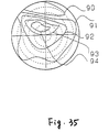
- FIG. 33 is an explanatory diagram of the optical characteristics of the liquid crystal device of the invention in the OFF condition.
- a comparison of FIG. 31 and FIG. 33 shows that FIG. 33 differs from FIG. 31 in that the optical anisotropic element made up of a liquid crystal macromolecular film is included as a principal component.
- the conditions for a principal component are the same as the example of a prior art STN liquid crystal device shown in FIG.
- the polarization states 75, 76 and 77 of each of the wavelengths after passing through the display cell 55 in FIG. 33 are exactly the same as 65, 66 and 67 in FIG. 31.
- the polarized light 75, 76 and 77 then passes through the optical anisotropic element 54.
- the optical anisotropic element 54 has an action that cancels wavelength dispersion caused by the polarized light 75, 76 and 77 passing through the display cell 55.
- passing the polarized light 75, 76 and 77 through the optical anisotropic element causes it to become linearly polarized light such as indicated by 78, 79 and 80, respectively, and then by passing it through a polarizing plate, it is emitted as linearly polarized light such as indicated by 81, 82, and 83, respectively.
- the spectra of the emitted light at this time are shown in FIG. 7.
- the coloration phenomenon in the OFF condition is cancelled in the liquid crystal device of the invention.
- numerous experimental results from embodiments described below and computer simulations confirm that there is no coloration under various conditions in the ON condition as well. The conditions at this time are
- the coloration phenomenon can be canceled as described above. Since improvement of these optical characteristics is the same as the optical compensation effect of the two-layer supertwist nematic liquid crystal cell disclosed in Japanese Laid-Open Patent Publication 3-18146, details are omitted here, but since the linearly polarized light that passes through one of the pair of polarizing plates passes through at least the display cell and the color compensation plate in the liquid crystal device of the invention obtained in this manner, the coloration caused by the birefringence and rotatory polarization of the STN display cell is canceled and light in the wavelength range 400 to 700 nm becomes elliptically polarized light nearly aligned in the direction of the major axis. Therefore, when it passes through the other polarizing plate, no particular wavelength range is blocked, thus resulting in the color of the light being nearly white after it has passed through the polarizing plate.
- a liquid crystal device can be offered at low cost that does not sacrifice the contrast, angle of visibility and other display characteristics of prior art two-layer supertwist nematic liquid crystal display devices and is compact and thin.
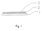
- FIG. 1 A schematic representation of a cross section of an example of the optical anisotropic element of the invention is shown in FIG. 1.
- a polyimide thin film 2 (SP740, Tore Co., Ltd.) is formed on a transparent substrate 1, and the polyimide thin film 2 on this substrate 1 is treated by rubbing in a uniaxial direction.
- This liquid crystal macromolecular film 3 has a twist orientation that is twisted 230 degrees to the right.
- the optical anisotropic element of the invention has an effect that compensates coloration caused by rotatory polarization and birefringence due to the twist of the liquid crystal in the STN liquid crystal cell, thus realizing a liquid crystal device with high contrast and high visibility.
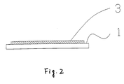
- FIG. 2 A schematic representation of a cross section of an example of the optical anisotropic element of the invention is shown in FIG. 2.
- the top of the transparent substrate 1 is treated by rubbing in a uniaxial direction.
- a liquid crystal macromolecular film 3 approximately 6 ⁇ m thick and produced by adding CB-15 (37), an optically active compound produced by Merck Corporation and having an asymmetrical center, to a concentration of 5% to a 95%:5% mixture of the side-chain liquid crystal macromolecules (3) and (2) shown above, which have a siloxane chain as a skeleton and demonstrate a nematic phase, is formed on this transparent substrate 1.
- This liquid crystal macromolecular film 3 has a twist orientation that is twisted 230 degrees to the right.
- the optical anisotropic element of the invention has an effect that compensates coloration caused by rotatory polarization and birefringence due to the twist of the liquid crystal in the STN liquid crystal cell, thus realizing a liquid crystal device with high contrast and high visibility.
- FIG. 3 A schematic representation of a cross section of an example of the optical anisotropic element of the invention is shown in FIG. 3.
- a polyimide thin film 2 (SP740, Tore Co., Ltd.) is formed on a transparent substrate 1, and the polyimide thin film 2 on this substrate 1 is treated by rubbing in a uniaxial direction.
- a protective film 4 with no optical anisotropy is formed on this liquid crystal macromolecular film 3.
- the optical anisotropic element of the invention has an effect that compensates coloration caused by rotatory polarization and birefringence due to the twist of the liquid crystal in the STN liquid crystal cell, thus realizing a liquid crystal device with high contrast and high visibility.
- FIG. 4 A schematic representation of a cross section of an example of the optical anisotropic element of the invention is shown in FIG. 4.
- the top of the transparent substrate 1 is treated by rubbing in a uniaxial direction.
- a liquid crystal macromolecular film 3 approximately 6 ⁇ m thick and produced by adding CB-15 (37), an optically active compound produced by Merck Corporation and having an asymmetrical center, to a concentration of 5% to a 95%:5% mixture of the side-chain liquid crystal macromolecules (3) and (2) shown above, which have a siloxane chain as a skeleton and demonstrate a nematic phase, is formed on this transparent substrate 1.
- a transparent protective film 4 with no optical anisotropy is formed on this liquid crystal macromolecular film 3.
- This liquid crystal macromolecular film 3 has a twist orientation that is twisted 230 degrees to the right.
- the optical anisotropic element of the invention has an effect that compensates coloration caused by rotatory polarization and birefringence due to the twist of the liquid crystal in the STN liquid crystal cell, thus realizing a liquid crystal device with high contrast and high visibility.
- FIG. 5 A schematic representation of a cross section of an example of the liquid crystal device of the invention equipped with the optical anisotropic element obtained in the first embodiment is shown in FIG. 5.
- the transparent substrates 5 of the liquid crystal cell having the transparent electrodes 51 and the liquid crystal orientation films 52 are mated together with the spacers 6 between them, and liquid crystal (ZLI4506, Merck Corporation) 7 is vacuum injected between them.
- This optical anisotropic element and liquid crystal cell are disposed between the two polarizing plates 8.
- the direction of orientation of the liquid crystal at this time, the direction of the absorption axes of the polarizing plates and the direction of the major axis of the liquid crystal macromolecules are shown in FIG. 6.
- FIG. 6 A schematic representation of a cross section of an example of the liquid crystal device of the invention equipped with the optical anisotropic element obtained in the first embodiment is shown in FIG. 5.
- 15 is the size of the twist angle of the liquid crystal display cell in FIG. 5
- 16 is the angle formed by direction 11 and direction 10
- 17 is the angle formed by 14 and direction 12
- 18 is the angle formed by direction 9 and direction 13
- 19 is the angle formed by direction 12 and direction 11.
- Angle 16 is 90 degrees and angle 17 is 45 degrees.
- the twist angle 15 of the liquid crystal display cell in FIG. 5 is approximately 200 degrees to the left, and ⁇ n x d of the liquid crystal in the liquid crystal display cell in FIG. 5 is 0.85 ⁇ m.
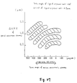
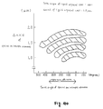
- FIG. 34 The relationship between contrast and angle of visibility is shown in FIG. 34.
- (D), (E) and (F) show the relationship between contrast and angle of visibility in a prior art two-layer supertwist nematic liquid crystal device, a liquid crystal device that uses one uniaxial oriented film, and a liquid crystal device that uses two uniaxial oriented films.
- the relationship between contrast and angle of visibility in a liquid crystal device equipped with an optical anisotropic element produced in this embodiment is shown in FIG. 35. As can be seen, a liquid crystal device is obtained in which the angle of visibility characteristic of the liquid crystal device is improved.
- FIG. 8 A schematic representation of a cross section of an example of a liquid crystal device that uses the optical anisotropic element of the second embodiment is shown in FIG. 8.
- the transparent substrates 5 of the liquid crystal cell having the transparent electrodes 51 and the liquid crystal orientation films 52 are mated together with the spacers 6 between them, and liquid crystal (ZLI4506, Merck Corporation) 7 is vacuum injected between them.
- This optical anisotropic element and liquid crystal display cell are disposed between the two polarizing plates 8.
- the configuration other than that described below is the same as the fifth embodiment, and therefore the above conditions are set as described below in this embodiment.
- Angle 16 is 85 degrees and angle 17 is 45 degrees.
- the twist angle 15 of the liquid crystal display cell is approximately 200 degrees to the left, and ⁇ n x d of the liquid crystal 7 in the liquid crystal display cell is 0.85 ⁇ m.
- FIG. 9 A schematic representation of a cross section of an example of a liquid crystal device that uses the optical anisotropic element of the third embodiment is shown in FIG. 9.
- the transparent substrates 5 of the liquid crystal cell having the transparent electrodes 51 and the liquid crystal orientation films 52 are mated together with the spacers 6 between them, and liquid crystal (ZLI4506, Merck Corporation) 7 is vacuum injected between them.
- This optical anisotropic element and liquid crystal display cell are disposed between the two polarizing plates 8.
- the direction of orientation of the liquid crystal, the direction of the absorption axis of the polarizing plates and the direction of the major axis of the liquid crystal macromolecules are the same as in the fifth embodiment.
- Angle 16 is 80 degrees and angle 17 is 50 degrees.
- the twist angle 15 of the liquid crystal display cell is approximately 230 degrees to the left, and ⁇ n x d of the liquid crystal 7 in the liquid crystal display cell is 0.85 ⁇ m.
- FIG. 10 A schematic representation of a cross section of an example of a liquid crystal device that uses the optical anisotropic element of the fourth embodiment is shown in FIG. 10.
- the transparent substrates 5 of the liquid crystal cell having the transparent electrodes 51 and the liquid crystal orientation films 52 are mated together with the spacers 6 between them, and liquid crystal (ZLI4506, Merck Corporation) 7 is vacuum injected between them.
- This optical anisotropic element and liquid crystal display cell are disposed between the two polarizing plates 8.
- the direction of orientation of the liquid crystal, the direction of the absorption axis of the polarizing plates and the direction of the major axis of the liquid crystal molecules are the same as in the fifth embodiment. The above conditions were set as described below in this embodiment.
- Angle 16 is 90 degrees and angle 17 is 45 degrees. Further, the twist angle 15 of the liquid crystal display cell is approximately 240 degrees to the left, and ⁇ n x d of the liquid crystal 7 in the liquid crystal display cell is 0.85 ⁇ m.
- assembly of the liquid crystal device is completed by connecting the driver for liquid crystal drive and the circuit for liquid crystal drive to the above liquid crystal cell and positioning a light source for illumination behind the liquid crystal cell. Black-and-white display in this liquid crystal device was confirmed by applying voltages equivalent to ON and OFF voltages, and display characteristics similar to those of the fifth embodiment were obtained.
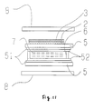
- FIG. 11 A schematic representation of a cross section of an example of the liquid crystal device of the invention is shown in FIG. 11.
- the transparent substrates 5 of the liquid crystal cell having the transparent electrodes 51 and the liquid crystal orientation films 52 are mated together with the spacers 6 between them, and liquid crystal (ZLI4506, Merck Corporation) 7 is vacuum injected between them.
- a polyimide thin film 2 (SP740, Tore Co., Ltd.) is formed on the transparent substrate 5 of the liquid crystal cell, which does not come in contact with the liquid crystal of the liquid crystal display cell, and the polyimide thin film 2 on this transparent substrate 5 is treated by rubbing in a uniaxial direction.
- This liquid crystal macromolecular film 3 has a twist orientation that is twisted 230 degrees to the right.
- This liquid crystal display cell equipped with an optical anisotropic element is disposed between the two polarizing plates 8.
- the direction of orientation of the liquid crystal, the direction of the absorption axis of the polarizing plates and the direction of the major axis of the liquid crystal molecules are the same as in the fifth embodiment.
- Angle 16 is 89 degrees and angle 17 is 45 degrees.
- the twist angle 15 of the liquid crystal display cell is approximately 200 degrees to the left, and ⁇ n x d of the liquid crystal 7 in the liquid crystal display cell is 0.85 ⁇ m.
- FIG. 12 A schematic representation of a cross section of an example of the liquid crystal device of the invention is shown in FIG. 12.
- the transparent substrates 5 of the liquid crystal cell having the transparent electrodes 51 and the liquid crystal orientation films 52 are mated together with the spacers 6 between them, and liquid crystal (ZLI4506, Merck Corporation) 7 is vacuum injected between them.
- the transparent substrate 5, which does not come in contact with the liquid crystal of the liquid crystal display cell, is treated by rubbing in a uniaxial direction.
- This liquid crystal macromolecular film 3 has a twist orientation that is twisted 230 degrees to the right.
- the liquid crystal display cell equipped with this optical anisotropic element is disposed between the two polarizing plates 8.
- the direction of orientation of the liquid crystal, the direction of the absorption axis of the polarizing plates and the direction of the major axis of the liquid crystal molecules are the same as in the fifth embodiment.
- Angle 16 is 85 degrees and angle 17 is 45 degrees.
- the twist angle 15 of the liquid crystal display cell is approximately 230 degrees to the left, and ⁇ n x d of the liquid crystal 7 in the liquid crystal display cell is 0.85 ⁇ m.
- FIG. 13 A schematic representation of a cross section of an example of the liquid crystal device of the invention is shown in FIG. 13.
- the transparent substrates 5 of the liquid crystal cell having the transparent electrodes 51 and the liquid crystal orientation films 52 are mated together with the spacers 6 between them, and liquid crystal (ZLI4506, Merck Corporation) 7 is vacuum injected between them.
- a polyimide thin film 2 (SP740, Tore Co., Ltd.) is formed on the transparent substrate 5 of the liquid crystal display cell, which does not come in contact with the liquid crystal of the liquid crystal display cell, and the polyimide thin film 2 on this transparent substrate 5 is treated by rubbing in a uniaxial direction.
- a protective film 4 with no optical anisotropy is formed on this liquid crystal macromolecular film 3.
- This liquid crystal macromolecular film 3 has a twist orientation that is twisted 230 degrees to the right.
- the liquid crystal display cell equipped with this optical anisotropic element is disposed between the two polarizing plates 8.
- the direction of orientation of the liquid crystal, the direction of the absorption axis of the polarizing plates and the direction of the major axis of the liquid crystal molecules are the same as in the fifth embodiment.
- Angle 16 is 100 degrees and angle 17 is 45 degrees.
- the twist angle 15 of the liquid crystal display cell is approximately 200 degrees to the left, and ⁇ n x d of the liquid crystal 7 in the liquid crystal display cell is 0.85 ⁇ m.
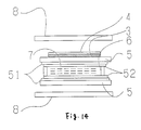
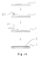
- Embodiment 12 A schematic representation of a cross section of an example of the liquid crystal device of the invention is shown in FIG. 14.
- the transparent substrates 5 of the liquid crystal cell having the transparent electrodes 51 and the liquid crystal orientation films 52 are mated together with the spacers 6 between them, and liquid crystal (ZLI4506, Merck Corporation) 7 is vacuum injected between them.
- the top of the transparent substrate 5 of the liquid crystal display cell, which does not come in contact with the liquid crystal 7 of the liquid crystal display cell, is treated by rubbing in a uniaxial direction.
- a liquid crystal macromolecular film 3 approximately 6 ⁇ m thick and produced by adding CB-15 (37), an optically active compound produced by Merck Corporation and having an asymmetrical center, to a concentration of 5% to a 90%:10% mixture of the side-chain liquid crystal macromolecules (3) and (2) shown above, which have a siloxane chain as a skeleton and demonstrate a nematic phase, is formed on the transparent substrate 5 of the liquid crystal display cell.
- a protective film 4 with no optical anisotropy is formed on this liquid crystal macromolecular film 3.
- This liquid crystal macromolecular film 3 has a twist orientation that is twisted 230 degrees to the right.
- the liquid crystal display cell equipped with this optical anisotropic element is disposed between the two polarizing plates 8.
- the direction of orientation of the liquid crystal, the direction of the absorption axis of the polarizing plates and the direction of the major axis of the liquid crystal molecules are the same as in the fifth embodiment.
- the above conditions were set as described below in this embodiment.
- Angle 16 is 90 degrees and angle 17 is 45 degrees.
- the twist angle 15 of the liquid crystal display cell is approximately 200 degrees to the left, and ⁇ n x d of the liquid crystal 7 in the liquid crystal display cell is 0.85 ⁇ m.
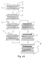
- Embodiment 14 An example of the production method of the optical anisotropic element of the first embodiment of the invention is shown in FIG. 15.
- a polyimide thin film 2 is formed by applying polyimide (SP740, Tore Co., Ltd.) on the transparent substrate 1 and heating the substrate to harden the film.
- the polyimide thin film 2 on this substrate is treated by rotational rubbing in one direction using a nylon brush 20, after which a liquid crystal macromolecular film 3 approximately 6 ⁇ m thick is formed by applying a liquid crystal macromolecular solution (18% solids concentration) prepared by adding CB-15 (37), an optically active compound produced by Merck Corporation and having an asymmetrical center, to a concentration of 5% to a 90%:10% mixture of the sidechain liquid crystal macromolecules (3) and (2) shown above, which have a siloxane chain as a skeleton and demonstrate a nematic phase, with a bar coater 21 and heating it to evaporate the solvent.
- a liquid crystal macromolecular solution (18% solids concentration) prepared by adding CB-15 (37), an optically active compound produced by Merck Corporation and having an asymmetrical center
- an optical anisotropic element with a twist orientation 230 degrees to the right is obtained by heating it for three hours at 80° C to perform orientation and then quickly cooling it.
- the liquid crystal macromolecules are uniformly oriented over a wide range.
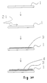
- FIG. 16 An example of the production method of the optical anisotropic element of the second embodiment of the invention is shown in FIG. 16.
- the top of this substrate 1 is treated by rotational rubbing in one direction using a nylon brush 20, after which a liquid crystal macromolecular film 3 approximately 6 ⁇ m thick is formed by applying a liquid crystal macromolecular solution (18% solids concentration) prepared by adding CB-15 (37), an optically active compound produced by Merck Corporation and having an asymmetrical center, to a concentration of 5% to a 90%:10% mixture of the side-chain liquid crystal macromolecules (3) and (2) shown above, which have a siloxane chain as a skeleton and demonstrate a nematic phase, with a bar coater 21 and heating it to evaporate the solvent.
- a liquid crystal macromolecular solution (18% solids concentration) prepared by adding CB-15 (37), an optically active compound produced by Merck Corporation and having an asymmetrical center
- an optical anisotropic element with a twist orientation 230 degrees to the right is obtained by heating it for three hours at 80° C to perform orientation and then quickly cooling it.
- the liquid crystal macromolecules are uniformly oriented over a wide range.
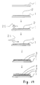
- FIG. 17 An example of the production method of the optical anisotropic element of the third embodiment of the invention is shown in FIG. 17.
- a polyimide thin film 2 is formed by applying polyimide (SP740, Tore Co., Ltd.) on the transparent substrate 1 and heating the substrate to harden the film.
- the polyimide thin film 2 on this substrate is treated by rotational rubbing in one direction using a nylon brush 20, after which a liquid crystal macromolecular film 3 approximately 6 ⁇ m thick is formed by applying a liquid crystal macromolecular solution (18% solids concentration) prepared by adding CB-15 (37), an optically active compound produced by Merck Corporation and having an asymmetrical center, to a concentration of 5% to a 90%:10% mixture of the side-chain liquid crystal macromolecules (3) and (2) shown above, which have a siloxane chain as a skeleton and demonstrate a nematic phase, with a bar coater 21 and heating it to evaporate the solvent.
- a liquid crystal macromolecular solution (18% solids concentration) prepared by adding CB-15 (37), an optically active compound produced by Merck Corporation and having an asymmetrical center
- an optical anisotropic element with a twist orientation 230 degrees to the right is obtained by heating it for three hours at 80° C to perform orientation and then quickly cooling it.
- a water-based acrylic resin is then applied to form a protective film 4.
- the liquid crystal macromolecules are uniformly oriented over a wide range.
- FIG. 18 An example of the production method of the optical anisotropic element of the fourth embodiment of the invention is shown in FIG. 18.
- the top of this transparent substrate 1 is treated by rotational rubbing in one direction using a nylon brush 20, after which a liquid crystal macromolecular film 3 approximately 6 ⁇ m thick is formed by applying a liquid crystal macromolecular solution (18% solids concentration) prepared by adding CB-15 (37), an optically active compound produced by Merck Corporation and having an asymmetrical center, to a concentration of 5% to a 90%:10% mixture of the side-chain liquid crystal macromolecules (3) and (2) shown above, which have a siloxane chain as a skeleton and demonstrate a nematic phase, with a bar coater 21 and heating it to evaporate the solvent.
- a liquid crystal macromolecular solution (18% solids concentration) prepared by adding CB-15 (37), an optically active compound produced by Merck Corporation and having an asymmetrical center
- an optical anisotropic element with a twist orientation 230 degrees to the right is obtained by heating it for three hours at 80° C to perform orientation and then quickly cooling it.
- a water-based acrylic resin is then applied to form a protective film 4.
- the liquid crystal macromolecules are uniformly oriented over a wide range.
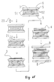
- FIG. 19 An example of the production method of the optical anisotropic element of the invention is shown in FIG. 19.
- a plastic substrate produced by drawing was used as the transparent substrate in this embodiment.
- a liquid crystal macromolecular film 3 approximately 6 ⁇ m thick is formed on the top of the transparent substrate 1 by applying a liquid crystal macromolecular solution (18% solids concentration) prepared by adding CB-15 (37), an optically active compound produced by Merck Corporation and having an asymmetrical center, to a concentration of 5% to a 90%:10% mixture of the side-chain liquid crystal macromolecules (3) and (2) shown above, which have a siloxane chain as a skeleton and demonstrate a nematic phase, with a bar coater 21 and heating it to evaporate the solvent.
- a liquid crystal macromolecular solution (18% solids concentration) prepared by adding CB-15 (37), an optically active compound produced by Merck Corporation and having an asymmetrical center
- an optical anisotropic element with a twist orientation 230 degrees to the right is obtained by heating it for three hours at 80° C to perform orientation and then quickly cooling it.
- the liquid crystal macromolecules are uniformly oriented over a wide range.
- FIG. 20 An example of the production method of the optical anisotropic element of the invention is shown in FIG. 20.
- a plastic substrate produced by drawing was used as the transparent substrate in this embodiment.
- a liquid crystal macromolecular film 3 approximately 6 ⁇ m thick is formed on the top of this transparent substrate 1 by applying a liquid crystal macromolecular solution (18% solids concentration) prepared by adding CB-15 (37), an optically active compound produced by Merck Corporation and having an asymmetrical center, to a concentration of 5% to a 90%:10% mixture of the side-chain liquid crystal macromolecules (3) and (2) shown above, which have a siloxane chain as a skeleton and demonstrate a nematic phase, with a bar coater 21 and heating it to evaporate the solvent.
- a liquid crystal macromolecular solution (18% solids concentration) prepared by adding CB-15 (37), an optically active compound produced by Merck Corporation and having an asymmetrical center
- an optical anisotropic element with a twist orientation 230 degrees to the right is obtained by heating it for three hours at 80° C to perform orientation and then quickly cooling it.
- the liquid crystal macromolecules are uniformly oriented over a wide range.
- Twentieth embodiment The same effect is obtained in the liquid crystal devices of the eighteenth and nineteenth embodiments when a drawn mixture of a material with a negative optical anisotropy and a material with a positive optical anisotropy is used for the drawn plastic substrate.
- Twenty-first embodiment The same effect is obtained in the liquid crystal devices of the eighteenth and nineteenth embodiments when a film that is a lamination of a material with a negative optical anisotropy and a material with a positive optical anisotropy is used for the drawn plastic substrate.
- Twenty-second embodiment The same effect is obtained in the liquid crystal devices of the eighteenth and nineteenth embodiments when a film on which a drawn film with optical anisotropy is superposed such that the axes of drawing intersect each other at right angles.
- Twenty-third embodiment The same effect is obtained in the liquid crystal devices of the fourteenth, fifteenth, sixteenth and seventeenth embodiments when inorganic glass is used for the transparent substrate.
- Twenty-fourth embodiment The same effect is obtained in the liquid crystal devices of the fourteenth, fifteenth, sixteenth and seventeenth embodiments when a plastic substrate obtained by casting is used for the transparent substrate.
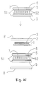
- Twenty-fifth embodiment A schematic representation of an example of the production method for a liquid crystal device equipped with the optical anisotropic element of the invention is shown in FIG. 21.
- a transparent electrode 51 1000 ⁇ thick and made from ITO is formed on the transparent substrate 5 of the liquid crystal display cell, and after it has been patterned as prescribed by a photo process, the liquid crystal orientation film 52 is formed to prepare the transparent substrate 5 of the liquid crystal display cell with a transparent electrode 51 and liquid crystal orientation film 52.
- the liquid crystal orientation film 52 is formed, and the cell is assembled so that the electrodes are at nearly right angles to each other.
- the liquid crystal device is prepared by positioning the optical anisotropic element produced in the fourteenth embodiment on the liquid crystal display cell and sandwiching everything between two polarizing plates 8.
- the direction of orientation of the liquid crystal, the direction of the absorption axis of the polarizing plates and the direction of the major axis of the liquid crystal macromolecules are the same as in the fifth embodiment.
- Twenty-sixth embodiment The same display characteristics as in the twenty-fifth embodiment can be obtained when the optical anisotropic element produced in the fifteenth embodiment is combined with the liquid crystal display cell in the same way as in the twenty-fifth embodiment.
- Twenty-seventh embodiment The same display characteristics as in the twenty-fifth embodiment can be obtained when the optical anisotropic element produced in the sixteenth embodiment is combined with the liquid crystal display cell in the same way as in the twenty-fifth embodiment.
- Twenty-eighth embodiment The same display characteristics as in the twenty-fifth embodiment can be obtained when the optical anisotropic element produced in the seventeenth embodiment is combined with the liquid crystal display cell in the same way as in the twenty-fifth embodiment.
- Twenty-ninth embodiment The same display characteristics as in the twenty-fifth embodiment can be obtained when the optical anisotropic element produced in the eighteenth embodiment is combined with the liquid crystal display cell in the same way as in the twenty-fifth embodiment.
- Thirtieth embodiment The same display characteristics as in the twenty-fifth embodiment can be obtained when the optical anisotropic element produced in the nineteenth embodiment is combined with the liquid crystal display cell in the same way as in the twenty-fifth embodiment.
- FIG. 22 A schematic representation of an example of the production method for a liquid crystal device equipped with the optical anisotropic element of the invention is shown in FIG. 22.
- a transparent electrode 51 1,000 ⁇ thick and made from ITO is formed on the transparent substrate 5 of the liquid crystal display cell, and after it has been patterned as prescribed by a photo process, the liquid crystal orientation film 52 is formed to prepare the transparent substrate 5 of the liquid crystal display cell with a transparent electrode 51 and liquid crystal orientation film 52.
- a polyimide thin film 2 is formed by applying polyimide (SP740, Tore Co., Ltd.) on the transparent substrate 5 of the liquid crystal display cell, which does not come in contact with the liquid crystal 7 of the liquid crystal display cell, and heating the substrate to harden the film.
- the polyimide thin film 2 on this substrate is treated by rotational rubbing in one direction using a nylon brush 20, after which a liquid crystal macromolecular film 3 approximately 6 ⁇ m thick is formed by applying a liquid crystal macromolecular solution (18% solids concentration) prepared by adding CB-15 (37), an optically active compound produced by Merck Corporation and having an asymmetrical center, to a concentration of 5% to a 90%:10% mixture of the side-chain liquid crystal macromolecules (3) and (2) shown above, which have a siloxane chain as a skeleton and demonstrate a nematic phase, with a bar coater 21 and heating it to evaporate the solvent.
- a liquid crystal macromolecular solution (18% solids concentration) prepared by adding CB-15 (37), an optically active compound produced by Merck Corporation and having an asymmetrical center
- a liquid crystal device equipped with an optical anisotropic element with a twist orientation 230 degrees to the right is obtained by heating the element for three hours at 80° C to perform orientation and then quickly cooling it.
- Each of the axes is disposed in the same manner as in the ninth embodiment.
- assembly of the liquid crystal device is completed by connecting the driver for liquid crystal drive and the circuit for liquid crystal drive to the above liquid crystal device and positioning a light source for illumination behind the liquid crystal device.
- Black-and-white display in this liquid crystal device was confirmed by applying voltages equivalent to ON and OFF voltages, and the same display characteristics as in the fifth embodiment were obtained.
- FIG. 23 A schematic representation of an example of the production method for a liquid crystal device equipped with the optical anisotropic element of the invention is shown in FIG. 23.
- a transparent electrode 51 1,000 ⁇ thick and made from ITO is formed on the transparent substrate 5 of the liquid crystal display cell, and after it has been patterned as prescribed by a photo process, the liquid crystal orientation film 52 is formed to prepare the transparent substrate 5 of the liquid crystal display cell with a transparent electrode 51 and liquid crystal orientation film 52.
- the liquid crystal orientation film 52 is formed, and the cell is assembled so that the electrodes are at nearly right angles to each other.
- the top of the transparent substrate 5 of the liquid crystal display cell which does not come in contact with the liquid crystal 7 of the liquid crystal display cell, is treated by rotational rubbing in one direction using a nylon brush 20, after which a liquid crystal macromolecular film 3 approximately 6 ⁇ m thick is formed by applying a liquid crystal macromolecular solution (18% solids concentration) prepared by adding CB-15 (37), an optically active compound produced by Merck Corporation and having an asymmetrical center, to a concentration of 5% to a 90%:10% mixture of the side-chain liquid crystal macromolecules (3) and (2) shown above, which have a siloxane chain as a skeleton and demonstrate a nematic phase, with a bar coater 21 and heating it to evaporate the solvent.
- a liquid crystal macromolecular solution (18% solids concentration) prepared by adding CB-15 (37), an optically active compound produced by Merck Corporation and having an asymmetrical center
- a liquid crystal device equipped with an optical anisotropic element with a twist orientation 230 degrees to the right is obtained by heating the element for three hours at 80° C to perform orientation and then quickly cooling it.
- the liquid crystal macromolecules are uniformly oriented over a wide range.
- Each of the axes is disposed in the same manner as in the tenth embodiment.
- assembly of the liquid crystal device is completed by connecting the driver for liquid crystal drive and the circuit for liquid crystal drive to the above liquid crystal device and positioning a light source for illumination behind the liquid crystal device. Black-and-white display in this liquid crystal device was confirmed by applying voltages equivalent to ON and OFF voltages. Those contrast curves are shown in FIG. 7. This embodiment yielded a liquid crystal device with the same relationship between contrast and angle of visibility as that shown in FIG. 35.
- FIG. 24 A schematic representation of an example of the production method for a liquid crystal device equipped with the optical anisotropic element of the invention is shown in FIG. 24.
- a transparent electrode 51 1,000 ⁇ thick and made from ITO is formed on the transparent substrate 5 of the liquid crystal display cell, and after it has been patterned as prescribed by a photo process, the liquid crystal orientation film 52 is formed to prepare the transparent substrate 5 of the liquid crystal display cell with a transparent electrode 51 and liquid crystal orientation film 52.
- a polyimide thin film 2 is formed by applying polyimide (SP740, Tore Co., Ltd.) on the transparent substrate 5 of the liquid crystal display cell, which does not come in contact with the liquid crystal 7 of the liquid crystal display cell, and heating the substrate to harden the film.
- the polyimide thin film 2 on this substrate is treated by rotational rubbing in one direction using a nylon brush 20, after which a liquid crystal macromolecular film 3 approximately 6 ⁇ m thick is formed by applying a liquid crystal macromolecular solution (18% solids concentration) prepared by adding CB-15 (37), an optically active compound produced by Merck Corporation and having an asymmetrical center, to a concentration of 5% to a 90%:10% mixture of the side-chain liquid crystal macromolecules (3) and (2) shown above, which have a siloxane chain as a skeleton and demonstrate a nematic phase, with a bar coater 21 and heating it to evaporate the solvent.
- a liquid crystal macromolecular solution (18% solids concentration) prepared by adding CB-15 (37), an optically active compound produced by Merck Corporation and having an asymmetrical center
- a liquid crystal device equipped with an optical anisotropic element with a twist orientation 230 degrees to the right is obtained by heating the element for three hours at 80° C to perform orientation and then quickly cooling it.
- a protective film 4 is formed by applying a water-based acrylic resin.
- Each of the axes is disposed in the same manner as in the eleventh embodiment.
- assembly of the liquid crystal device is completed by connecting the driver for liquid crystal drive and the circuit for liquid crystal drive to the above liquid crystal device and positioning a light source for illumination behind the liquid crystal device. Black-and-white display in this liquid crystal device was confirmed by applying voltages equivalent to ON and OFF voltages. This embodiment yielded a liquid crystal device with the same relationship between contrast and angle of visibility as that shown in FIG. 35.
- FIG. 25 A schematic representation of an example of the production method for a liquid crystal device equipped with the optical anisotropic element of the invention is shown in FIG. 25.
- a transparent electrode 51 1,000 ⁇ thick and made from ITO is formed on the transparent substrate 5 of the liquid crystal display cell, and after it has been patterned as prescribed by a photo process, the liquid crystal orientation film 52 is formed to prepare the transparent substrate 5 of the liquid crystal display cell with a transparent electrode 51 and liquid crystal orientation film 52.
- the liquid crystal orientation film 52 is formed, and the cell is assembled so that the electrodes are at nearly right angles to each other.
- the top of the transparent substrate 5 of the liquid crystal display cell which does not come in contact with the liquid crystal 7 of the liquid crystal display cell, is treated by rotational rubbing in one direction using a nylon brush 20, after which a liquid crystal macromolecular film 3 approximately 6 ⁇ m thick is formed by applying a liquid crystal macromolecular solution (18% solids concentration) prepared by adding CB-15 (37), an optically active compound produced by Merck Corporation and having an asymmetrical center, to a concentration of 5% to a 90%:10% mixture of the side-chain liquid crystal macromolecules (3) and (2) shown above, which have a siloxane chain as a skeleton and demonstrate a nematic phase, with a bar coater 21 and heating it to evaporate the solvent.
- a liquid crystal macromolecular solution (18% solids concentration) prepared by adding CB-15 (37), an optically active compound produced by Merck Corporation and having an asymmetrical center
- a liquid crystal device equipped with an optical anisotropic element with a twist orientation 230 degrees to the right is obtained by heating the element for three hours at 80° C to perform orientation and then quickly cooling it.
- a protective film 4 is formed by applying a water-based acrylic resin.
- the liquid crystal macromolecules are uniformly oriented over a wide range. Each of the axes is disposed in the same manner as in the twelfth embodiment.
- assembly of the liquid crystal device is completed by connecting the driver for liquid crystal drive and the circuit for liquid crystal drive to the above liquid crystal device and positioning a light source for illumination behind the liquid crystal device. Black-and-white display in this liquid crystal device was confirmed by applying voltages equivalent to ON and OFF voltages. This embodiment yielded a liquid crystal device with the same relationship between contrast and angle of visibility as that shown in FIG. 35.
- FIG. 26 A schematic representation of an example of the production method for a liquid crystal device equipped with the optical anisotropic element of the invention is shown in FIG. 26.
- a transparent electrode 51 1,000 ⁇ thick and made from ITO is formed on the transparent substrate 5 of the liquid crystal display cell, and after it has been patterned as prescribed by a photo process, the liquid crystal orientation film 52 is formed to prepare the transparent substrate 5 of the liquid crystal display cell with a transparent electrode 51 and liquid crystal orientation film 52.
- a polyimide thin film 2 is formed by applying polyimide (SP740, Tore Co., Ltd.) on the transparent substrate 5 of the liquid crystal display cell, which does not come in contact with the liquid crystal 7 of the liquid crystal display cell, and heating the substrate to harden the film.
- the polyimide thin film 2 on this substrate is treated by rotational rubbing in one direction using a nylon brush 20, after which a liquid crystal macromolecular film 3 approximately 6 ⁇ m thick is formed by applying a liquid crystal macromolecular solution (18% solids concentration) prepared by adding CB-15 (37), an optically active compound produced by Merck Corporation and having an asymmetrical center, to a concentration of 5% to a 90%:10% mixture of the side-chain liquid crystal macromolecules (3) and (2) shown above, which have a siloxane chain as a skeleton and demonstrate a nematic phase, with a bar coater 21 and heating it to evaporate the solvent.
- a liquid crystal macromolecular solution (18% solids concentration) prepared by adding CB-15 (37), an optically active compound produced by Merck Corporation and having an asymmetrical center
- a liquid crystal device equipped with an optical anisotropic element with a twist orientation 230 degrees to the right is obtained by heating the element for three hours at 80° C to perform orientation and then quickly cooling it.
- Each of the axes is disposed in the same manner as in the ninth embodiment.
- assembly of the liquid crystal device is completed by connecting the driver for liquid crystal drive and the circuit for liquid crystal drive to the above liquid crystal device and positioning a light source for illumination behind the liquid crystal device. Black-and-white display in this liquid crystal device was confirmed by applying voltages equivalent to ON and OFF voltages. This embodiment yielded a liquid crystal device with the same relationship between contrast and angle of visibility as that shown in FIG. 35.
- FIG. 27 A schematic representation of an example of the production method for a liquid crystal device equipped with the optical anisotropic element of the invention is shown in FIG. 27.
- a transparent electrode 51 1,000 ⁇ thick and made from ITO is formed on the transparent substrate 5 of the liquid crystal display cell, and after it has been patterned as prescribed by a photo process, the liquid crystal orientation film 52 is formed to prepare the transparent substrate 5 of the liquid crystal display cell with a transparent electrode 51 and liquid crystal orientation film 52.
- the liquid crystal orientation film 52 is formed, and the cell is assembled so that the electrodes are at nearly right angles to each other.
- the top of the transparent substrate 5 of the liquid crystal display cell which does not come in contact with the liquid crystal 7 of the liquid crystal display cell, is treated by rotational rubbing in one direction using a nylon brush 20, after which a liquid crystal macromolecular film 3 approximately 6 ⁇ m thick is formed by applying a liquid crystal macromolecular solution (18% solids concentration) prepared by adding CB-15 (37), an optically active compound produced by Merck Corporation and having an asymmetrical center, to a concentration of 5% to a 90%:10% mixture of the side-chain liquid crystal macromolecules (3) and (2) shown above, which have a siloxane chain as a skeleton and demonstrate a nematic phase, with a bar coater 21 and heating it to evaporate the solvent.
- a liquid crystal macromolecular solution (18% solids concentration) prepared by adding CB-15 (37), an optically active compound produced by Merck Corporation and having an asymmetrical center
- a liquid crystal device equipped with an optical anisotropic element with a twist orientation 230 degrees to the right is obtained by heating the element for three hours at 80° C to perform orientation and then quickly cooling it.
- Each of the axes is disposed in the same manner as in the ninth embodiment.
- assembly of the liquid crystal device is completed by connecting the driver for liquid crystal drive and the circuit for liquid crystal drive to the above liquid crystal device and positioning a light source for illumination behind the liquid crystal device. Black-and-white display in this liquid crystal device was confirmed by applying voltages equivalent to ON and OFF voltages. This embodiment yielded a liquid crystal device with the same relationship between contrast and angle of visibility as that shown in FIG. 35.
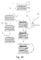
- FIG. 28 A schematic representation of an example of the production method for a liquid crystal device equipped with the optical anisotropic element of the invention is shown in FIG. 28.
- a transparent electrode 51 1,000 ⁇ thick and made from ITO is formed on the transparent substrate 5 of the liquid crystal display cell, and after it has been patterned as prescribed by a photo process, a polyimide thin film 2 is formed on the surface of the transparent substrate 5 of the liquid crystal display cell on which the transparent electrode 51 is not formed, and it is rubbed with a nylon brush.
- a liquid crystal macromolecular film 3 approximately 6 ⁇ m thick is formed by applying a liquid crystal macromolecular solution (18% solids concentration) prepared by adding CB-15 (37), an optically active compound produced by Merck Corporation and having an asymmetrical center, to a concentration of 5% to a 90%:10% mixture of the side-chain liquid crystal macromolecules (3) and (2) shown above, which have a siloxane chain as a skeleton and demonstrate a nematic phase, with a bar coater 21 and heating it to evaporate the solvent.
- a liquid crystal macromolecular solution (18% solids concentration) prepared by adding CB-15 (37), an optically active compound produced by Merck Corporation and having an asymmetrical center
- the transparent substrate 5 of the liquid crystal display cell which is equipped with an optical anisotropic element having a twist orientation 230 degrees to the right and produced by heating the element for three hours at 80° C to perform orientation and then quickly cooling it, is obtained. Further, a plastic substrate 120 ⁇ m thick is formed as a protective film 4. Next, a liquid crystal orientation film 52 is formed on the surface of the transparent substrate 5 of the liquid crystal display cell equipped with this optical anisotropic element on which the optical anisotropic element is not formed.
- a transparent electrode 51 is patterned and a liquid crystal orientation film formed in a similar manner on the opposing transparent substrate 5 of the liquid crystal display cell, which is separated by spacers 6 and liquid crystal (ZLI4506, Merck Corporation), and the cell is assembled so that the electrodes are at nearly right angles to each other.
- Each of the axes is disposed in the same manner as in the ninth embodiment.
- assembly of the liquid crystal device is completed by connecting the driver for liquid crystal drive and the circuit for liquid crystal drive to the above liquid crystal device and positioning a light source for illumination behind the liquid crystal device. Black-and-white display in this liquid crystal device was confirmed by applying voltages equivalent to ON and OFF voltages. This embodiment yielded a liquid crystal device with the same relationship between contrast and angle of visibility as that shown in FIG. 35.
- FIG. 29 A schematic representation of an example of the production method for a liquid crystal device equipped with the optical anisotropic element of the invention is shown in FIG. 29.
- a transparent electrode 51 1,000 ⁇ thick and made from ITO is formed on the transparent substrate 5 of the liquid crystal display cell, and after it has been patterned as prescribed by a photo process, a polyimide thin film 2 is formed on the surface of the transparent substrate 5 of the liquid crystal display cell on which the transparent electrode 51 is not formed, and it is rubbed with a nylon brush.
- a liquid crystal macromolecular film 3 approximately 6 ⁇ m thick is formed by applying a liquid crystal macromolecular solution (18% solids concentration) prepared by adding CB-15 (37), an optically active compound produced by Merck Corporation and having an asymmetrical center, to a concentration of 5% to a 90%:10% mixture of the side-chain liquid crystal macromolecules (3) and (2) shown above, which have a siloxane chain as a skeleton and demonstrate a nematic phase, with a bar coater 21 and heating it to evaporate the solvent.
- a liquid crystal macromolecular solution (18% solids concentration) prepared by adding CB-15 (37), an optically active compound produced by Merck Corporation and having an asymmetrical center
- the transparent substrate 5 of the liquid crystal display cell which is equipped with an optical anisotropic element having a twist orientation 230 degrees to the right and produced by heating the element for three hours at 80° C to perform orientation and then quickly cooling it, is obtained. Further, a protective film 4 is formed by applying a water-based acrylic resin. Next, a liquid crystal orientation film 52 is formed on the surface of the transparent substrate 5 of the liquid crystal display cell equipped with this optical anisotropic element on which the optical anisotropic element is not formed.
- a transparent electrode 51 is patterned and a liquid crystal orientation film formed in a similar manner on the opposing transparent substrate 5 of the liquid crystal display cell, which is separated by spacers 6 and liquid crystal (ZLI4506, Merck Corporation), and the cell is assembled so that the electrodes are at nearly right angles to each other.
- Each of the axes is disposed in the same manner as in the ninth embodiment.
- assembly of the liquid crystal device is completed by connecting the driver for liquid crystal drive and the circuit for liquid crystal drive to the above liquid crystal device and positioning a light source for illumination behind the liquid crystal device. Black-and-white display in this liquid crystal device was confirmed by applying voltages equivalent to ON and OFF voltages. This embodiment yielded a liquid crystal device with the same relationship between contrast and angle of visibility as that shown in FIG. 35.
- Forty-second embodiment The same effect can be obtained in the embodiments of the invention when a macromolecular material with viscosity is used as the protective film.
- liquid crystal devices with superior display performance be produced at low cost, but it also facilitates the supply of liquid crystal displays, light modulating elements, liquid crystal televisions and liquid crystal shutters that accommodate the trend toward greater compactness and lighter weight.
Landscapes
- Chemical & Material Sciences (AREA)
- Crystallography & Structural Chemistry (AREA)
- Physics & Mathematics (AREA)
- Engineering & Computer Science (AREA)
- Materials Engineering (AREA)
- Organic Chemistry (AREA)
- Nonlinear Science (AREA)
- Spectroscopy & Molecular Physics (AREA)
- Mathematical Physics (AREA)
- General Physics & Mathematics (AREA)
- Optics & Photonics (AREA)
- Liquid Crystal (AREA)
- Polarising Elements (AREA)
Applications Claiming Priority (18)
| Application Number | Priority Date | Filing Date | Title |
|---|---|---|---|
| JP1327091 | 1991-02-04 | ||
| JP13269/91 | 1991-02-04 | ||
| JP13270/91 | 1991-02-04 | ||
| JP1326991 | 1991-02-04 | ||
| JP2725091 | 1991-02-21 | ||
| JP27250/91 | 1991-02-21 | ||
| JP8838091 | 1991-04-19 | ||
| JP88380/91 | 1991-04-19 | ||
| JP167970/91 | 1991-07-09 | ||
| JP16797091 | 1991-07-09 | ||
| JP16797191 | 1991-07-09 | ||
| JP167971/91 | 1991-07-09 | ||
| JP341341/91 | 1991-12-24 | ||
| JP34134191 | 1991-12-24 | ||
| JP5943/92 | 1992-01-16 | ||
| JP594392 | 1992-01-16 | ||
| JP953692 | 1992-01-22 | ||
| JP9536/92 | 1992-01-22 |
Publications (2)
| Publication Number | Publication Date |
|---|---|
| EP0527231A1 true EP0527231A1 (de) | 1993-02-17 |
| EP0527231A4 EP0527231A4 (en) | 1993-04-28 |
Family
ID=27576516
Family Applications (1)
| Application Number | Title | Priority Date | Filing Date |
|---|---|---|---|
| EP19920904229 Withdrawn EP0527231A4 (en) | 1991-02-04 | 1992-01-31 | Optical anisotropic material and its manufacturing, and liquid crystal device provided therewith and its manufacturing |
Country Status (3)
| Country | Link |
|---|---|
| EP (1) | EP0527231A4 (de) |
| KR (1) | KR100250693B1 (de) |
| WO (1) | WO1992014180A1 (de) |
Cited By (9)
| Publication number | Priority date | Publication date | Assignee | Title |
|---|---|---|---|---|
| GB2272779A (en) * | 1992-11-18 | 1994-05-25 | Fuji Photo Film Co Ltd | Optically anisotropic element |
| EP0617111A1 (de) * | 1993-03-25 | 1994-09-28 | Sumitomo Chemical Company, Limited | Optisch Anisotropisches Material, Verfahren zur Herstellung, Verzögerungsplatte und flüssigkristalle Anzeige, die es verwenden |
| EP0678567A1 (de) * | 1994-04-22 | 1995-10-25 | Sumitomo Chemical Company, Limited | Verzögerungsfilm und dessen Herstellung |
| EP0704514A3 (de) * | 1994-09-26 | 1996-05-01 | Sumitomo Chemical Co | |
| EP0712013A3 (de) * | 1994-11-10 | 1997-03-19 | Sumitomo Chemical Co | Optisch anisotropischer Film |
| GB2305925A (en) * | 1995-10-06 | 1997-04-23 | Merck Patent Gmbh | Anisotropic polymer |
| US5863457A (en) * | 1993-12-24 | 1999-01-26 | Dainippon Ink And Chemicals, Inc. | Polymerizable liquid crystal composition and optically anisotropic film comprising the same |
| US6294231B1 (en) | 1998-09-17 | 2001-09-25 | Sumitomo Chemical Company, Limited | Optically anisotropic film, method of manufacturing the same, and liquid crystal display apparatus |
| EP1026541A4 (de) * | 1998-08-25 | 2002-02-06 | Citizen Watch Co Ltd | Flüssigkristallanzeige und deren herstellungsverfahren |
Families Citing this family (1)
| Publication number | Priority date | Publication date | Assignee | Title |
|---|---|---|---|---|
| JP6171276B2 (ja) * | 2011-07-12 | 2017-08-02 | 住友化学株式会社 | 偏光子及びその製造方法 |
Family Cites Families (6)
| Publication number | Priority date | Publication date | Assignee | Title |
|---|---|---|---|---|
| JPS64519A (en) * | 1986-05-19 | 1989-01-05 | Seiko Epson Corp | Liquid crystal display device |
| JPH0796575B2 (ja) * | 1987-08-28 | 1995-10-18 | 汪芳 白井 | 高分子液晶材料 |
| JPH01222220A (ja) * | 1988-03-01 | 1989-09-05 | Matsushita Electric Ind Co Ltd | 光学補償用有機フィルムとその製造方法 |
| JPH01234414A (ja) * | 1988-03-14 | 1989-09-19 | Idemitsu Kosan Co Ltd | 液晶性架橋ポリマー |
| JPH0267393A (ja) * | 1988-08-31 | 1990-03-07 | Ricoh Co Ltd | 液晶素子 |
| DE3925382A1 (de) * | 1989-06-14 | 1991-01-03 | Merck Patent Gmbh | Elektrooptisches system mit kompensationsfilm |
-
1992
- 1992-01-31 WO PCT/JP1992/000097 patent/WO1992014180A1/ja not_active Ceased
- 1992-01-31 EP EP19920904229 patent/EP0527231A4/en not_active Withdrawn
- 1992-09-24 KR KR1019920702316A patent/KR100250693B1/ko not_active Expired - Fee Related
Cited By (18)
| Publication number | Priority date | Publication date | Assignee | Title |
|---|---|---|---|---|
| GB2272779B (en) * | 1992-11-18 | 1996-12-18 | Fuji Photo Film Co Ltd | Optically anisotropic element and method for manufacturing the same |
| GB2272779A (en) * | 1992-11-18 | 1994-05-25 | Fuji Photo Film Co Ltd | Optically anisotropic element |
| US5688436A (en) * | 1993-03-25 | 1997-11-18 | Sumitomo Chemical Company, Limited | Optically anisotropic material, process for producing it, and retardation plate and liquid crystal display device using same |
| SG85050A1 (en) * | 1993-03-25 | 2001-12-19 | Sumitomo Chemical Co | Optically anisotropic material, process for producing it, and retardation plate and liquid crystal display device using same |
| EP0617111A1 (de) * | 1993-03-25 | 1994-09-28 | Sumitomo Chemical Company, Limited | Optisch Anisotropisches Material, Verfahren zur Herstellung, Verzögerungsplatte und flüssigkristalle Anzeige, die es verwenden |
| US5693253A (en) * | 1993-03-25 | 1997-12-02 | Sumitomo Chemical Company, Limited | Optically anisotropic material, process for producing it, and retardation plate and liquid crystal device using same |
| US5863457A (en) * | 1993-12-24 | 1999-01-26 | Dainippon Ink And Chemicals, Inc. | Polymerizable liquid crystal composition and optically anisotropic film comprising the same |
| EP0678567A1 (de) * | 1994-04-22 | 1995-10-25 | Sumitomo Chemical Company, Limited | Verzögerungsfilm und dessen Herstellung |
| US5601884A (en) * | 1994-04-22 | 1997-02-11 | Sumitomo Chemical Company, Limited | Retardation film and production thereof |
| EP0704514A3 (de) * | 1994-09-26 | 1996-05-01 | Sumitomo Chemical Co | |
| US5730899A (en) * | 1994-09-26 | 1998-03-24 | Sumitomo Chemical Company, Limited | Optically anisotropic film |
| EP0712013A3 (de) * | 1994-11-10 | 1997-03-19 | Sumitomo Chemical Co | Optisch anisotropischer Film |
| EP1329748A3 (de) * | 1994-11-10 | 2005-02-02 | Sumitomo Chemical Company, Limited | Optisch anisotropischer Film |
| GB2305925B (en) * | 1995-10-06 | 1999-10-13 | Merck Patent Gmbh | Anistropic polymer |
| GB2305925A (en) * | 1995-10-06 | 1997-04-23 | Merck Patent Gmbh | Anisotropic polymer |
| EP1026541A4 (de) * | 1998-08-25 | 2002-02-06 | Citizen Watch Co Ltd | Flüssigkristallanzeige und deren herstellungsverfahren |
| US6853437B1 (en) | 1998-08-25 | 2005-02-08 | Citizen Watch Co., Ltd. | Liquid crystal display and method for manufacturing the same |
| US6294231B1 (en) | 1998-09-17 | 2001-09-25 | Sumitomo Chemical Company, Limited | Optically anisotropic film, method of manufacturing the same, and liquid crystal display apparatus |
Also Published As
| Publication number | Publication date |
|---|---|
| WO1992014180A1 (fr) | 1992-08-20 |
| KR100250693B1 (en) | 2000-05-01 |
| EP0527231A4 (en) | 1993-04-28 |
Similar Documents
| Publication | Publication Date | Title |
|---|---|---|
| US5305126A (en) | Polymer-dispersed liquid crystal material with in-situ polymerized liquid crystal polymer grains dispersed in a layer of liquid crystal material sealed between substrates and field electrodes | |
| JP4475507B2 (ja) | 積層位相差層の製造方法 | |
| KR100260569B1 (ko) | 액정 광학 소자 및 이를 구비한 액정 장치 | |
| US6175398B1 (en) | Axial symmetric polarizing plate, method for fabricating the same, and liquid crystal display device | |
| US5243451A (en) | DAP type liquid crystal device with cholesteric liquid crystal birefringent layer | |
| US20040233362A1 (en) | Laminated retardation optical element, process of producing the same, and liquid crystal display | |
| US6078370A (en) | Method of constructing an array of pixels for use in a multi-pixel liquid crystal display | |
| KR19980063717A (ko) | 반사형 액정표시소자 | |
| JPH01519A (ja) | 液晶装置 | |
| WO2007135797A1 (ja) | 透過型液晶表示装置 | |
| JP2972892B2 (ja) | 液晶表示素子 | |
| EP0527231A1 (de) | Anisotropes optisches material und seine herstellung sowie flüssigkristallvorrichtung, die dieses benutzt, und deren herstellung | |
| US7042536B2 (en) | Liquid crystal display element | |
| US6348961B2 (en) | Liquid crystal composition and liquid crystal light modulating device | |
| KR20080106409A (ko) | 투과형 액정표시장치 | |
| JP4386718B2 (ja) | 光学素子及びその製造方法、並びに液晶配向用基板及び液晶表示装置 | |
| JP4220748B2 (ja) | 液晶表示素子、液晶表示素子の製造方法および液晶表示装置 | |
| JP2005215631A (ja) | 光学素子及びその製造方法、並びに液晶配向用基板及び液晶表示装置 | |
| JP3474615B2 (ja) | 液晶表示素子 | |
| US20060222974A1 (en) | Optical element with homeotropically aligned liquid crystal molecules, and a liquid crystal display using the optical element | |
| US8537326B2 (en) | Liquid crystal composition, device and method thereof | |
| JP2813222B2 (ja) | 液晶表示素子 | |
| JPH10260388A (ja) | 反射型液晶表示素子及びその駆動方法 | |
| JPH0634958A (ja) | 液晶素子およびその製造方法 | |
| JP2002202526A (ja) | 液晶表示素子 |
Legal Events
| Date | Code | Title | Description |
|---|---|---|---|
| PUAI | Public reference made under article 153(3) epc to a published international application that has entered the european phase |
Free format text: ORIGINAL CODE: 0009012 |
|
| 17P | Request for examination filed |
Effective date: 19920914 |
|
| AK | Designated contracting states |
Kind code of ref document: A1 Designated state(s): DE FR GB IT |
|
| A4 | Supplementary search report drawn up and despatched | ||
| AK | Designated contracting states |
Kind code of ref document: A4 Designated state(s): DE FR GB IT |
|
| 17Q | First examination report despatched |
Effective date: 19950119 |
|
| STAA | Information on the status of an ep patent application or granted ep patent |
Free format text: STATUS: THE APPLICATION IS DEEMED TO BE WITHDRAWN |
|
| 18D | Application deemed to be withdrawn |
Effective date: 19960326 |