EP0527252A1 - Châssis de support pour four à plateaux de cuisson - Google Patents
Châssis de support pour four à plateaux de cuisson Download PDFInfo
- Publication number
- EP0527252A1 EP0527252A1 EP91113480A EP91113480A EP0527252A1 EP 0527252 A1 EP0527252 A1 EP 0527252A1 EP 91113480 A EP91113480 A EP 91113480A EP 91113480 A EP91113480 A EP 91113480A EP 0527252 A1 EP0527252 A1 EP 0527252A1
- Authority
- EP
- European Patent Office
- Prior art keywords
- trolley according
- rack
- rack trolley
- foot lever
- lifting frame
- Prior art date
- Legal status (The legal status is an assumption and is not a legal conclusion. Google has not performed a legal analysis and makes no representation as to the accuracy of the status listed.)
- Withdrawn
Links
Images


Classifications
-
- A—HUMAN NECESSITIES
- A21—BAKING; EDIBLE DOUGHS
- A21B—BAKERS' OVENS; MACHINES OR EQUIPMENT FOR BAKING
- A21B3/00—Parts or accessories of ovens
- A21B3/07—Charging or discharging ovens
-
- A—HUMAN NECESSITIES
- A21—BAKING; EDIBLE DOUGHS
- A21B—BAKERS' OVENS; MACHINES OR EQUIPMENT FOR BAKING
- A21B1/00—Bakers' ovens
- A21B1/50—Bakers' ovens characterised by having removable baking surfaces
Definitions
- the invention relates to a rack trolley for rack ovens with the features specified in the preamble of claim 1.
- Rack ovens of this type are loaded with a rack trolley on which the baked goods lie on baking trays.
- the rack trolley contains side strips on which the baking trays are placed.
- a rack trolley which is characterized in that the rack trolley has a number of baffle rails corresponding to the number of baking trays, which are combined on a lifting rack for common vertical adjustment and lower locking (DE-GM 8906000). Slide-in profiles are provided on the lifting frame for the cover grilles. After inserting the filled baking trays, the lifting frame is lowered until the intended thickness of the baked goods is reached.
- the known rack trolley has certain disadvantages.
- the lifting frame should have a total of four vertical guide tubes at all four corners.
- the foot pedal is on one side and can only be locked in rough steps.
- the object of constructively improving the lifting frame on the rack trolley of the type specified above is achieved according to the invention in that only one guide tube arranged in the longitudinal center is provided on each side, that the guide tubes are guided on upper and lower pillars, that on the guide tubes attached slide-in profiles on one side for the grille are connected by at least one vertical rod each and are thereby stiffened, and in that the foot lever can be pressed down in a lockable manner against a lower, finely adjustable stop.
- the springs that raise the lifting frame from the working position to the rest position can be designed as compression springs and housed in the guide tubes.
- Two spaced slides are placed on the pillars, which guide the guide tubes, which are designed as square tubes, so that they cannot twist and with little play.
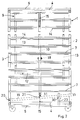
- the rack carriage 1 which can be moved into a rack oven, consists of a front and a rear rectangular frame 2, 3 and longitudinal connectors 4 provided at all four corners. All parts consist of square tube. U-rails 5,6 are attached at the top and bottom in the middle, which guide the rack trolley in the rack oven. The vertical profiles of the two frames support the support rails 7 for the baking trays (not shown).
- the lifting frame 9 contains only two vertical guide tubes 10, which are connected to one another by cross members 11 at the top and bottom.
- a horizontal strut 12 extends from the guide tubes 10 in the lower quarter, which connects to the vertical profiles 13 manufactures, which in turn connect and stiffen the slide-in strips 14 for the grille.
- the lifting frame 9 is guided by upper and lower columns 15, which are screwed to the longitudinal connectors 4 of the frame carriage.
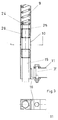
- the guides are shown in detail in Fig.3.
- the connection between the guide tubes 10 and the lower crossmember 11 is produced by an angle 16 screwed with hexagon screws 31, 32, which is welded with its vertical leg to the guide tube 10 designed as a square tube.
- the pillars 15, on the other hand, consist of round solid material, into which four grooves are screwed in at intervals for inserting circlips 25. These circlips hold sliders 26 made of Teflon or a similar well self-lubricating polyamide.
- a compression spring 17 is supported with the interposition of a square disk 24, the upper end of which is intercepted by a stud screw 18 passing through the guide tube 10. In this way, the compression springs always push the lifting frame into the upper release position.
- a foot lever 19 arranged in the lower middle of the carriage serves to lower the lifting frame 10, the rear bearing 20 of which lies above the rear lower frame crossbar of the frame carriage.
- a short two-articulated lever 21 serves as a connection to the lifting frame 9, which therefore makes it possible to actively lift the lifting frame if the compression springs fail.
- a square column 23 which is mounted on the lower U-guide rail 5 of the frame carriage 1, serves as a guide for the adjustable stop 22. It is provided with two rows of holes 27 set in the gap, into which the adjusting bolt 28 to be secured by a bow spring 29 can be inserted.
- the square sleeve 30, which is displaceably movable on the square column 23, has two bores corresponding to the two rows of holes 27.
- a stop bracket 35 is mounted by means of a spring-loaded bolt 34 so that it is with his knee through its own weight against the angle 36 below. In this position, it is receivable for the foot lever 19.
- the stop bracket 35 is raised so that the latch 37 of its vertical leg can grip over the projection 38 on the foot lever. If you now let go of the foot pedal, then the spring force of the lifting frame pulls the angle with its hinge pin 34 in the elongated holes up to the stop.
- the foot pedal is now locked. The foot pedal can always be lowered into this preset working position.
- the foot lever is only pressed down briefly.
- the stop angle tilts due to its center of gravity to the right and causes the latch to release the projection. This releases the foot pedal and, together with the lifting frame, is pulled upwards by spring force.
- the guides are reversed by forming the pillars as short pieces of pipe in which the guide rods slide.
- a vertical saw toothed rack can be provided, into which a spring-loaded catch engages at the set stop.
- the catch is equipped with a pull hook.
- the foot pedal can also be locked by friction.
- a friction surface pivotable about a lower articulation point is provided, which is pulled against a rigid counter surface by an upper transverse tension spring.
- the horizontal pedal surface near the joint point is actuated to trigger.
Landscapes
- Life Sciences & Earth Sciences (AREA)
- Engineering & Computer Science (AREA)
- Food Science & Technology (AREA)
- Baking, Grill, Roasting (AREA)
Priority Applications (1)
| Application Number | Priority Date | Filing Date | Title |
|---|---|---|---|
| EP91113480A EP0527252A1 (fr) | 1991-08-12 | 1991-08-12 | Châssis de support pour four à plateaux de cuisson |
Applications Claiming Priority (1)
| Application Number | Priority Date | Filing Date | Title |
|---|---|---|---|
| EP91113480A EP0527252A1 (fr) | 1991-08-12 | 1991-08-12 | Châssis de support pour four à plateaux de cuisson |
Publications (1)
| Publication Number | Publication Date |
|---|---|
| EP0527252A1 true EP0527252A1 (fr) | 1993-02-17 |
Family
ID=8207036
Family Applications (1)
| Application Number | Title | Priority Date | Filing Date |
|---|---|---|---|
| EP91113480A Withdrawn EP0527252A1 (fr) | 1991-08-12 | 1991-08-12 | Châssis de support pour four à plateaux de cuisson |
Country Status (1)
| Country | Link |
|---|---|
| EP (1) | EP0527252A1 (fr) |
Cited By (1)
| Publication number | Priority date | Publication date | Assignee | Title |
|---|---|---|---|---|
| CN104622318A (zh) * | 2015-03-19 | 2015-05-20 | 洪景波 | 一种正反旋转升降自动定位烧烤炉 |
Citations (4)
| Publication number | Priority date | Publication date | Assignee | Title |
|---|---|---|---|---|
| DE2459479A1 (de) * | 1974-12-16 | 1976-07-01 | Debag Deutsche Backofenbau | Baeckereibetriebsverfahren |
| DE3027875A1 (de) * | 1980-07-23 | 1982-02-25 | Karl Ahlborn Maschinenfabrik Kg, 3432 Grossalmerode | Vorrichtung zum beschicken von backoefen |
| DE8812032U1 (de) * | 1988-05-05 | 1988-11-17 | Karl Ahlborn Maschinenfabrik Kg, 3432 Grossalmerode | Beschickungsvorrichtung für einen Backschragen |
| DE8906000U1 (de) * | 1989-05-13 | 1989-07-13 | Huth, Heinz D., 6251 Burgschwalbach | Gestellwagen für Stikkenöfen |
-
1991
- 1991-08-12 EP EP91113480A patent/EP0527252A1/fr not_active Withdrawn
Patent Citations (4)
| Publication number | Priority date | Publication date | Assignee | Title |
|---|---|---|---|---|
| DE2459479A1 (de) * | 1974-12-16 | 1976-07-01 | Debag Deutsche Backofenbau | Baeckereibetriebsverfahren |
| DE3027875A1 (de) * | 1980-07-23 | 1982-02-25 | Karl Ahlborn Maschinenfabrik Kg, 3432 Grossalmerode | Vorrichtung zum beschicken von backoefen |
| DE8812032U1 (de) * | 1988-05-05 | 1988-11-17 | Karl Ahlborn Maschinenfabrik Kg, 3432 Grossalmerode | Beschickungsvorrichtung für einen Backschragen |
| DE8906000U1 (de) * | 1989-05-13 | 1989-07-13 | Huth, Heinz D., 6251 Burgschwalbach | Gestellwagen für Stikkenöfen |
Cited By (1)
| Publication number | Priority date | Publication date | Assignee | Title |
|---|---|---|---|---|
| CN104622318A (zh) * | 2015-03-19 | 2015-05-20 | 洪景波 | 一种正反旋转升降自动定位烧烤炉 |
Similar Documents
| Publication | Publication Date | Title |
|---|---|---|
| EP2870895B1 (fr) | Tablette pivotante pour un meuble | |
| EP0012231B1 (fr) | Gril repliable et portatif à grille réglable en hauteur | |
| DE2210492C3 (de) | Krankenfahrstuhl | |
| DE2646177B1 (de) | Vorrichtung zur Hoeheneinstellung eines Klapptisches,-stuhles,-hockers o.dgl. | |
| EP0193730A2 (fr) | Accessoire pour baignoire | |
| EP0527252A1 (fr) | Châssis de support pour four à plateaux de cuisson | |
| DE2524962A1 (de) | Oberschrank | |
| EP0331976B1 (fr) | Support d'appareil | |
| EP1284710B1 (fr) | Siege pour accouchement | |
| CH662101A5 (de) | Vorrichtung zum wahlweisen absetzen von transportablen behaeltern, maschinen oder geraeten auf der ladepritsche eines lastfahrzeuges oder auf dem boden. | |
| DE19549345A1 (de) | Grill mit verstellbarem Gargutträger | |
| DE2127309A1 (de) | Durchlaufregal | |
| DE4006829A1 (de) | Gestellwagen fuer stikkenoefen | |
| DE38456C (de) | Verstellbarer Stuhl | |
| EP2273201A2 (fr) | Système téléscopique et tiroir pour support de plats | |
| DE4227038C2 (de) | Arbeitstisch, insbesondere Schreibtisch | |
| DE2416879C3 (de) | Müllpressbehälter | |
| DE9205372U1 (de) | Höhenverstellbarer Stuhl für Kinder | |
| DE3522175C2 (fr) | ||
| DE2447207A1 (de) | Werkschrank | |
| DE8906000U1 (de) | Gestellwagen für Stikkenöfen | |
| DE4002149C1 (en) | Support arm for stretcher mounting frames - has movable holder, formed by lever foldable about axis parallel to stretcher length | |
| WO2017125244A1 (fr) | Unité de distribution de produits pour le prélèvement en libre-service de pain, de petits pains, de baguettes ou de produits de boulangerie similaires | |
| DE2701043B2 (de) | Sitzgruppe mit höhenverstellbarer Tischplatte zur Verwendung als Bett | |
| DE1809240C3 (de) | Kinderstuhl |
Legal Events
| Date | Code | Title | Description |
|---|---|---|---|
| PUAI | Public reference made under article 153(3) epc to a published international application that has entered the european phase |
Free format text: ORIGINAL CODE: 0009012 |
|
| AK | Designated contracting states |
Kind code of ref document: A1 Designated state(s): AT CH DE ES FR IT LI NL |
|
| STAA | Information on the status of an ep patent application or granted ep patent |
Free format text: STATUS: THE APPLICATION IS DEEMED TO BE WITHDRAWN |
|
| 18D | Application deemed to be withdrawn |
Effective date: 19930818 |