EP0527318A2 - Koksovenreparatur - Google Patents
Koksovenreparatur Download PDFInfo
- Publication number
- EP0527318A2 EP0527318A2 EP92110934A EP92110934A EP0527318A2 EP 0527318 A2 EP0527318 A2 EP 0527318A2 EP 92110934 A EP92110934 A EP 92110934A EP 92110934 A EP92110934 A EP 92110934A EP 0527318 A2 EP0527318 A2 EP 0527318A2
- Authority
- EP
- European Patent Office
- Prior art keywords
- module
- cast
- large size
- repair
- modules
- Prior art date
- Legal status (The legal status is an assumption and is not a legal conclusion. Google has not performed a legal analysis and makes no representation as to the accuracy of the status listed.)
- Ceased
Links
- 230000008439 repair process Effects 0.000 title claims abstract description 96
- 239000000571 coke Substances 0.000 title claims abstract description 74
- 238000010438 heat treatment Methods 0.000 claims abstract description 88
- 239000000463 material Substances 0.000 claims abstract description 85
- 239000011449 brick Substances 0.000 claims abstract description 41
- 238000000034 method Methods 0.000 claims abstract description 29
- XLYOFNOQVPJJNP-UHFFFAOYSA-N water Substances O XLYOFNOQVPJJNP-UHFFFAOYSA-N 0.000 claims abstract description 21
- 238000010304 firing Methods 0.000 claims abstract description 13
- 230000035939 shock Effects 0.000 claims abstract description 12
- 238000002156 mixing Methods 0.000 claims abstract description 9
- 239000011823 monolithic refractory Substances 0.000 claims abstract description 9
- 238000011068 loading method Methods 0.000 claims abstract description 4
- 238000004939 coking Methods 0.000 claims description 60
- 239000007789 gas Substances 0.000 claims description 25
- 206010022000 influenza Diseases 0.000 claims description 24
- 239000000203 mixture Substances 0.000 claims description 19
- 238000005299 abrasion Methods 0.000 claims description 12
- 238000007689 inspection Methods 0.000 claims description 12
- 238000011049 filling Methods 0.000 claims description 3
- 239000002737 fuel gas Substances 0.000 claims 3
- 238000009835 boiling Methods 0.000 claims 2
- VYPSYNLAJGMNEJ-UHFFFAOYSA-N Silicium dioxide Chemical compound O=[Si]=O VYPSYNLAJGMNEJ-UHFFFAOYSA-N 0.000 abstract description 34
- 239000000377 silicon dioxide Substances 0.000 abstract description 17
- 239000011819 refractory material Substances 0.000 abstract description 4
- 238000005266 casting Methods 0.000 description 28
- 238000013461 design Methods 0.000 description 13
- 239000000835 fiber Substances 0.000 description 5
- 239000004570 mortar (masonry) Substances 0.000 description 4
- 238000005192 partition Methods 0.000 description 4
- 239000006227 byproduct Substances 0.000 description 3
- 239000003245 coal Substances 0.000 description 3
- 238000001035 drying Methods 0.000 description 3
- 238000000465 moulding Methods 0.000 description 3
- 229910000831 Steel Inorganic materials 0.000 description 2
- 230000015572 biosynthetic process Effects 0.000 description 2
- 238000004140 cleaning Methods 0.000 description 2
- 230000008602 contraction Effects 0.000 description 2
- 238000001816 cooling Methods 0.000 description 2
- 238000005336 cracking Methods 0.000 description 2
- 230000006866 deterioration Effects 0.000 description 2
- 239000004615 ingredient Substances 0.000 description 2
- 238000009434 installation Methods 0.000 description 2
- 238000009413 insulation Methods 0.000 description 2
- 238000004519 manufacturing process Methods 0.000 description 2
- 239000002002 slurry Substances 0.000 description 2
- 239000010959 steel Substances 0.000 description 2
- 229910001018 Cast iron Inorganic materials 0.000 description 1
- 235000009161 Espostoa lanata Nutrition 0.000 description 1
- 240000001624 Espostoa lanata Species 0.000 description 1
- 235000019892 Stellar Nutrition 0.000 description 1
- 238000002485 combustion reaction Methods 0.000 description 1
- 230000001419 dependent effect Effects 0.000 description 1
- 238000011161 development Methods 0.000 description 1
- 238000007667 floating Methods 0.000 description 1
- 239000003546 flue gas Substances 0.000 description 1
- 238000003197 gene knockdown Methods 0.000 description 1
- 239000012774 insulation material Substances 0.000 description 1
- 230000007774 longterm Effects 0.000 description 1
- 238000012423 maintenance Methods 0.000 description 1
- 239000002184 metal Substances 0.000 description 1
- 229910052751 metal Inorganic materials 0.000 description 1
- 238000004806 packaging method and process Methods 0.000 description 1
- 238000012545 processing Methods 0.000 description 1
- 230000000750 progressive effect Effects 0.000 description 1
- 238000010791 quenching Methods 0.000 description 1
- 230000000171 quenching effect Effects 0.000 description 1
- 238000007789 sealing Methods 0.000 description 1
- 238000005204 segregation Methods 0.000 description 1
- 125000006850 spacer group Chemical group 0.000 description 1
- 239000007921 spray Substances 0.000 description 1
- 238000005507 spraying Methods 0.000 description 1
- 239000007858 starting material Substances 0.000 description 1
- 238000003860 storage Methods 0.000 description 1
- 210000002105 tongue Anatomy 0.000 description 1
- 239000003039 volatile agent Substances 0.000 description 1
- 239000002023 wood Substances 0.000 description 1
Images





Classifications
-
- C—CHEMISTRY; METALLURGY
- C10—PETROLEUM, GAS OR COKE INDUSTRIES; TECHNICAL GASES CONTAINING CARBON MONOXIDE; FUELS; LUBRICANTS; PEAT
- C10B—DESTRUCTIVE DISTILLATION OF CARBONACEOUS MATERIALS FOR PRODUCTION OF GAS, COKE, TAR, OR SIMILAR MATERIALS
- C10B29/00—Other details of coke ovens
- C10B29/06—Preventing or repairing leakages of the brickwork
-
- C—CHEMISTRY; METALLURGY
- C10—PETROLEUM, GAS OR COKE INDUSTRIES; TECHNICAL GASES CONTAINING CARBON MONOXIDE; FUELS; LUBRICANTS; PEAT
- C10B—DESTRUCTIVE DISTILLATION OF CARBONACEOUS MATERIALS FOR PRODUCTION OF GAS, COKE, TAR, OR SIMILAR MATERIALS
- C10B29/00—Other details of coke ovens
- C10B29/02—Brickwork, e.g. casings, linings, walls
Definitions
- the present invention relates generally to a large size cast monolithic refractory module having high dimensional stability, good compressive loading, and good thermal shock resistance in the range of -20° to 1565° Celsius, which module may be used in the repair of a coke oven.
- This invention also relates to a process for making such a large size cast module.
- Coke is produced by heating pulverized coal in an air free environment for a period of time.
- coke is produced in a coke oven battery which includes a plurality of side-by-side coking chambers which are separated from each other by heating walls.
- the heating walls and the coking chambers extend from the pusher side to the coke side of the battery.
- the battery may include 40 to 100 or more side-by side coking chambers, each chamber being from 3 to 6 metres high, typically 14 metres long, and approximately 1/2 metre wide. There is a slight taper to the width of each chamber so that coal which has been coked within the chamber may be pushed out.
- Each heating wall is typically built up from a number of horizontally extending courses of silica bricks, the bricks being assembled to define vertically extending flues within the heating walls, which flues cycle between heating and drafting conditions. There is a gas nozzle at the bottom of each flue. There may be a six bricks or more in each course for each flue. Thus, in a heating wall having twenty-six courses and twenty-eight flues there may be over 4,300 bricks, each brick being location specific.
- a conventional coke oven will be described in greater detail below with reference to the drawings of this application.
- US Patent 2,476,305 discloses that a heating wall in a coke oven may be repaired by replacing individual bricks.
- US Patent 4,452,749 also discloses a repair wherein individual bricks are replaced, the bricks in this case being molded from a castable refractory material which expands to only a negligible degree during heating up.
- this patent only discloses the use of bricks having essentially the same size as the bricks which they are replacing as it was not known how to cast large refractory shapes suitable for use in a coke oven before the present invention.
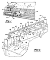
- FIG. 1 is a perspective view of the coke side of a coke oven battery which may be repaired in accordance with the principles of the present invention.
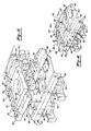
- FIG. 2 is a perspective view of a portion of a coke oven illustrating the initial phases of the rebuild of an end portion of a heating wall which extends between two adjacent coking ovens, the old brickwork having been removed and a first large size cast monolithic refractory module having been installed over existing floor brick, and also illustrating how the first cast module of this invention is tied in with existing silica brickwork when a four flue repair is being performed.
- FIG. 3 is a view similar to FIG. 2 but illustrating a second large size cast module in position above the first cast module shown in FIG. 2.
- FIG. 4 is a side elevational view of a heating wall having an end portion thereof undergoing repair, the old brickwork having been removed, and thirteen cast modules of this invention having been installed adjacent the old brickwork in the heating wall, special tie-in face castings being positioned between the modules of this invention and the old brickwork.
- FIG. 5 is a view similar to FIG. 3 but showing a further form of a large size cast module of this invention which is to be mounted on the prior cast modules shown in FIG. 4, the form of cast module shown in FIG. 5 having partition walls between adjacent flues removed so that gases within one flue can flow into another flue.
- FIG. 6 is an enlarged side elevational view of the upper portion of the repair, portions being broken out to facilitate an understanding, the sectional portion of this figure being taken generally along the line 6-6 in FIG. 5.
- FIG. 7 is a perspective view similar to FIGS. 3 and 5 but illustrating a further form of a large size cast module, which form is utilized to close off the tops of the flues with the exception of flue inspection holes.
- FIG. 8 is a side view similar to FIG. 6 but illustrating the structure therein after inspection port modules illustrated in FIG. 7 have been added, the sectional portion of this figure being taken generally along the line 8-8 in FIG. 7.
- FIG. 9 is a perspective view of two adjacent heating walls which have been repaired to the extent illustrated in FIG. 8 and further showing a first set of cast interfitting ceiling modules which are utilized to perform a ceiling repair, the first set of ceiling modules being shown in exploded form.
- FIG. 10 is a view similar to FIG. 9 but showing the first set of ceiling modules assembled onto the modules shown in FIGS. 8 and 9.
- FIG. 11 is a sectional view taken generally along the line 11-11 in FIG. 10.
- FIG. 12 is a sectional view taken generally along the line 12-12 in FIG. 10.
- FIG. 13 is a view similar to FIG. 11 but showing a second course of the ceiling modules shown in FIG. 9 added to the structure shown in FIG. 10.
- FIG. 14 is a sectional view taken generally along the line 14-14 in FIG. 13.
- FIG. 15 is a view similar to FIG. 9 but showing in exploded view of a second set of interfitting ceiling modules which are to be added to the structure shown in FIG. 13.
- FIG. 16 is a view similar to FIG. 13 but showing the course of modules illustrated in FIG. 15 assembled to the structure shown in FIG. 13.
- FIG. 17 is a view taken generally along the line 17-17 in FIG. 16.
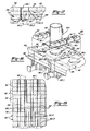
- FIG. 18 is a further perspective view illustrating in part the manner in which the roof of the coke oven is repaired, this view illustrating additional inspection port castings being added to the structure shown in FIG. 16 and further showing a fiber tube which will be utilized in the formation of a gas off-take which will in turn be connected to a gas take-off pipe (standpipe).
- a gas take-off pipe standpipe
- FIG. 19 is a sectional view taken generally along the line 19-19 in FIG. 18 but further showing a plurality of inspection port castings assembled onto the roof structure.
- FIG. 20 is a perspective view showing a complete roof assembly with a castable refractory poured between the inspection port modules and the fiber tube shown in exploded view in FIG. 18 and further showing a standpipe in phantom.
- FIG. 21 is a section taken generally along the line 21-21 in FIG. 20, but showing the standpipe in full lines.
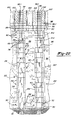
- FIG. 22 is a sectional view of a coke oven wherein the end portions of two adjacent heating walls have been repaired as well as the ceiling above the heating walls, this view being taken generally along the line 22-22 in FIG. 1.
- FIG. 23 is a side elevational view of a portion of a heating wall showing the manner in which it would be repaired if only a three flue end repair were being done instead of the four flue end repair shown in FIGS. 2 through 20.
- FIG. 24 is a plan view of the large size two flue cast module which will be used in the three flue repair shown in FIG. 23.
- FIG. 25 is a side elevational view showing a seven flue repair with tie-in face castings used for the seventh flue.
- FIG. 26 is a plan view of two adjacent large size three flue cast modules used in the seven flue repair shown in FIG. 25.
- FIG. 27 shows a stagger block arrangement for the nine flue repair wherein three separate large size cast modules are utilized to create a six flue configuration.
- FIG. 28 is a side elevational view showing a ten flue repair.
- FIGS. 29 and 30 are plan views of two separate courses of large size cast modules which may be utilized in the ten flue repair shown in FIG. 28, FIG. 29 representing the principal large size cast modules used in the repair, and FIG. 30 representing the tie-in or stagger modules.
- FIG. 31 is a graph showing how the mortar mix used in forming the various large size cast monolithic refractory modules of this invention is fired.
- a portion of a coke oven battery is illustrated, the coke oven battery being indicated generally at 10.
- the form of a coke oven battery illustrated is sometimes referred to as a by-products coke oven since the volatiles driven off during the coking process flow from standpipes 12 to a collector main 14 for subsequent processing, the standpipe and collector main being mounted on the roof 15.
- the coke oven battery includes a plurality of coking chambers 16, each of the coking chambers extending the full length of the coke oven battery from the pusher side (not shown) to the coke side 18.
- Each coking chamber 16 may be 14 metres in length, and also may have a height of 3 to 6 metres, 5 metres being typical.
- the coking chambers are built with a slight taper, the width at the pusher side being for example 40 centimetres and the width at the coke side being 48 centimetres.
- the coking chambers 16 are closed by coke oven doors (not shown) which may be removed by a door machine 20.
- the coking chambers 16 are separated from each other by heating walls indicated generally at 22.
- Each heating wall is typically formed from courses of silica bricks indicated generally at 24, there being hundreds of bricks to each course.
- Each of the heating walls is built with a plurality of flues 26, which flues typically are alternated between heating cycles and drafting cycles.
- the floor of the coking chambers 16 as well as the heating walls 22 are supported by a floor structure indicated generally at 28 (FIG. 2).
- Heated air and gas are introduced into the flues through nozzles 30 (FIG. 22) and air ports at the bottom of the flues.
- the air and gas are ignited, the burning gas in turn heating the heating walls to a temperature typically in the range of 1150° to 1375° Celsius.
- a pusher (not shown) is introduced into the coking chamber to push the coke from within the coking chamber, the coke being discharged on the coke side through a coke guide, somewhat schematically shown at 34, and then into a quenching car 36.
- a novel large size cast monolithic refractory module is formed from a material of the type having a high dimensional stability and good thermal shock resistance in the range from -20° to 1565° Celsius.
- the cast refractory module of this invention encompasses at least one entire flue from one side of the heating wall to the other side.
- the large size, cast module preferably encompasses two or more flues.
- a large size cast refractory module made in accordance with the principles of the invention is indicated generally at 40.
- a large size cast module for the purposes of this application is one that has a width of at least 35 centimetres, a height of at least 13.5 centimetres, and a length of at least 35 centimetres, the smallest large size cast module contemplated by this invention being indicated at 42 in FIGS. 25 and 27.
- the large size first cast module 40, shown in FIG. 3, is considerably larger than the minimum sizes of a large size cast module set forth above. Although it has a width only slightly larger than that specified, it has a height approximately twice the height specified, and a length approximately three times the size specified.
- Harbison Walker Descon S97 One material used for making blocks which has the desired properties, namely a thermal expansion of less than 0.5%, good compressive loading, and a service range of up to 1565° Celsius is Harbison Walker Descon S97, which material is believed to be made in accordance with the principles set forth in US Patent 4,506,025. This material also has good abrasion resistance to coke as it is being pushed past its surface. The material as received from the manufacturer presents several variables in the mix that have to be watched for. This can make the difference between making a block that can be properly "fired” in a furnace and used for an extended period of time in a coke oven and one that fails during firing or after installation in a furnace. The inventor and the foreman in charge of the module making are not sure whether this is due to variables in the mixing of materials by the manufacturer, or has to do with variations of the ingredients used by the manufacturer, Harbison, or both.
- the mixer at the module or block making site is cleaned out to bare metal at the end of the day for the next day. There is no cleaning necessary between batches of the material being mixed on the same day of operation to fill block molds. Several block molds are filled in the course of one day without cleaning the mixer between batches for the filling of the molds.
- the normal starting point is 1 2 3 litres of water per bag. Normal wet mixing time is 5 minutes. It can be as short as 4 minutes and as long as 7 to 8 minutes.
- the mixer is dumped into a receiving pan. The mixed material is then shoveled by hand into the mold.
- the mold When the first material is added to the mold, the mold is vibrated on a vibrating table. Vibration is continued until the mold is completely filled with additionally mixed batches. It will take at least three batches from the mixer, twelve bags, to fill the block mold for the casting 40. It may be necessary to make a one or two bag mix to complete filling the mold.
- a floating trowel is used to smooth and level the material in the mold while vibrating. Vibration is stopped when the mold is full and the material leveled.
- the vibrating table is made of 1.25 - 1.30 centimetre plate steel supported by Airmount agitators. The vibrator is sized to impart to the table suitable vibration. A vibrator having a power output in the range of 1.0 - 1.2 kilowatts and capable of imparting 3,600 impacts/minute using a 560 kilogram force vibrator has been found to be satisfactory.
- the amount of water in the material in the mix is critical. The normal starting point is 1 2 3 litres. If the material appears to be too wet on vibrating in the mold, the next batch may have 59 to 118 millilitres of water removed from the mix. If it is still found to be too "wet", there is a fault in the mix. If it is still found to be too dry, up to 59 millilitres of additional water may be added. Again, above this point indicates a problem with the mix as furnished by the supplier. The addition or deduction of water is a judgment made by the foreman. This is done by observing the rise of water in the first batch shoveled into the mold upon initial vibration. The water tends to rise through the material. A feel of the material in the mold is also used in making this judgment.
- the mold is stripped from the cast material and then the block of material is placed in a firing oven where it is progressively heated through the gradient shown in FIG. 31.
- the large size cast structure is then cooled at an average cooling rate of 16 2 3 ° per hour until it attains ambient. However, other cool down rates may be used.
- the large size cast refractory module is now ready to be installed.
- Free Kast 896 Another material which may be used for forming large size cast refractory modules is Free Kast 896, which is manufactured by the Chicago Firebrick Company. According to the packaging which accompanies this material, it is manufactured under US Patent 4,921,536. This material is received from the supplier in 50-pound (22 2 3 kilogram) bags. The material is mixed in a clean mixer which has been wet with a pail of water, the water having been dumped prior to the starting of the mixing operation. Water for the material is added to the mixer with the mixer on, 1.36 litres of water being used per bag of material. (The mixer being used at the present time can only accept three bags of material.) Three bags of the Free Kast 896 is then added to the mixer with the water.
- the mold which is being used to form the large size cast refractory module of this invention is completely filled before vibrating. Vibration time of the mold is not as critical as with Descon S97. Normally, the filled mold is vibrated for the length of time that it takes to smooth and trowel the mix in the mold. Thus, as the mold may take up to twelve bags of material, it is necessary to continue to mix and fill the mold until a sufficient fill has been achieved. If the mix was too wet to start out with, it has been learned that putting the mold with the material in it into a drying oven over night will prevent cracking of the casting in handling.
- the mold is removed after the casting is removed from the drying oven. Wood molds are used for some of the castings. After the mold has been stripped from the casting or block, it can go directly to the firing oven, or it can go into storage until the firing oven is ready for a group of blocks. The firing process for this material is the same as for the Descon material. The method of mixing and molding of this material for the shapes being made is different than the manufacturer suggests and incorporates the thoughts of the inventor.
- FIGS. 2 through 22 illustrate the process for making a four flue repair as well as various special shapes of the large size cast modules used for rebuilding the heating walls between adjacent coking chambers, various special shapes of ceiling repair modules used for the ceiling repair and the flue modules which extend to the top of the roof 15 of the coke oven battery.
- a number of preliminary steps are taken, which steps are not illustrated in the drawings. These preliminary steps are conventional steps used in any coke oven end wall repair.
- the coke oven doors and coke oven door frames are removed at the ends of the adjacent coking chambers where the end wall repair is to be performed.
- the repair area is insulated by building a brick bulkhead 38 which extends between existing brickwork across the width of the heating chamber.
- insulation is applied to the side walls of the heating walls to either side of the coking chambers.
- the I-beam 44 at the end of the heating wall is cut off at the floor level as indicated at weld line 46 and the portion above the line 46 through the roof 15 is removed. (although the I-beam is shown in FIGS.
- the coke oven chamber has a 7.5 centimetre taper, being 7.5 centimetres wider at the coke side than at the pusher side, it is also necessary to dimension these bricks to take into account the taper of the coking chamber.
- every other course is different to provide for stagger of the silica brick shapes.
- the old brickwork which is to be repaired is removed so that only brickwork necessary to define one side of the fourth flue is left in place, which for the top course of old brickwork illustrated in FIG. 3 are the various shapes shown.
- thirteen large size cast refractory modules 40 of a first generally identical configuration are employed.
- the difference between the first thirteen modules is that the bottom first large size cast refractory module 50 is provided with clean out ports 52 whereas the other first large size cast refractory modules 40 are not provided with clean out ports.
- the modules 40 and 50 are the same.
- each of the modules is formed of a structure which is of a generally rectangular parallelepiped form having first and second opposed vertically extending side walls 54 which are spaced apart from each other a distance substantially equal to the width of the heating wall being repaired at the location of the repair.
- Two clean out ports are provided in one of the side walls 54 and an additional clean out port is provided in the other side wall 54.
- the structure further includes first and second opposed generally vertically extending ends 56.
- the end 56 which is adapted to abut against a I-beam has the specific shape illustrated best in FIG. 26.
- the other end 56 is adapted to be placed into contact with the tie-in face castings 58 to form the fourth flue, the other end being of the shape illustrated.
- Partitions 60 extend from one side wall 54 to the other to define with the ends 56 three flues 26.
- casting 40 (as well as the castings 50), are provided with notches 56.1 which may cooperate corresponding notches in the tie-in face castings 58 to prevent the flow of gases between the coking chamber 16 and the fourth flue adjacent the right-hand end (as illustrated) of the large size cast module.
- the large size cast module is provided with upper and lower generally horizontal surfaces 62. The distance between the horizontal surfaces is at least equal in all large size cast modules to one course of old brickwork, and in the preferred form of the first large size cast modules illustrated in the FIGS. 2, 3, and others, the vertical distance is equal to two courses of old brickwork.
- the large size cast module is made from a material which has high dimensional stability, negligible expansion on heating, good compressive strength, and good thermal shock resistance in the range of -20° to 1565° Celsius.
- the surface of the large size module should be resistant to abrasion such as may be present during the push of coke from the coking chamber at the end of the coking process. While such materials are readily available, it has not been practical in the past to cast large size modules such as the type shown at 40 and 50 as prior experience has shown that such modules will fail when placed in the oven or, more likely, will fail during the initial firing by either cracking or exploding.
- the smaller shapes, such as the tie-in face castings 58 may be made by conventional molding and firing practices such as the type recommended by the manufacturers of the material used, for example by the manufacturer of the Harbison Walker Descon S97 material.
- the repair is made, it is typically necessary to cut the tie-in face castings to size on the job site.
- a compressive mortar is placed between the joint formed between the tie-in face casting 58 and the old brickwork 24 as the old brickwork will expand when the end of the oven is brought back up to coke oven temperatures after repair and this expansion must be accommodated at this location.
- the brick layer need only be concerned with the expansion of the silica brick.
- second large size cast module which is a transitional module utilized to cause the flue gases to flow from one flue to another.
- a hairpin design is illustrated where one flue is used for heating and the immediately adjacent one is used for drafting.
- other flue designs are well known in the art.
- it is necessary to provide a second design of large size cast module for use at the top of the flues the second large size cast module being indicated generally by reference numeral 68. In the design illustrated, two large size cast modules 68 are employed.
- the second large size cast module 68 will be made preferably from the same material as the first one 40, but it may also be made from another material which has same abrasion resistance as the material for the first large size cast modules 40. Thus, as the second large size cast module 68 will not be above the coke surface, it will be subject to abrasion during a push.
- the second large size cast modules also have first and second opposed vertically extending side walls 70 which are spaced apart from each other the same amount as the side walls of the first large cast modules upon which it sits. It also has first and second ends 72 and upper and lower horizontal surfaces 74.
- the distance between the horizontal surfaces 74 is equal to only one course of brick.
- the second cast module follows the same design as the first cast module except that its height is 1/2 of that of the first cast module and also in that every other partition wall 60 is removed as at 78 to provide a passageway for gases between adjacent flues.
- the top of the heating wall is finished off by adding a third design of large size cast modules, the third large size cast module being indicated generally at 80.
- a two flue module 80.1 may be employed along with additional one flue modules.
- Each of the modules has side walls (no reference numeral) spaced away from each other the same distance as are the side walls 54 and 70 and additionally it has upper and lower horizontal surfaces spaced away from each other a distance equal to one course of old brickwork as are the horizontal surfaces 74 of the second cast modules.
- the two flue third large size cast module 80.1 is provided with an end which is adapted to abut against a I-beam.
- the two flue third large size module 80.1 is provided with a pair of inspection holes 82 which are spaced apart a distance equal to the distance between the nozzles 30.
- the right-hand end as viewed in FIG. 7, is provided with a notch for receiving a projection from a second one flue third large size cast module 80.2.
- An end third large size cast module 80.3 is provided, this module not being provided with a notch at its right-hand end.
- the lower surfaces of the third large size cast modules 80 are provided with tongues 64 which are adapted to be received within the grooves 64 on the second large size cast modules. However, the upper surface is flat. As can be seen from FIG. 7, it is not necessary to provide a face casting 58 in this course as the end of repair third large size cast module will rest directly upon the tie-in modules in the course below.
- a first set of interfitting ceiling repair modules are provided which have a height approximately equal to one course of old brickwork.
- This first set includes a first large size generally rectangular bridging ceiling repair module indicated generally at 84.
- the bridging module has opposed parallel side walls 84.1 spaced apart a distance greater than the width of a coking chamber but less than the sum of the widths of a coking chamber and a heating wall.
- the bridging module further includes opposed end walls 84.2.
- One of the end walls is provided with a semicircular cut-out 80.4 which will form a portion of a passageway for the passage of gases from the coking chamber to a standpipe which is to be disposed above the semicircular cut-out.
- the first set of ceiling repair modules further includes first and second large size opposed cross-shaped ceiling repair modules indicated generally at 86. Each of these modules is adapted to rest upon the top surface 80.2 of the third large size cast module and they will extend slightly above the heating chamber.
- the first set of interfitting ceiling repair modules is completed by a block ceiling repair module 88 which has opposed parallel side walls spaced apart a distance greater than the width of the coking chamber but less than the sum of the widths of a coking chamber and a heating wall, the repair module 88 having an end wall provided with a sloping surface 90 which is adapted to form a surface for the passageway which will lead from the coking chamber to a standpipe.
- the modules 84, 86, and 88 may be made of the same material as modules 40, 50, 68, and 80.
- each course of ceiling repair modules are additional flue modules 92.
- Each of the flue modules is provided with an aperture 92.1 which may be placed in alignment with a corresponding aperture 82 in one of the third large size cast modules.
- each cross-shaped module 86 may further be provided with other apertures 86.1 which may also be placed in alignment with corresponding apertures 82 in the third large size cast module 80.
- a second set of interfitting ceiling repair modules may be utilized, each of which includes a generally rectangular apertured ceiling repair module 96 which is adapted to be placed over the bridging module 84, the cross-shaped modules 86, and the block ceiling repair module 88 with a portion of the circular aperture 96.1 in the rectangular apertured ceiling repair module 96 being in alignment with the semicircular cut-out of the first rectangular bridging module 84 to provide for a passageway for coke oven gases.
- Spacer modules 98 may be provided to either end of the module 96 and, in addition, flue modules 92 are provided to complete the course.
- the balance of the roof may now be completed by laying up additional courses of flue modules 92 until the last course is flush with the top of the roof of the battery.
- a fiber tube 100 is placed in position so that it extends slightly into the circular aperture in the rectangular aperture block 96 and then suitable material may now be poured into the space. It should be noted that as this material is not subject to either abrasion or to compressive loads that a number of suitable materials may be selected. However, as the fiber tube 100 is only used as a mold which will be consumed during the operation of the oven, it is necessary that the material 102 will mold to the desired shape and that once it has achieved its desired shape that it will retain its shape without undue expansion or contraction during operation.
- Suitable materials are well known in the art and in addition to the material set forth above, another suitable material may be Thermbond 2800-60 made by Stellar Materials, Inc.
- a standpipe 12 will be added, the ports or openings 92.1 in the flue modules will be closed with a suitable removable closure device, typically a cast iron cover. It will now be possible to reinstall the I-beam which was removed during the repair, the door frame, the door, and also to remove the bulkhead 38 and the insulation material.
- the first large size cast refractory module 104 When a three flue repair is to be made as shown in FIGS. 23 and 24, the first large size cast refractory module 104 will have the cross-sectional configuration shown in FIG. 24. These modules will be laid up in the manner shown in FIG. 3 with suitable tie-in face castings 58. When doing a seven flue repair, cast modules of the type shown in FIGS. 25, 26, and 27 will be utilized. Thus, as can be seen, at the I-beam end of the repair, first large size cast refractory modules 40 and 50 will be utilized, these modules being of the same type as utilized in the repair illustrated in FIGS. 2, 3, and 4.
- a further large size module such as that shown at 106 will also be utilized, this form of block having a cross-sectional configuration similar to that of modules 40 and 50 except that the left-hand end portion which would abut against the I-beam is eliminated and the flue formed between the side walls 54 and the left-hand partition 60 is left open. This is because the right-hand end of the casting 40 or 50 will form the left-hand wall portion for the fourth flue.
- a large size two flue casting 108 is employed, this casting having the same cross-section as the two flue casting shown in FIG. 24, a short large size three flue casting 110 of the configuration shown in FIG.
- the casting 42 is considered a large size casting in that it has a width equal to the width of the heating wall, a length equal to at least one flue, and a height at least equal to one course of old brickwork.
Landscapes
- Chemical & Material Sciences (AREA)
- Engineering & Computer Science (AREA)
- Materials Engineering (AREA)
- Oil, Petroleum & Natural Gas (AREA)
- Organic Chemistry (AREA)
- Furnace Housings, Linings, Walls, And Ceilings (AREA)
Applications Claiming Priority (2)
| Application Number | Priority Date | Filing Date | Title |
|---|---|---|---|
| US739318 | 1991-08-01 | ||
| US07/739,318 US5227106A (en) | 1990-02-09 | 1991-08-01 | Process for making large size cast monolithic refractory repair modules suitable for use in a coke oven repair |
Publications (2)
| Publication Number | Publication Date |
|---|---|
| EP0527318A2 true EP0527318A2 (de) | 1993-02-17 |
| EP0527318A3 EP0527318A3 (en) | 1993-07-14 |
Family
ID=24971749
Family Applications (1)
| Application Number | Title | Priority Date | Filing Date |
|---|---|---|---|
| EP19920110934 Ceased EP0527318A3 (en) | 1991-08-01 | 1992-06-27 | Improved coke oven repair |
Country Status (5)
| Country | Link |
|---|---|
| US (2) | US5227106A (de) |
| EP (1) | EP0527318A3 (de) |
| JP (1) | JPH05230466A (de) |
| CA (1) | CA2074762C (de) |
| MX (1) | MX9204383A (de) |
Cited By (6)
| Publication number | Priority date | Publication date | Assignee | Title |
|---|---|---|---|---|
| EP1067167A3 (de) * | 1999-07-05 | 2003-02-05 | Kawasaki Steel Corporation | Verfahren zur Reparatur eines Koksofen und Eintragsvorrichtung für Auskleidungsblöcke |
| GB2445855A (en) * | 2007-01-16 | 2008-07-23 | Vanocur Refractories L L C | Coke oven heating wall replacement using large size cast modules |
| WO2008108891A1 (en) * | 2007-03-02 | 2008-09-12 | Saturn Machine & Welding Co., Inc. | Method of and apparatus for replacing coke oven wall |
| FR2927630A1 (fr) * | 2008-02-15 | 2009-08-21 | Vanocur Refractories L L C | Reconstruction d'un four a coke |
| EP4416235A4 (de) * | 2021-10-15 | 2025-02-26 | Vanocur Refractories LLC | Kanal für eine heizwand einer koksofen- oder koksofenbatterie |
| LU507835B1 (en) | 2024-07-24 | 2026-01-26 | Paul Wurth Italia S P A | Coke oven heating wall repair, replacement or construction |
Families Citing this family (68)
| Publication number | Priority date | Publication date | Assignee | Title |
|---|---|---|---|---|
| US5227106A (en) * | 1990-02-09 | 1993-07-13 | Tonawanda Coke Corporation | Process for making large size cast monolithic refractory repair modules suitable for use in a coke oven repair |
| DE4231922A1 (de) * | 1992-09-24 | 1994-03-31 | Krupp Koppers Gmbh | Verfahren zur Erneuerung der Heizwände einer Koksofenbatterie |
| US5597452A (en) * | 1992-09-24 | 1997-01-28 | Robert Bosch Gmbh | Method of restoring heating walls of coke oven battery |
| US5687531A (en) * | 1995-02-14 | 1997-11-18 | North American Refractories Company | Horizontal flue technology for carbon baking furnace |
| US5685290A (en) * | 1996-08-19 | 1997-11-11 | P. Michael Collins | Combustion air kit |
| JP3939283B2 (ja) * | 2003-10-15 | 2007-07-04 | 守人 宇都宮 | ブロックおよびブロック連結具 |
| US20110083314A1 (en) * | 2007-03-02 | 2011-04-14 | Saturn Machine & Welding Co., Inc. | Method and apparatus for replacing coke oven wall |
| US7998316B2 (en) | 2009-03-17 | 2011-08-16 | Suncoke Technology And Development Corp. | Flat push coke wet quenching apparatus and process |
| US8266853B2 (en) * | 2009-05-12 | 2012-09-18 | Vanocur Refractories Llc | Corbel repairs of coke ovens |
| US9200225B2 (en) | 2010-08-03 | 2015-12-01 | Suncoke Technology And Development Llc. | Method and apparatus for compacting coal for a coal coking process |
| US8980069B2 (en) | 2011-11-17 | 2015-03-17 | Allied Mineral Products, Inc. | High temperature electrolysis cell refractory system, electrolysis cells, and assembly methods |
| IN2015KN00248A (de) | 2012-07-31 | 2015-06-12 | Suncoke Technology & Dev Llc | |
| US9243186B2 (en) | 2012-08-17 | 2016-01-26 | Suncoke Technology And Development Llc. | Coke plant including exhaust gas sharing |
| US9249357B2 (en) | 2012-08-17 | 2016-02-02 | Suncoke Technology And Development Llc. | Method and apparatus for volatile matter sharing in stamp-charged coke ovens |
| US9359554B2 (en) | 2012-08-17 | 2016-06-07 | Suncoke Technology And Development Llc | Automatic draft control system for coke plants |
| US9169439B2 (en) | 2012-08-29 | 2015-10-27 | Suncoke Technology And Development Llc | Method and apparatus for testing coal coking properties |
| PL2898048T3 (pl) | 2012-09-21 | 2020-11-16 | Suncoke Technology And Development Llc | Przetwarzanie w piecu koksowniczym o zmniejszonej wydajności z dzieleniem gazu zapewniające wydłużony cykl procesu |
| US9238778B2 (en) | 2012-12-28 | 2016-01-19 | Suncoke Technology And Development Llc. | Systems and methods for improving quenched coke recovery |
| WO2014105062A1 (en) | 2012-12-28 | 2014-07-03 | Suncoke Technology And Development Llc. | Systems and methods for removing mercury from emissions |
| US9476547B2 (en) | 2012-12-28 | 2016-10-25 | Suncoke Technology And Development Llc | Exhaust flow modifier, duct intersection incorporating the same, and methods therefor |
| US10047295B2 (en) | 2012-12-28 | 2018-08-14 | Suncoke Technology And Development Llc | Non-perpendicular connections between coke oven uptakes and a hot common tunnel, and associated systems and methods |
| US10883051B2 (en) | 2012-12-28 | 2021-01-05 | Suncoke Technology And Development Llc | Methods and systems for improved coke quenching |
| PL2938701T3 (pl) | 2012-12-28 | 2020-05-18 | Suncoke Technology And Development Llc | Pokrywy kominów upustowych i powiązane sposoby |
| US10760002B2 (en) | 2012-12-28 | 2020-09-01 | Suncoke Technology And Development Llc | Systems and methods for maintaining a hot car in a coke plant |
| US9193915B2 (en) * | 2013-03-14 | 2015-11-24 | Suncoke Technology And Development Llc. | Horizontal heat recovery coke ovens having monolith crowns |
| US9273250B2 (en) | 2013-03-15 | 2016-03-01 | Suncoke Technology And Development Llc. | Methods and systems for improved quench tower design |
| WO2015074003A1 (en) | 2013-11-15 | 2015-05-21 | Allied Mineral Products, Inc. | High temperature reactor refractory systems |
| CN103627409B (zh) * | 2013-11-29 | 2015-08-19 | 中冶天工集团有限公司 | 具有输出平衡压力的灌浆装置 |
| PL3090034T3 (pl) | 2013-12-31 | 2020-10-05 | Suncoke Technology And Development Llc | Sposoby dekarbonizacji pieców koksowniczych i powiązanych z nimi systemów i urządzeń |
| JP6280453B2 (ja) * | 2014-06-11 | 2018-02-14 | 株式会社メガテック | コークス炉燃焼室の壁体と天井およびその燃焼室に隣接する炭化室の天井の補修方法 |
| KR102410181B1 (ko) | 2014-06-30 | 2022-06-20 | 선코크 테크놀러지 앤드 디벨로프먼트 엘엘씨 | 모노리스 크라운을 갖는 수평 열회수 코크스 오븐 |
| UA123494C2 (uk) | 2014-08-28 | 2021-04-14 | Санкоук Текнолоджі Енд Дівелепмент Ллк | Вдосконалені режими горіння для операцій коксування |
| KR102441123B1 (ko) * | 2014-09-15 | 2022-09-06 | 선코크 테크놀러지 앤드 디벨로프먼트 엘엘씨 | 모놀리스 요소 구성을 갖는 코크스로 |
| US9499950B1 (en) * | 2015-11-06 | 2016-11-22 | Lee A. Smith | Revetment block mat with linear sides |
| US10975310B2 (en) | 2014-12-31 | 2021-04-13 | Suncoke Technology And Development Llc | Multi-modal beds of coking material |
| WO2016109854A1 (en) | 2015-01-02 | 2016-07-07 | Suncoke Technology And Development Llc | Integrated coke plant automation and optimization using advanced control and optimization techniques |
| US11060032B2 (en) | 2015-01-02 | 2021-07-13 | Suncoke Technology And Development Llc | Integrated coke plant automation and optimization using advanced control and optimization techniques |
| WO2017117282A1 (en) | 2015-12-28 | 2017-07-06 | Suncoke Technology And Development Llc | Method and system for dynamically charging a coke oven |
| JP6573837B2 (ja) * | 2016-02-05 | 2019-09-11 | 株式会社メガテック | コークス炉の燃焼室の補修方法 |
| EP3416920B1 (de) | 2016-02-18 | 2024-04-03 | Fosbel, Inc. | Glasschmelzofenregeneratoren aus einteiligen lasttragenden wandblöcken |
| JP7109380B2 (ja) | 2016-06-03 | 2022-07-29 | サンコーク テクノロジー アンド ディベロップメント リミテッド ライアビリティ カンパニー | 産業施設において改善措置を自動的に生成する方法およびシステム |
| CN110832055B (zh) | 2017-05-23 | 2023-02-03 | 太阳焦炭科技和发展有限责任公司 | 用于修补炼焦炉的系统和方法 |
| USD833590S1 (en) * | 2017-06-14 | 2018-11-13 | Fosbel, Inc. | Coke oven wall block assembly |
| USD874622S1 (en) * | 2017-06-14 | 2020-02-04 | Fosbel, Inc. | Coke oven wall block assembly |
| US20180362853A1 (en) * | 2017-06-14 | 2018-12-20 | Fosbel, Inc. | Coke oven wall structure and component blocks thereof |
| US10927302B2 (en) * | 2017-06-14 | 2021-02-23 | Fosbel, Inc. | Stacked slab coke oven corbel structures |
| JP2019035024A (ja) * | 2017-08-16 | 2019-03-07 | 株式会社メガテック | コークス炉の燃焼室を補修するための一体成形煉瓦、およびそれを用いた補修方法 |
| JP2019038886A (ja) * | 2017-08-23 | 2019-03-14 | 株式会社メガテック | コークス炉燃焼室の壁体の部分補修方法 |
| WO2020140074A1 (en) | 2018-12-28 | 2020-07-02 | Suncoke Technology And Development Llc | Improved oven uptakes |
| CA3124563C (en) * | 2018-12-28 | 2023-06-27 | Suncoke Technology And Development Llc | Coke plant tunnel repair and anchor distribution |
| BR112021012766B1 (pt) | 2018-12-28 | 2023-10-31 | Suncoke Technology And Development Llc | Descarbonização de fornos de coque e sistemas e métodos associados |
| US11071935B2 (en) | 2018-12-28 | 2021-07-27 | Suncoke Technology And Development Llc | Particulate detection for industrial facilities, and associated systems and methods |
| US11098252B2 (en) | 2018-12-28 | 2021-08-24 | Suncoke Technology And Development Llc | Spring-loaded heat recovery oven system and method |
| WO2020140092A1 (en) | 2018-12-28 | 2020-07-02 | Suncoke Technology And Development Llc | Heat recovery oven foundation |
| CA3125589A1 (en) | 2018-12-31 | 2020-07-09 | Suncoke Technology And Development Llc | Methods and systems for providing corrosion resistant surfaces in contaminant treatment systems |
| BR122023020289A2 (pt) | 2018-12-31 | 2024-01-23 | SunCoke Technology and Development LLC | Planta de coque e método de modificar um gerador de valor de recuperação de calor (hrsg) |
| CN110003922A (zh) * | 2019-04-30 | 2019-07-12 | 山东泰山钢铁集团有限公司 | 一种看火孔座砖下管砖的修补方法 |
| US11441079B2 (en) | 2019-10-02 | 2022-09-13 | Fosbel, Inc. | Methods and systems for construction and/or repair of coke oven walls |
| US12227699B2 (en) | 2019-12-26 | 2025-02-18 | Suncoke Technology And Development Llc | Oven health optimization systems and methods |
| MX2022013769A (es) | 2020-05-03 | 2023-01-04 | Suncoke Tech & Development Llc | Productos de coque de alta calidad. |
| WO2022235839A1 (en) | 2021-05-04 | 2022-11-10 | Suncoke Technology And Development Llc | Foundry coke products, and associated systems and methods |
| MX2024004611A (es) * | 2021-10-15 | 2024-07-10 | Vanocur Refractories Llc | Bloque de tubo de chimenea con elevadores integrados para pared calefactora de bateria de horno de coque. |
| US11946108B2 (en) | 2021-11-04 | 2024-04-02 | Suncoke Technology And Development Llc | Foundry coke products and associated processing methods via cupolas |
| KR20240171189A (ko) | 2021-11-04 | 2024-12-06 | 선코크 테크놀러지 앤드 디벨로프먼트 엘엘씨 | 주물용 코크스 제품 및 관련 시스템, 장치 및 방법 |
| EP4526081A1 (de) | 2022-05-20 | 2025-03-26 | 3M Innovative Properties Company | Schleifanordnung mit schleifsegmenten |
| LU502499B1 (en) * | 2022-07-13 | 2024-01-18 | Wurth Paul Sa | Coke oven roof repair, replacement or construction |
| EP4612261A1 (de) | 2022-11-04 | 2025-09-10 | Suncoke Technology and Development LLC | Kohlemischungen, giesskoksprodukte und zugehörige systeme, vorrichtungen und verfahren |
| WO2025111437A1 (en) | 2023-11-21 | 2025-05-30 | Suncoke Technology And Development Llc | Flat push hot car for foundry coke and associated systems and methods |
Citations (6)
| Publication number | Priority date | Publication date | Assignee | Title |
|---|---|---|---|---|
| GB511320A (en) | 1937-06-12 | 1939-08-16 | Sperry Gyroscope Co Inc | Improvements in apparatus for testing the balance of rotors |
| US2476305A (en) | 1945-10-09 | 1949-07-19 | Koppers Co Inc | Method of repairing coke-oven walls |
| US4364798A (en) | 1980-12-30 | 1982-12-21 | Bmi, Inc. | Rebuilt coke oven heating chamber and method of making the same |
| US4452749A (en) | 1982-09-14 | 1984-06-05 | Modern Refractories Service Corp. | Method of repairing hot refractory brick walls |
| US4506025A (en) | 1984-03-22 | 1985-03-19 | Dresser Industries, Inc. | Silica castables |
| US4921536A (en) | 1987-01-08 | 1990-05-01 | Chicago Fire Brick Company | Non-calcareous castable binder |
Family Cites Families (64)
| Publication number | Priority date | Publication date | Assignee | Title |
|---|---|---|---|---|
| US53004A (en) * | 1866-03-06 | Improved building-block | ||
| US222211A (en) * | 1879-12-02 | Improvement in building-blocks | ||
| US579271A (en) * | 1897-03-23 | Hot-blast stove | ||
| US511249A (en) * | 1893-12-19 | Hollow-tile girder and wall | ||
| US738643A (en) * | 1902-08-18 | 1903-09-08 | Benjamin F Van Camp | Building-block. |
| US990119A (en) * | 1910-01-04 | 1911-04-18 | Diamond Concrete Machinery Company | Building-block. |
| US964160A (en) * | 1910-03-23 | 1910-07-12 | Charles A Hammett | Building tile or block. |
| US1430027A (en) * | 1920-05-01 | 1922-09-26 | Plantinga Pierre | Oven-wall structure |
| US1463046A (en) * | 1920-09-07 | 1923-07-24 | A P Green Fire Brick Company | Furnace wall |
| US1486894A (en) * | 1920-10-06 | 1924-03-18 | Oliver P Hipple | Building material |
| US1522881A (en) * | 1923-01-05 | 1925-01-13 | Griffiths Walter | Brick |
| US1518270A (en) * | 1923-05-18 | 1924-12-09 | Charles N Morgan | Furnace construction |
| US1524143A (en) * | 1924-04-07 | 1925-01-27 | Liptak Michael | Furnace wall |
| US1579218A (en) * | 1925-08-03 | 1926-04-06 | Liptak Michael | Furnace wall |
| US1707858A (en) * | 1926-07-14 | 1929-04-02 | Edward C Hurlbert | Building construction |
| US1760770A (en) * | 1926-11-16 | 1930-05-27 | Otto Carl | Coke oven |
| US1831675A (en) * | 1927-12-03 | 1931-11-10 | American Arch Co | Furnace wall |
| US1775396A (en) * | 1928-05-31 | 1930-09-09 | Vesuvius Crucible Co | Refractory brick |
| US2028997A (en) * | 1933-06-30 | 1936-01-28 | Schmitz Albert Joseph | Building block |
| US2158139A (en) * | 1936-08-04 | 1939-05-16 | Semet Solvay Eng Corp | Regenerator of a coke oven battery |
| GB511310A (en) * | 1937-05-07 | 1939-08-16 | Koppers Co Inc | Improvements in or relating to coke oven structure |
| US2637685A (en) * | 1942-01-14 | 1953-05-05 | Tech Ind Soc D | Coke oven construction |
| US2493547A (en) * | 1945-06-21 | 1950-01-03 | Plasticrete Corp | Building block |
| GB606461A (en) * | 1946-01-15 | 1948-08-13 | George Raymond Gaunt | Improvements in hollow building blocks |
| US2737801A (en) * | 1949-08-09 | 1956-03-13 | Vern A Barnhart | Hollow structural clay building unit |
| US2665242A (en) * | 1949-11-09 | 1954-01-05 | Otto Carl | Coke oven heating walls |
| FR1050027A (fr) * | 1952-01-31 | 1954-01-05 | élément de construction creux pour tous genres de constructions, notamment pour cheminées et cloisons isolantes et procédé de son application | |
| FR1079874A (fr) * | 1953-03-19 | 1954-12-03 | Tech Ind Soc D | Perfectionnement dans les fours à coke à alimentation par en dessous |
| US2851760A (en) * | 1954-03-15 | 1958-09-16 | Wood Steel Co Alan | Patching of by-product coke oven tubular surfaces |
| US2881613A (en) * | 1955-06-23 | 1959-04-14 | Structural Clay Products Res F | Reinforced brick masonry wall and brick therefor |
| US3030687A (en) * | 1958-06-23 | 1962-04-24 | Paul M Muspratt | Method and apparatus for producing a monolithic concrete construction panel |
| US3102846A (en) * | 1961-04-20 | 1963-09-03 | Koppers Co Inc | Coking retort oven with liner walls of two thicknesses |
| DE1421285C3 (de) * | 1961-11-25 | 1978-04-13 | Fa. Carl Still, 4350 Recklinghausen | Heizwand für Horizontalkammer-Verkokungsöfen mit senkrechten Heizzügen |
| US3296002A (en) * | 1963-07-11 | 1967-01-03 | Du Pont | Refractory shapes |
| US3365318A (en) * | 1965-01-25 | 1968-01-23 | Harima Refractories Company Lt | Low temperature burned refractory brick and method of making the same |
| US3561494A (en) * | 1968-03-04 | 1971-02-09 | Robert J Hackett | Castable silicate compositions, casting methods and articles produced thereby |
| DE2161980C3 (de) * | 1971-12-14 | 1974-10-10 | Bergwerksverband Gmbh, 4300 Essen-Kray | Waagerechter Verkokungsofen |
| CA966512A (en) * | 1972-10-02 | 1975-04-22 | Arne Seltveit | Method of producing refractory material |
| SU506468A1 (ru) * | 1973-08-17 | 1976-03-15 | Ордена Трудового Красного Знамени Институт Проблем Материаловедения Ан Усср | Способ изготовлени керамико-металлического материала |
| US3885005A (en) * | 1973-08-20 | 1975-05-20 | Taylors Sons Co Chas | Production of refractory articles by a freezecast process |
| US4069633A (en) * | 1973-12-04 | 1978-01-24 | Morgan Refractories Limited | Refractory wall structures |
| US3849586A (en) * | 1974-02-20 | 1974-11-19 | Combustion Eng | Electric arc furnaces and refractory shapes therefor |
| CH596109A5 (de) * | 1975-01-15 | 1978-02-28 | Activite Atom Avance | |
| US3936989A (en) * | 1975-02-10 | 1976-02-10 | Norman Lee Hancock | Interlocking building block |
| US4059885A (en) * | 1975-03-19 | 1977-11-29 | Dr. C. Otto & Comp. G.M.B.H. | Process for partial restoration of a coke oven battery |
| US4117055A (en) * | 1977-09-20 | 1978-09-26 | The Babcock & Wilcox Company | Low mass, high alumina-silica refractories |
| US4189457A (en) * | 1977-11-03 | 1980-02-19 | H. L. Clement Company | Method of sealing coke ovens |
| US4257990A (en) * | 1978-03-06 | 1981-03-24 | Goricon Metallurgical Services Limited | Refractory materials |
| US4320612A (en) * | 1979-02-26 | 1982-03-23 | Resco Products, Inc. | End block |
| DE2921171C2 (de) * | 1979-05-25 | 1986-04-03 | Dr. C. Otto & Co Gmbh, 4630 Bochum | Verfahren zur Erneuerung des Mauerwerks von Verkokungsöfen |
| US4255373A (en) * | 1979-06-08 | 1981-03-10 | Kalinin Viktor P | Method for manufacturing highly refractory aluminum and magnesium oxide ceramic items |
| US4506813A (en) * | 1979-12-15 | 1985-03-26 | Dughan Terence G | Tubular assembly, method of preparing the assembly, apparatus for uphill teeming which incorporates the assembly and method of casting metal |
| JPS5844052A (ja) * | 1981-09-10 | 1983-03-14 | 工業技術院長 | 盲人用歩行補助装置 |
| FR2523148B1 (fr) * | 1982-03-10 | 1985-08-16 | Lyskawa Entreprise Sa | Batterie de fours a coke et procede pour la reparation de batteries anciennes |
| DE3210108A1 (de) * | 1982-03-19 | 1983-09-22 | Bergwerksverband Gmbh, 4300 Essen | Verkokungsofen |
| JPH0611667B2 (ja) * | 1985-05-30 | 1994-02-16 | 工業技術院長 | 高温強度が優れたアルミナ・シリカ系セラミックス焼結体の製造方法 |
| JPS6212666A (ja) * | 1985-07-09 | 1987-01-21 | 東芝セラミツクス株式会社 | 半導体用炉芯管の製造方法 |
| AU593102B2 (en) * | 1986-05-22 | 1990-02-01 | Foseco International Limited | Casting of metals |
| US4780142A (en) * | 1987-01-08 | 1988-10-25 | Chicago Fire Brick Company | Hard setting refractory composition |
| CA1270863A (en) * | 1987-11-26 | 1990-06-26 | Claude Allaire | Refractory material produced from red mud |
| SU1645256A1 (ru) * | 1989-04-24 | 1991-04-30 | Дагестанский Политехнический Институт | Способ сушки и выводки на рабочий режим тепловых агрегатов |
| US4920899A (en) * | 1989-06-02 | 1990-05-01 | American Telephone And Telegraph Company | Modular furnace and methods of repairing same |
| US5227106A (en) * | 1990-02-09 | 1993-07-13 | Tonawanda Coke Corporation | Process for making large size cast monolithic refractory repair modules suitable for use in a coke oven repair |
| CA2034230C (en) * | 1990-02-09 | 2001-07-03 | Robert E. Kolvek | Coke oven repair |
-
1991
- 1991-08-01 US US07/739,318 patent/US5227106A/en not_active Expired - Lifetime
-
1992
- 1992-06-27 EP EP19920110934 patent/EP0527318A3/en not_active Ceased
- 1992-07-13 JP JP4185465A patent/JPH05230466A/ja active Pending
- 1992-07-27 MX MX9204383A patent/MX9204383A/es unknown
- 1992-07-28 CA CA002074762A patent/CA2074762C/en not_active Expired - Lifetime
-
1993
- 1993-03-30 US US08/039,974 patent/US5423152A/en not_active Expired - Lifetime
Patent Citations (6)
| Publication number | Priority date | Publication date | Assignee | Title |
|---|---|---|---|---|
| GB511320A (en) | 1937-06-12 | 1939-08-16 | Sperry Gyroscope Co Inc | Improvements in apparatus for testing the balance of rotors |
| US2476305A (en) | 1945-10-09 | 1949-07-19 | Koppers Co Inc | Method of repairing coke-oven walls |
| US4364798A (en) | 1980-12-30 | 1982-12-21 | Bmi, Inc. | Rebuilt coke oven heating chamber and method of making the same |
| US4452749A (en) | 1982-09-14 | 1984-06-05 | Modern Refractories Service Corp. | Method of repairing hot refractory brick walls |
| US4506025A (en) | 1984-03-22 | 1985-03-19 | Dresser Industries, Inc. | Silica castables |
| US4921536A (en) | 1987-01-08 | 1990-05-01 | Chicago Fire Brick Company | Non-calcareous castable binder |
Cited By (11)
| Publication number | Priority date | Publication date | Assignee | Title |
|---|---|---|---|---|
| EP1067167A3 (de) * | 1999-07-05 | 2003-02-05 | Kawasaki Steel Corporation | Verfahren zur Reparatur eines Koksofen und Eintragsvorrichtung für Auskleidungsblöcke |
| KR100541025B1 (ko) * | 1999-07-05 | 2006-01-10 | 제이에프이 스틸 가부시키가이샤 | 코크스로의 보수방법 및 보수벽돌의 반입장치 |
| GB2445855A (en) * | 2007-01-16 | 2008-07-23 | Vanocur Refractories L L C | Coke oven heating wall replacement using large size cast modules |
| GB2445855B (en) * | 2007-01-16 | 2011-06-01 | Vanocur Refractories L L C | Coke oven construction |
| RU2489470C2 (ru) * | 2007-01-16 | 2013-08-10 | Вэнэкэ Рефракториз, эЛ.эЛ.Си. | Способ восстановления обогревательных простенков и способ восстановления потолка коксовой печи |
| DE102008004738B4 (de) * | 2007-01-16 | 2014-12-24 | Vanocur Refractories, L.L.C. | Koksofen-Sanierung |
| WO2008108891A1 (en) * | 2007-03-02 | 2008-09-12 | Saturn Machine & Welding Co., Inc. | Method of and apparatus for replacing coke oven wall |
| FR2927630A1 (fr) * | 2008-02-15 | 2009-08-21 | Vanocur Refractories L L C | Reconstruction d'un four a coke |
| EP4416235A4 (de) * | 2021-10-15 | 2025-02-26 | Vanocur Refractories LLC | Kanal für eine heizwand einer koksofen- oder koksofenbatterie |
| LU507835B1 (en) | 2024-07-24 | 2026-01-26 | Paul Wurth Italia S P A | Coke oven heating wall repair, replacement or construction |
| WO2026022000A1 (en) | 2024-07-24 | 2026-01-29 | Paul Wurth Italia S.P.A. | Coke oven heating wall repair, replacement or construction |
Also Published As
| Publication number | Publication date |
|---|---|
| US5227106A (en) | 1993-07-13 |
| CA2074762C (en) | 2006-07-25 |
| EP0527318A3 (en) | 1993-07-14 |
| JPH05230466A (ja) | 1993-09-07 |
| CA2074762A1 (en) | 1993-02-02 |
| MX9204383A (es) | 1993-02-01 |
| US5423152A (en) | 1995-06-13 |
Similar Documents
| Publication | Publication Date | Title |
|---|---|---|
| US5423152A (en) | Large size cast monolithic refractory repair modules and interfitting ceiling repair modules suitable for use in a coke over repair | |
| CA2617358C (en) | Coke oven reconstruction | |
| CA2683329C (en) | Corbel repairs of coke ovens | |
| US4364798A (en) | Rebuilt coke oven heating chamber and method of making the same | |
| US6539602B1 (en) | Method of repairing coke oven | |
| US4059885A (en) | Process for partial restoration of a coke oven battery | |
| CA2034230C (en) | Coke oven repair | |
| US4445977A (en) | Coke oven having an offset expansion joint and method of installation thereof | |
| GB2050586A (en) | Method of renewing the brickwork of coke ovens | |
| JP3397723B2 (ja) | コークス炉の補修方法 | |
| JP6674352B2 (ja) | コークス炉の補修方法 | |
| US3259672A (en) | Method of forming and maintaining refractory bottoms of open hearth furnaces for the manufacture of steel | |
| US5078595A (en) | Carbon flue wall and method of making | |
| US4921579A (en) | Method of pre-heating a coke oven | |
| CA1162502A (en) | Tall coke oven sole flue | |
| AU2013205094B2 (en) | Corbel repairs of coke ovens | |
| MX2008000746A (es) | Reconstruccion de horno de coque. | |
| JP2024055102A (ja) | コークス炉の耐火物構造 | |
| CN120888317A (zh) | 一种焦炉燃烧室墙面的挖补方法 | |
| PL164566B1 (pl) | Sposób regeneracji wymurówkl, zwłaszcza kanałów grzewczych pleców kalcynacjl gazowej |
Legal Events
| Date | Code | Title | Description |
|---|---|---|---|
| PUAI | Public reference made under article 153(3) epc to a published international application that has entered the european phase |
Free format text: ORIGINAL CODE: 0009012 |
|
| AK | Designated contracting states |
Kind code of ref document: A2 Designated state(s): AT BE DE ES FR GB IT NL SE |
|
| PUAL | Search report despatched |
Free format text: ORIGINAL CODE: 0009013 |
|
| AK | Designated contracting states |
Kind code of ref document: A3 Designated state(s): AT BE DE ES FR GB IT NL SE |
|
| 17P | Request for examination filed |
Effective date: 19940111 |
|
| 17Q | First examination report despatched |
Effective date: 19950711 |
|
| STAA | Information on the status of an ep patent application or granted ep patent |
Free format text: STATUS: THE APPLICATION HAS BEEN REFUSED |
|
| 18R | Application refused |
Effective date: 19980718 |