EP0527655B1 - Halbtondruckmasken - Google Patents
Halbtondruckmasken Download PDFInfo
- Publication number
- EP0527655B1 EP0527655B1 EP92307424A EP92307424A EP0527655B1 EP 0527655 B1 EP0527655 B1 EP 0527655B1 EP 92307424 A EP92307424 A EP 92307424A EP 92307424 A EP92307424 A EP 92307424A EP 0527655 B1 EP0527655 B1 EP 0527655B1
- Authority
- EP
- European Patent Office
- Prior art keywords
- screens
- screen
- halftone
- cyan
- creating
- Prior art date
- Legal status (The legal status is an assumption and is not a legal conclusion. Google has not performed a legal analysis and makes no representation as to the accuracy of the status listed.)
- Expired - Lifetime
Links
- 238000007639 printing Methods 0.000 title claims abstract description 72
- 238000000034 method Methods 0.000 claims description 35
- 238000012545 processing Methods 0.000 claims description 22
- 239000003086 colorant Substances 0.000 claims description 18
- 230000008569 process Effects 0.000 claims description 9
- 238000005304 joining Methods 0.000 claims description 6
- 230000000694 effects Effects 0.000 abstract description 20
- 238000000926 separation method Methods 0.000 abstract description 4
- 238000005766 Middleton reaction Methods 0.000 description 4
- 238000002360 preparation method Methods 0.000 description 4
- 230000003247 decreasing effect Effects 0.000 description 3
- 241000003834 Scabiosa Species 0.000 description 2
- 238000010586 diagram Methods 0.000 description 2
- 239000010432 diamond Substances 0.000 description 2
- 238000005516 engineering process Methods 0.000 description 2
- 230000000737 periodic effect Effects 0.000 description 2
- XLYOFNOQVPJJNP-UHFFFAOYSA-N water Substances O XLYOFNOQVPJJNP-UHFFFAOYSA-N 0.000 description 2
- 241001479434 Agfa Species 0.000 description 1
- 240000000136 Scabiosa atropurpurea Species 0.000 description 1
- 238000010521 absorption reaction Methods 0.000 description 1
- 238000013459 approach Methods 0.000 description 1
- 210000004556 brain Anatomy 0.000 description 1
- 238000004891 communication Methods 0.000 description 1
- 230000007547 defect Effects 0.000 description 1
- 229910003460 diamond Inorganic materials 0.000 description 1
- 230000008570 general process Effects 0.000 description 1
- 238000007641 inkjet printing Methods 0.000 description 1
- 230000010354 integration Effects 0.000 description 1
- 238000007648 laser printing Methods 0.000 description 1
- 238000001459 lithography Methods 0.000 description 1
- 238000004519 manufacturing process Methods 0.000 description 1
- 238000005259 measurement Methods 0.000 description 1
- 238000007645 offset printing Methods 0.000 description 1
- 238000012216 screening Methods 0.000 description 1
- 238000012360 testing method Methods 0.000 description 1
- 230000017105 transposition Effects 0.000 description 1
- 230000000007 visual effect Effects 0.000 description 1
Images




Classifications
-
- H—ELECTRICITY
- H04—ELECTRIC COMMUNICATION TECHNIQUE
- H04N—PICTORIAL COMMUNICATION, e.g. TELEVISION
- H04N1/00—Scanning, transmission or reproduction of documents or the like, e.g. facsimile transmission; Details thereof
- H04N1/46—Colour picture communication systems
- H04N1/52—Circuits or arrangements for halftone screening
-
- G—PHYSICS
- G03—PHOTOGRAPHY; CINEMATOGRAPHY; ANALOGOUS TECHNIQUES USING WAVES OTHER THAN OPTICAL WAVES; ELECTROGRAPHY; HOLOGRAPHY
- G03F—PHOTOMECHANICAL PRODUCTION OF TEXTURED OR PATTERNED SURFACES, e.g. FOR PRINTING, FOR PROCESSING OF SEMICONDUCTOR DEVICES; MATERIALS THEREFOR; ORIGINALS THEREFOR; APPARATUS SPECIALLY ADAPTED THEREFOR
- G03F5/00—Screening processes; Screens therefor
-
- H—ELECTRICITY
- H04—ELECTRIC COMMUNICATION TECHNIQUE
- H04N—PICTORIAL COMMUNICATION, e.g. TELEVISION
- H04N1/00—Scanning, transmission or reproduction of documents or the like, e.g. facsimile transmission; Details thereof
- H04N1/40—Picture signal circuits
- H04N1/405—Halftoning, i.e. converting the picture signal of a continuous-tone original into a corresponding signal showing only two levels
- H04N1/4055—Halftoning, i.e. converting the picture signal of a continuous-tone original into a corresponding signal showing only two levels producing a clustered dots or a size modulated halftone pattern
- H04N1/4058—Halftoning, i.e. converting the picture signal of a continuous-tone original into a corresponding signal showing only two levels producing a clustered dots or a size modulated halftone pattern with details for producing a halftone screen at an oblique angle
Definitions
- This invention relates to printing technology and in particular to halftone screens which include shapes which reduce the perceptibility of certain moiré effects and various tone jumps which are often seen.
- Tone variation is then achieved by breaking up each image into fine dots of varying size on a halftone screen grid.
- Colour variation is normally achieved by superimposing screens of the primary colours cyan, magenta and yellow, plus black for definition.
- human vision integrates the dots over a well prepared image into an accurate impression of the original scene. A final image will almost always include a number of compromises between practical limitations and defects in the printing process, and what can actually be perceived by the human eye and brain.
- Round dots at 45° to vertical are least perceptible for a given spacing or screen ruling (or conversely dot frequency), and single color images are conventionally printed in this manner.
- Other dot shapes or combinations of shapes such as square and "elliptical" (diamond shape) are sometimes used, but all have generally straight or outwardly curved edges around the full length of their perimeters.
- the dots are usually created in square cells forming rows spaced at between about 30/cm for newsprint and about 60/cm for higher quality images.
- the dots remain distinct on a light background provided by the print medium, but merge in darker tones which then appear as light dots on a dark background.
- the printed and non-printed areas of an image therefore appear to reverse from dots to background and background to dots respectively as tone darkens.
- the large scale patterns are typically bands which intersect to form squares on the order of tens or more dots along each side. This effect is largely removed by suitable relative rotation of the colour screens such as by cyan 15°, magenta 45°, yellow 90° and black 75° anticlockwise from horizontal. Complex mathematical procedures are often used to establish suitable angles. Placing the screens without relative rotation or offset can cause colour shifts in an image where colours of differing opacity, particularly black and yellow, overlap consistently over a large region. Subtle colour shifts may occur in any case due to mis-registration of the screens during their superposition.
- the small scale patterns of moiré effects are typically rosettes on the order of a few dots width, which cause perceptible speckling of otherwise uniformly coloured areas. This effect has proved more difficult to remove.
- dot gain amid tones where adjacent dots are so sufficiently large as to become linked by imprecision in their reproduction.
- lithography which includes offset printing
- a greasy ink is confined to printing areas of an image plate by dampening the surrounding non-printing areas with water.
- surface tension at the ink/water interfaces can cause or enhance bridging between closely spaced printing areas creating sudden tone jumps.
- Ink absorption on poor quality print paper can also lead to bridging.
- Round and square dots formed in square cells naturally meet their nearest neighbours at 78% and 50% printing area densities respectively.
- Dot gain causes bridging at slightly lower densities and enhances bridging at slightly higher densities creating discontinuities in regions of an intended smoothly varying tone. This effect is also difficult to remove completely.
- Preparation of halftone images is largely carried out using computer controlled devices such as scanners and image setters.
- a photograph or other artwork to be reproduced is scanned and the original scene is stored in electronic memory or output directly.
- the images can be manipulated and/or combined with text before a printing medium such as a film or plate is produced. It is normally only in the final output stages that an image is converted to halftone dot screens.
- the manipulations are complex software operations which may be varied to suit particular images. Similar software is used in other electronic printing and image setting processes such as desktop publishing. Precise control of the dot patterns is necessary in preparing acceptable images, and the computations required for high quality images are often extensive and time consuming.
- a method of preparing halftone screens prior to printing a coloured image comprising the steps of:
- the method further comprises the step of creating the cyan and magenta screens having printing areas in light tones formed as dots which are increasingly elongated with darkening tones.
- the dots may join in two distinct stages as tone darkens.
- the method further comprises the step of creating the cyan and magenta screens having non-printing areas in dark tones formed as dots which are increasingly elongated with lightening tones.
- the dots may join in two distinct stages as tone lightens.
- the method further comprises the step of creating cyan and magenta screens which are relatively offset.
- the method further comprises the step of creating cyan and magenta screens having printing areas which in light tones are inwardly curved on every edge.
- the method further comprises the step of creating every primary colour screen having printing areas with inwardly curved edges.
- the method further comprises the step of creating a black screen having printing areas with inwardly curved edges.
- the yellow and black screens are oriented at approximately 90° to each other, or the black screen is oriented at an angle which is approximately a multiple of 45° to any other screen.
- the black screen may be created with a screen ruling which is reduced by a factor of approximately 0.71 relative to the cyan and magenta screens.
- the method further comprises the step of orienting the cyan and magenta screens at approximately 90° to each other.
- a method of printing halftone screens to form a coloured image comprising the steps of:
- the method further comprises the steps of:
- a computer controlled apparatus for preparing halftone screens representing a coloured image comprising:
- the means for processing further comprises means for producing tone variation in the primary colour halftone screens by creating printing areas which vary in elongation between light and dark tones.
- the means for processing further comprises means for producing tone variation in the primary colour halftone screens by creating non-printing areas which vary in elongation between dark and light tones.
- a computer controlled apparatus for preparing halftone screens representing a coloured image comprising:
- the means for processing includes means for producing tone variation in the primary colour halftone screens by creating printing areas which vary in elongation between light and dark tones.
- the means for processing includes means for joining the printing areas in two distinct stages as tone darkens or lightens respectively.
- the means for processing includes means for producing tone variation in the primary colour halftone screens by creating non-printing areas which vary in elongation between dark and light tones.
- the means for processing includes means for joining the non-printing areas in two distinct stages as tone darkens or lightens respectively.
- a process of preparing a halftone image wherein tone variation in cyan and magenta screens is produced by the steps of:
- a halftone image wherein tone variations are produced at least in part by printed areas which have inwardly curved edges and in which each primary colour screen is oriented at an angle which is approximately a multiple of 45° to any other primary colour screen.
- tone variation in cyan and magenta screens is produced by printing areas in light tones formed as dots which are increasingly elongated in darker tones.
- cyan and magenta screens are oriented at approximately 90° to each other.
- yellow and black screens are oriented at approximately 90° to each other.
- the dots When the halftone image has a dot pattern created by printing dots having inwardly curved edges, in light tones the dots may resemble pin cushions having pronounced cusps. In dark tones the dots are effectively merged to create non-printing dots which may be oval shaped.
- the pin cushions As tone varies from light to dark, the pin cushions are increasingly elongated along one direction and meet their nearest neighbours in two distinct stages, first in the direction of elongation and then in a direction substantially perpendicular to it.
- the dot screen is typically formed from a square cell so there are typically four nearest neighbours symmetrically placed at equal distances. As tone continues to darken after the dots have joined, the elongation is gradually decreased so that the oval shaped non-printing dots approach round dots.
- the pattern may also be considered overall as a reversed elliptical dot pattern in which the ellipses vary from round to a maximum ellipticity and back to round across the full range of tones.
- the inwardly curved edges of the printing areas do not align so readily to form perceptible rosettes as do conventional dots.
- the elongation may be varied so that dot gain occurs in tones where its perceptibility also is minimised.
- the cyan and magenta screens will normally have a deliberate offset or mis-registration from each other to avoid possible color shifts.
- Yellow and black screens may also be offset from each other, and may be printed with little or no elongation of the dots.
- the yellow and/or black screen rulings may also be increased and/or decreased relative to cyan and magenta. Final determination of these possibilities awaits full software implementation of the invention and will depend on particular images.
- the dot patterns are magnified about 10 to 100 times in black and white for purposes of their description.
- the visual effects resuiting from integration by the human eye over a halftone image at normal scales are not evident but should be appreciated by a skilled reader.
- Particularly the improvements to be obtained in colour images by inwards curvature of printing dot edges in light to middle tones and to be obtained in single color images by dot elongation will be appreciated.
- a scene is electronically scanned from a film or other artwork to be printed, or recorded in some other digital process, and the data obtained is stored as pixel based color and intensity information.
- the pixels are generally aligned with the vertical and horizontal directions of movement of the scanner.
- the data is then processed into a standardised format such as known under the trade mark POSTSCRIPT and from there into up to four halftone screens which represent the primary colors and black as required.
- These screens are created from the pixel information by various raster image processor programs which calculate the dot shapes, dot frequencies and screen rotation angles.
- An operator normally has a range of dot patterns available through software installed on the equipment. The operator selects appropriate shapes, frequencies and angles in reaching an acceptable image during proofing.
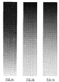
- Figures 1a, 1b and 1c show conventional round, square and "elliptical" dot patterns respectively, varying smoothly in size from about 10% print area density in light tones to about 90% area density in dark tones.
- Round dots have outwardly curved edges by definition whereas square or diamond shaped dots have flat edges between four points.
- the square patterns are invertible in that the printed areas in light tones have similar shapes to the non-printed areas in dark tones and vice versa.
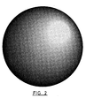
- Figure 2 demonstrates a more complicated dot pattern in which conventional round dots in light tones become square dots in middle tones with reversal of the round dots in dark tones. This is often referred to as the Euclidean dot pattern.
- the edge curvature of printed areas correspondingly changes from outward to flat to inward respectively. Moiré effects do not arise in Figures 1 and 2 as only a single screen is present in each case. Dot gain is not apparent due to the magnification.
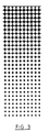
- Figure 3 shows a reversed round dot pattern varying uniformly from light to dark tones.
- the dots in light tones have inwardly curved edges between cusps distributed on two planes of mirror symmetry. Their points could perhaps be flattened or rounded as desired. Each dot meets its four nearest neighbours simultaneously at around 22% area density. Otherwise the inwards curvature extends along substantially the full length of all printed areas.
- the non-printed areas have corresponding outwardly curved edges and separate to appear as round dots in the dark tones.
- Overall the pattern is seen to be effectively a reversal or negative of the conventional round dot pattern in Figure 1a throughout the entire range of tones, and in this respect may be considered a pattern of light round dots on a dark printed background.
- Figures 4a and 4b show a reversed variable oval dot pattern suitable for use in the invention.
- the generally pin cushion shaped dots are elongated along a plane of mirror symmetry in light quarter to middle tones, so that nearest neighbours meet first vertically along the direction of tone darkening and then second horizontally in the corresponding perpendicular direction.
- Each dot meets two opposing pairs in two distinct stages of around 22% and 36% area density.
- This pattern is seen to be effectively a reversal or negative of a round dot pattern in which the dots become oval in middle tones.
- Figure 4a shows a full range of tone from 0% to 100% while Figure 4b shows more detail of the fourfold/twofold or alternatively the round/oval variation from about 15% to 39% area density. Rosette moiré effects can be reduced as with the pattern of Figure 3, but now by controlling dot elongation the perceptibility of any tone jumps can also be reduced by splitting dot gain into two less obvious stages which in turn may be shifted among a range of
- Figures 5a, 5b and 5c show example variations of dot edges suitable for use in the invention superimposed on common centres.
- the diagonally lined squares facilitate comparison and measurement in production.
- the edges are not necessarily mathematical ellipses but may take any suitable oval or approximately similar form as can be generated by computer.
- Figure 5a shows the gentle round-oval-round variation of Figures 4a and 4b.
- Figures 5b and 5c show more severe distortions resulting in greater separation of the dot gain stages.
- These figures are contour patterns which have been used in manual preparation of threshold matrices as described on pages 15 and 16 of the Seybold Report mentioned above.
- Figures 6a and 6b are an illustration of the reduction in rosette moiré effect which can be achieved.
- Figure 6a shows rosettes created by superimposing two conventional round dot screens at 30°, as is common with cyan and magenta in coloured images.
- Figure 6b shows a smoother variation of similar tones created by superimposing two reversed variable oval dot screens at 90° according to the invention. Preparing colored images using all four possible screens is less straightforward.
- the primary color screens are placed at 45° angular separations, such as cyan 45°, magenta 135° and yellow 90°, with black placed at 0° or 90°.
- the cyan and magenta screens use elongated dots of the reversed variable oval dot pattern, while yellow may use only the reversed round dot pattern. Black may only need the reversed round dot pattern, or may even give satisfactory images using the conventional round dot pattern itself.
- black dots are often not necessary in preparing a well defined colored image.
- the primary color screens may be used alone at the angles and with the patterns mentioned above.
- the cyan and magenta screens should be offset from each other to avoid possible color shifts.
- the offset should be about half a cell parallel with either of the screen directions, for best results in view of the accidental offsets which often occur during printing.
- Yellow and black screens should also sometimes be offset to avoid color shifts. The nature of these offsets has yet to be fully explored but will be evident to a skilled reader working on a particular image.
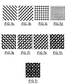
- Figures 7a to 7i show the dot patterns of a test which has been carried out to date according to the invention.
- Figures 7a to 7d represent individual screens of cyan 135°, magenta 45°, yellow 0° and black 0/90°, all at tone values where the printing and non-printing areas have linked with two or four of their nearest neighbours. Cyan and magenta use the reversed variable oval dot pattern. Yellow and black use simply the reversed round dot pattern. The black screen ruling has been reduced by a factor of about 0.71 relative to the others.
- Figures 7e to 7g show screens superimposed in pairs, namely cyan/yellow, magenta/yellow and cyan/magenta.
- Figures 8a to 8i show an attempt to contrast with figures 7a to 7i, the conventional round dot patterns which would typically have been used.
- Figures 8a to 8d represent individual screens of cyan 15°, magenta 45°, yellow 0° and black 75°.
- Figures 8e to 8g show these screens superimposed in pairs, namely cyan/yellow, magenta/yellow and cyan/magenta.
- Figure 8h shows the cyan, magenta and yellow screens superimposed.
- Figure 8i shows the black screen of figure 8d superimposed on figure 8h.
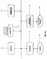
- FIG. 10 shows an exemplary block diagram of a high end computer controlled apparatus which is known from the prior art and can be used by a human operator in implementing the process of Figure 9.
- the operator interfaces with the apparatus through a keyboard or other appropriate hardware and software 140.
- a recorded scene 150 such as a photograph is passed under scanner 110 to produce pixel data. That data is then stored in a memory 130 which is typically a hard disc.
- a computer processor 100 is then used to select and modify dot patterns based on color and shading information in the pixel data.
- Halftone screens in primary colors and/or black are output through a printer or imagesetter 120, or may be output to a further memory device.
- the scenes are combined in preparation of a high quality halftone image 160.
Landscapes
- Engineering & Computer Science (AREA)
- Multimedia (AREA)
- Signal Processing (AREA)
- Physics & Mathematics (AREA)
- General Physics & Mathematics (AREA)
- Facsimile Image Signal Circuits (AREA)
- Color Image Communication Systems (AREA)
- Dot-Matrix Printers And Others (AREA)
- Color, Gradation (AREA)
- Image Generation (AREA)
- Image Processing (AREA)
Claims (28)
- Verfahren zur Herstellung von Halbtonrastern vor dem Drucken einer farbigen Abbildung mit den Stufen, in denen man(a) Information empfängt, welche Farbe und Tonabweichung in der Abbildung entspricht,(b) die Information unter Erzeugung von Halbtonrastern, welche primären Farben in der Abbildung entsprechen, verarbeitet, indem man1) Cyan- und Magente-Raster erzeugt, welche Druckbereiche mit einwärts gekrümmten Rändern aufweisen, und2) jedes primäre Farbraster in einem Winkel ausrichtet, welcher etwa ein Vielfaches von 45° zu jedem anderen primären Farbraster ist, und(c) Halbtonraster erzeugt, welche primären Farben in einer für anschließendes Drucken der farbigen Abbildung geeigneten Form entsprechen.
- Verfahren nach Anspruch 1, das weiterhin die Stufe umfaßt, in der mandie Cyan- und Magenta-Raster mit Druckbereichen in hellen Tönen, die als Punkte ausgebildet sind, welche zunehmend mit dunkler werdenden Tönen verlängert sind, erzeugt.
- Verfahren nach Anspruch 2, welches weiterhin umfaßt, daß man die Punkte in zwei verschiedenen Stufen miteinander verbindet, während der Ton dunkler wird.
- Verfahren nach Anspruch 1, welches weiterhin die Stufe umfaßt, in der mandie Cyan- und Magenta-Raster mit Nicht-Druckbereichen in dunklen Tönen, die als Punkte ausgebildet sind, welche zunehmend mit heller werdenden Tönen verlängert sind, erzeugt.
- Verfahren nach Anspruch 4, welches weiterhin umfaßt, daß man die Punkte in zwei verschiedenen Stufen miteinander verbindet, während der Ton heller wird.
- Verfahren nach Anspruch 1, welches weiterhin die Stufe umfaßt, in der manCyan- und Magenta-Raster erzeugt, die relativ zueinander versetzt sind.
- Verfahren nach Anspruch 1, welches weiterhin die Stufe umfaßt, in der manCyan- und Magenta-Raster mit Druckbereichen erzeugt, welche an jedem Rand in hellen Tönen einwärts gekrümmt sind.
- Verfahren nach Anspruch 1, welches weiterhin die Stufe umfaßt, in der manjedes primäre Farbraster mit Druckbereichen mit einwärts gekrümmten Rändern erzeugt.
- Verfahren nach Anspruch 1, welches weiterhin die Stufe umfaßt, in der manein schwarzes Raster mit Druckbereichen mit einwärts gekrümmten Rändern erzeugt.
- Verfahren nach Anspruch 9, welches weiterhin die Stufe umfaßt, in der mangelbe und schwarze Raster etwa 90° zueinander ausrichtet.
- Verfahren nach Anspruch 9, welches weiterhin die Stufe umfaßt, in der mandas schwarze Raster in einem Winkel ausrichtet, welcher etwa ein Vielfaches von 45° gegenüber jedem anderen Raster ist.
- Verfahren nach Anspruch 11, welches weiterhin die Stufe umfaßt, in der mandas schwarze Raster mit einer Rasterteilung erzeugt, welche gegenüber den Cyan- und Magenta-Rastern um einen Faktor von etwa 0,71 reduziert ist.
- Verfahren nach Anspruch 1, welches weiterhin die Stufe umfaßt, in der mandie Cyan- und Magenta-Raster etwa 90° zueinander ausrichtet.
- Verfahren zum Drucken von Halbtonrastern zur Erzeugung einer farbigen Abbildung mit den Stufen, in denen man(a) Information empfängt, welche Primärfarbenhalbtonrastern entspricht, worin Cyan- und Magenta-Raster Druckbereiche mit einwärts gekrümmten Rändern aufweisen,(b) jedes Primärfarbenraster in einem Winkel ausrichtet, welcher gegenüber jedem anderen Primärfarbenraster etwa ein Vielfaches von 45° ist, und(c) die ausgerichteten Primärfarbenraster zur Erzeugung einer farbigen Abbildung übereinander legt und druckt.
- Verfahren nach Anspruch 14, welches weiterhin die Stufen umfaßt, in denen manInformation empfängt, welche einem schwarzen Halbtonraster entspricht,das schwarze Halbtonraster in einem Winkel ausrichtet, welcher etwa ein Vielfaches von 45° gegenüber jedem anderen Raster ist, unddas ausgerichtete schwarze Farbraster mit den Primärfarbenrastern zur Erzeugung der farbigen Abbildung druckt.
- Computer gesteuerte Vorrichtung zur Erzeugung von Halbtonrastern, welche eine farbige Abbildung wiedergeben, mitMitteln zum Abtasten einer zuvor aufgezeichneten Szene zur Erzeugung von Information, welche Farbe und Tonvariation in der Szene entspricht,Mitteln zur Verarbeitung der Information zur Erzeugung von Halbtonrastern, welche den Primärfarben und der Schwarztonvariation in der Szene entsprechen, undMitteln zur Erzeugung der Halbtonraster in oder auf einem Ausgabemedium,
wobei die Mittel zur Verarbeitung Mittel zur Erzeugung von Cyan- und Magenta-Rastern, welche Druckbereiche mit einwärts gekrümmten Rändern haben, und Mittel zur Ausrichtung jedes Primärfarbenrasters in einem Winkel, welcher etwa ein Vielfaches von 45° gegenüber jedem anderen Primärfarbenraster ist, umfassen. - Vorrichtung nach Anspruch 16, wobei die Mittel zur Verarbeitung weiterhin Mittel zur Erzeugung von Tonvariation in den Primärfarbenhalbtonrastern durch Erzeugung von Druckbereichen, welche in Längsrichtung zwischen hallen und dunklen Tönen vartieren, umfassen.
- Vorrichtung nach Anspruch 16, wobei die Mittel zur Verarbeitung weiterhin Mittel zur Erzeugung von Tonvariation in den Primärfarbenhalbtonrastern durch Erzeugung von Nicht-Druckbereichen, welche in Längsrichtung zwischen dunklen und hellen Tönen variieren, umfassen.
- Computer gesteuerte Vorrichtung zur Erzeugung von Halbtonrastern, welche eine farbige Abbildung wiedergeben, mit(a) Mitteln zum Empfangen von Information, welche Farbe und Tonvariation in der Abbildung entspricht,(b) Mitteln zur Verarbeitung der Information zur Erzeugung von Halbtonrastern, welche Primärfarben in der Abbildung entsprechen, und(c) Mitteln zur Erzeugung von Halbtonrastern, welche Primärfarben in einer für anschließendes Drucken der Abbildung geeigneten Form entsprechen,
wobei die Mittel zur Verarbeitung Mittel zur Erzeugung von Cyan- und Magenta-Rastern, welche Druckbereiche mit einwärts gekrümmten Rändern haben, und Mittel zur Ausrichtung jedes Primärfarbenrasters in einem Winkel, welcher etwa ein Vielfaches von 45° gegenüber jedem anderen Primärfarbenraster ist, umfassen. - Vorrichtung nach Anspruch 19, wobei die Mittel zur Verarbeitung Mittel zur Erzeugung von Tonvariation in den Primärfarbenhalbtonrastern durch Erzeugung von Druckbereichen, welche in Längsrichtung zwischen hellen und dunklen Tönen variieren, umfassen.
- Vorrichtung nach Anspruch 20, wobei die Mittel zur Verarbeitung Mittel zur Verbindung der Druckbereiche in zwei verschiedenen Stufen, während der Ton dunkler bzw. heller wird, umfassen.
- Vorrichtung nach Anspruch 19, wobei die Mittel zur Verarbeitung Mittel zur Erzeugung von Tonvariation in den Primärfarbenhalbtonrastern durch Erzeugung von Nicht-Druckbereichen, welche in Längsrichtung zwischen dunklen und hellen Tönen variieren, umfassen.
- Vorrichtung nach Anspruch 22, wobei die Mittel zur Verarbeitung Mittel zur Verbindung der Nicht-Druckbereiche in zwei verschiedenen Stufen, während der Ton dunkler bzw. heller wird, umfassen.
- Verfahren zur Herstellung einer Halbtonabbildung, wobei eine Tonvariation in Cyan- und Magenta-Rastern durch die Stufen erzeugt wird, in denen manDruckbereiche erzeugt, welche einwärts gekrümmte Ränder haben, undjedes Primärfarbenraster in einem Winkel anordnet, welcher ein Vielfaches von etwa 45° gegenüber jedem anderen Primärfarbenraster ist.
- Halbtonabbildung, bei welcher Tonvariationen zumindest zum Teil durch gedruckte Bereiche erzeugt werden, welche einwärts gekrümmte Ränder haben und in welchen jedes Primärfarbenraster in einem Winkel ausgerichtet ist, welcher etwa ein Vielfaches von 45° gegenüber jedem anderen Primärfarbenraster ist.
- Abbildung nach Anspruch 25, in welcher eine Tonvariation in Cyan- und Magenta-Rastern erzeugt wird, indem man Bereiche in hellen Tönen druckt, die als Punkte ausgebildet sind, welche zunehmend zu dunkleren Tönen verlängert sind.
- Abbildung nach Anspruch 25, bei welcher Cyan- und Magenta-Raster etwa 90° zueinander ausgerichtet sind.
- Abbildung nach Anspruch 25, bei welcher Gelb- und Schwarz-Raster etwa 90° zueinander ausgerichtet sind.
Priority Applications (1)
| Application Number | Priority Date | Filing Date | Title |
|---|---|---|---|
| EP99124667A EP1005222A3 (de) | 1991-08-13 | 1992-08-13 | Halbtonrastermotive |
Applications Claiming Priority (8)
| Application Number | Priority Date | Filing Date | Title |
|---|---|---|---|
| NZ239389A NZ239389A (en) | 1991-08-13 | 1991-08-13 | Preparing half tone images: dots have inwardly curved edges |
| NZ239389 | 1991-08-13 | ||
| NZ240636 | 1991-11-18 | ||
| NZ24063691 | 1991-11-18 | ||
| NZ24097991 | 1991-12-13 | ||
| NZ240979 | 1991-12-13 | ||
| NZ24258392 | 1992-05-01 | ||
| NZ242583 | 1992-05-01 |
Related Child Applications (1)
| Application Number | Title | Priority Date | Filing Date |
|---|---|---|---|
| EP99124667A Division EP1005222A3 (de) | 1991-08-13 | 1992-08-13 | Halbtonrastermotive |
Publications (3)
| Publication Number | Publication Date |
|---|---|
| EP0527655A2 EP0527655A2 (de) | 1993-02-17 |
| EP0527655A3 EP0527655A3 (en) | 1995-09-06 |
| EP0527655B1 true EP0527655B1 (de) | 2000-11-02 |
Family
ID=27484315
Family Applications (1)
| Application Number | Title | Priority Date | Filing Date |
|---|---|---|---|
| EP92307424A Expired - Lifetime EP0527655B1 (de) | 1991-08-13 | 1992-08-13 | Halbtondruckmasken |
Country Status (6)
| Country | Link |
|---|---|
| EP (1) | EP0527655B1 (de) |
| JP (1) | JPH06205221A (de) |
| AT (1) | ATE197363T1 (de) |
| AU (1) | AU668868B2 (de) |
| CA (1) | CA2076085A1 (de) |
| DE (1) | DE69231544T2 (de) |
Cited By (4)
| Publication number | Priority date | Publication date | Assignee | Title |
|---|---|---|---|---|
| WO2013081480A1 (en) * | 2011-12-02 | 2013-06-06 | Megadot Systems Limited | Method and system for forming a halftone screen |
| WO2014102655A1 (en) * | 2012-12-24 | 2014-07-03 | Megadot Systems Limited | Method and system for forming a halftone screen |
| WO2025181133A1 (en) | 2024-02-27 | 2025-09-04 | Sicpa Holding Sa | Processes for producing optical effects layers |
| WO2025233239A1 (en) | 2024-05-08 | 2025-11-13 | Sicpa Holding Sa | Processes for producing optical effect layers |
Families Citing this family (6)
| Publication number | Priority date | Publication date | Assignee | Title |
|---|---|---|---|---|
| DE19633288C1 (de) * | 1996-08-19 | 1998-01-15 | Nationalzeitung Und Basler Nac | Raster an einer Druckeinheit beim Offsetdruckverfahren |
| DE19929902A1 (de) * | 1999-06-29 | 2001-01-04 | Sandy Screen Ag Zug | Form eines Druckelements beim Offset-Druckverfahren |
| DE19929904A1 (de) * | 1999-06-29 | 2001-01-04 | Sandy Screen Ag Zug | Form eines Druckelements beim Offset-Druckverfahren |
| DE19929901A1 (de) * | 1999-06-29 | 2001-01-04 | Sandy Screen Ag Zug | Form eines Druckelements beim Offset-Druckverfahren |
| CN108153936B (zh) * | 2017-12-01 | 2020-09-04 | Oppo广东移动通信有限公司 | 用于电子设备的渐变色工艺 |
| NL2023203B1 (en) * | 2019-05-27 | 2020-12-02 | Spgprints B V | Screen printing, in particular rotary screen printing of textile materials |
Family Cites Families (6)
| Publication number | Priority date | Publication date | Assignee | Title |
|---|---|---|---|---|
| SE348849B (de) * | 1969-05-27 | 1972-09-11 | A Jemseby | |
| US3966396A (en) * | 1974-12-18 | 1976-06-29 | F P Licensing Co Inc | Textile printing process and transfer medium |
| DE2917242C2 (de) * | 1979-04-27 | 1983-04-14 | Fogra Deutsche Forschungsgesellschaft für Druck- und Reproduktionstechnik e.V., 8000 München | Rasterpunktkontur |
| JPH0691621B2 (ja) * | 1988-11-24 | 1994-11-14 | 大日本スクリーン製造株式会社 | 網目版画像記録方法および装置 |
| JPH0741735B2 (ja) * | 1989-09-12 | 1995-05-10 | 東洋製罐株式会社 | 事前印刷成形体の製造法 |
| JPH03254987A (ja) * | 1990-03-05 | 1991-11-13 | Toppan Printing Co Ltd | 印刷物及び印刷物の作成方法 |
-
1992
- 1992-08-13 AT AT92307424T patent/ATE197363T1/de not_active IP Right Cessation
- 1992-08-13 AU AU21027/92A patent/AU668868B2/en not_active Ceased
- 1992-08-13 JP JP4258792A patent/JPH06205221A/ja active Pending
- 1992-08-13 CA CA002076085A patent/CA2076085A1/en not_active Abandoned
- 1992-08-13 DE DE69231544T patent/DE69231544T2/de not_active Expired - Fee Related
- 1992-08-13 EP EP92307424A patent/EP0527655B1/de not_active Expired - Lifetime
Cited By (6)
| Publication number | Priority date | Publication date | Assignee | Title |
|---|---|---|---|---|
| WO2013081480A1 (en) * | 2011-12-02 | 2013-06-06 | Megadot Systems Limited | Method and system for forming a halftone screen |
| US9208418B2 (en) | 2011-12-02 | 2015-12-08 | Megadot Systems Limited | Method and system for forming a halftone screen |
| WO2014102655A1 (en) * | 2012-12-24 | 2014-07-03 | Megadot Systems Limited | Method and system for forming a halftone screen |
| US9578205B2 (en) | 2012-12-24 | 2017-02-21 | Megadot Systems Limited | Method and system for forming a halftone screen |
| WO2025181133A1 (en) | 2024-02-27 | 2025-09-04 | Sicpa Holding Sa | Processes for producing optical effects layers |
| WO2025233239A1 (en) | 2024-05-08 | 2025-11-13 | Sicpa Holding Sa | Processes for producing optical effect layers |
Also Published As
| Publication number | Publication date |
|---|---|
| ATE197363T1 (de) | 2000-11-15 |
| CA2076085A1 (en) | 1993-02-14 |
| JPH06205221A (ja) | 1994-07-22 |
| AU668868B2 (en) | 1996-05-23 |
| DE69231544T2 (de) | 2001-03-15 |
| DE69231544D1 (de) | 2000-12-07 |
| EP0527655A2 (de) | 1993-02-17 |
| EP0527655A3 (en) | 1995-09-06 |
| AU2102792A (en) | 1993-02-18 |
Similar Documents
| Publication | Publication Date | Title |
|---|---|---|
| US6072592A (en) | Method and apparatus for preparing color screens in a halftone image | |
| US5680222A (en) | Method and apparatus for preparing color screens in a halftone image | |
| US5463471A (en) | Method and system of color halftone reproduction | |
| EP1107178A2 (de) | Gradientbassierte Verbesserung von Farbtrennflächen mit Hilfe von gemusterten Bereichen | |
| EP1180304B1 (de) | Verfahren und gerät zur kompensierung der punktvergrösserung beim stochastischen drucken | |
| EP0527655A2 (de) | Halbtonpunktmuster | |
| US7826097B2 (en) | Asymmetrical digital filters for dot gain adjustments | |
| CN108803251A (zh) | 一种凹印版辊的制版方法 | |
| CA2058027A1 (en) | Digital electronic system for halftone printing | |
| US7245400B2 (en) | Method and device for proofing raster print data while maintaining the raster information | |
| EP0581415A2 (de) | System und Verfahren zur rasterlosen Umsetzung mit grosser Genauigkeit unter Benutzung eines trennbaren Filters | |
| US5777757A (en) | Method and system for halftoning | |
| US7280259B2 (en) | Method for printing a color proof using a spatial filter | |
| US5841458A (en) | Halftoning method for multi-color laser printer | |
| US7050200B2 (en) | Lookup table for adjusting dot-gain on bitmap files based on average number of dots | |
| US6141121A (en) | Method and apparatus for color halftoning | |
| US7268920B1 (en) | Halftone patterns | |
| AU704935B2 (en) | Halftone printing area patterns | |
| US9578205B2 (en) | Method and system for forming a halftone screen | |
| NZ272570A (en) | Preparing half tone images: creating half tone dots with inwardly curved edges, and aligning primary colour screens at odd multiples of 45 degrees to each other | |
| JP2004291282A (ja) | グラビア印刷方法及びグラビア印刷物 | |
| JPH09237055A (ja) | 立体用又は可変用印刷物 | |
| US20050030329A1 (en) | Method for adjusting dot-gain for a halftone binary bitmap | |
| Kuznetsov | HALFTONING MYTHS AND REALITY. WHAT IS ADAPTIVE TO WHAT IN SCREENING? | |
| JP2001088422A (ja) | 印刷方法 |
Legal Events
| Date | Code | Title | Description |
|---|---|---|---|
| PUAI | Public reference made under article 153(3) epc to a published international application that has entered the european phase |
Free format text: ORIGINAL CODE: 0009012 |
|
| AK | Designated contracting states |
Kind code of ref document: A2 Designated state(s): AT BE CH DE DK ES FR GB GR IE IT LI LU NL PT SE |
|
| PUAL | Search report despatched |
Free format text: ORIGINAL CODE: 0009013 |
|
| AK | Designated contracting states |
Kind code of ref document: A3 Designated state(s): AT BE CH DE DK ES FR GB GR IE IT LI LU NL PT SE |
|
| 17P | Request for examination filed |
Effective date: 19960304 |
|
| 17Q | First examination report despatched |
Effective date: 19971031 |
|
| GRAG | Despatch of communication of intention to grant |
Free format text: ORIGINAL CODE: EPIDOS AGRA |
|
| GRAG | Despatch of communication of intention to grant |
Free format text: ORIGINAL CODE: EPIDOS AGRA |
|
| GRAG | Despatch of communication of intention to grant |
Free format text: ORIGINAL CODE: EPIDOS AGRA |
|
| GRAH | Despatch of communication of intention to grant a patent |
Free format text: ORIGINAL CODE: EPIDOS IGRA |
|
| GRAH | Despatch of communication of intention to grant a patent |
Free format text: ORIGINAL CODE: EPIDOS IGRA |
|
| GRAA | (expected) grant |
Free format text: ORIGINAL CODE: 0009210 |
|
| AK | Designated contracting states |
Kind code of ref document: B1 Designated state(s): AT BE CH DE DK ES FR GB GR IE IT LI LU NL PT SE |
|
| PG25 | Lapsed in a contracting state [announced via postgrant information from national office to epo] |
Ref country code: NL Free format text: LAPSE BECAUSE OF FAILURE TO SUBMIT A TRANSLATION OF THE DESCRIPTION OR TO PAY THE FEE WITHIN THE PRESCRIBED TIME-LIMIT Effective date: 20001102 Ref country code: LI Free format text: LAPSE BECAUSE OF FAILURE TO SUBMIT A TRANSLATION OF THE DESCRIPTION OR TO PAY THE FEE WITHIN THE PRESCRIBED TIME-LIMIT Effective date: 20001102 Ref country code: IT Free format text: LAPSE BECAUSE OF FAILURE TO SUBMIT A TRANSLATION OF THE DESCRIPTION OR TO PAY THE FEE WITHIN THE PRESCRIBED TIME-LIMIT;WARNING: LAPSES OF ITALIAN PATENTS WITH EFFECTIVE DATE BEFORE 2007 MAY HAVE OCCURRED AT ANY TIME BEFORE 2007. THE CORRECT EFFECTIVE DATE MAY BE DIFFERENT FROM THE ONE RECORDED. Effective date: 20001102 Ref country code: GR Free format text: LAPSE BECAUSE OF NON-PAYMENT OF DUE FEES Effective date: 20001102 Ref country code: ES Free format text: THE PATENT HAS BEEN ANNULLED BY A DECISION OF A NATIONAL AUTHORITY Effective date: 20001102 Ref country code: CH Free format text: LAPSE BECAUSE OF FAILURE TO SUBMIT A TRANSLATION OF THE DESCRIPTION OR TO PAY THE FEE WITHIN THE PRESCRIBED TIME-LIMIT Effective date: 20001102 Ref country code: BE Free format text: LAPSE BECAUSE OF FAILURE TO SUBMIT A TRANSLATION OF THE DESCRIPTION OR TO PAY THE FEE WITHIN THE PRESCRIBED TIME-LIMIT Effective date: 20001102 Ref country code: AT Free format text: LAPSE BECAUSE OF FAILURE TO SUBMIT A TRANSLATION OF THE DESCRIPTION OR TO PAY THE FEE WITHIN THE PRESCRIBED TIME-LIMIT Effective date: 20001102 |
|
| REF | Corresponds to: |
Ref document number: 197363 Country of ref document: AT Date of ref document: 20001115 Kind code of ref document: T |
|
| RTI1 | Title (correction) |
Free format text: HALFTONE PRINTING SCREENS |
|
| REG | Reference to a national code |
Ref country code: CH Ref legal event code: EP |
|
| REF | Corresponds to: |
Ref document number: 69231544 Country of ref document: DE Date of ref document: 20001207 |
|
| REG | Reference to a national code |
Ref country code: IE Ref legal event code: FG4D |
|
| ET | Fr: translation filed | ||
| PG25 | Lapsed in a contracting state [announced via postgrant information from national office to epo] |
Ref country code: SE Free format text: LAPSE BECAUSE OF FAILURE TO SUBMIT A TRANSLATION OF THE DESCRIPTION OR TO PAY THE FEE WITHIN THE PRESCRIBED TIME-LIMIT Effective date: 20010202 Ref country code: PT Free format text: LAPSE BECAUSE OF FAILURE TO SUBMIT A TRANSLATION OF THE DESCRIPTION OR TO PAY THE FEE WITHIN THE PRESCRIBED TIME-LIMIT Effective date: 20010202 Ref country code: DK Free format text: LAPSE BECAUSE OF FAILURE TO SUBMIT A TRANSLATION OF THE DESCRIPTION OR TO PAY THE FEE WITHIN THE PRESCRIBED TIME-LIMIT Effective date: 20010202 |
|
| NLV1 | Nl: lapsed or annulled due to failure to fulfill the requirements of art. 29p and 29m of the patents act | ||
| REG | Reference to a national code |
Ref country code: CH Ref legal event code: PL |
|
| PG25 | Lapsed in a contracting state [announced via postgrant information from national office to epo] |
Ref country code: LU Free format text: LAPSE BECAUSE OF NON-PAYMENT OF DUE FEES Effective date: 20010813 Ref country code: IE Free format text: LAPSE BECAUSE OF NON-PAYMENT OF DUE FEES Effective date: 20010813 |
|
| PLBE | No opposition filed within time limit |
Free format text: ORIGINAL CODE: 0009261 |
|
| STAA | Information on the status of an ep patent application or granted ep patent |
Free format text: STATUS: NO OPPOSITION FILED WITHIN TIME LIMIT |
|
| 26N | No opposition filed | ||
| REG | Reference to a national code |
Ref country code: GB Ref legal event code: IF02 |
|
| REG | Reference to a national code |
Ref country code: IE Ref legal event code: MM4A |
|
| PGFP | Annual fee paid to national office [announced via postgrant information from national office to epo] |
Ref country code: GB Payment date: 20030812 Year of fee payment: 12 |
|
| PGFP | Annual fee paid to national office [announced via postgrant information from national office to epo] |
Ref country code: FR Payment date: 20030814 Year of fee payment: 12 |
|
| PG25 | Lapsed in a contracting state [announced via postgrant information from national office to epo] |
Ref country code: GB Free format text: LAPSE BECAUSE OF NON-PAYMENT OF DUE FEES Effective date: 20040813 |
|
| PGFP | Annual fee paid to national office [announced via postgrant information from national office to epo] |
Ref country code: DE Payment date: 20050222 Year of fee payment: 13 |
|
| GBPC | Gb: european patent ceased through non-payment of renewal fee |
Effective date: 20040813 |
|
| PG25 | Lapsed in a contracting state [announced via postgrant information from national office to epo] |
Ref country code: FR Free format text: LAPSE BECAUSE OF NON-PAYMENT OF DUE FEES Effective date: 20050429 |
|
| REG | Reference to a national code |
Ref country code: FR Ref legal event code: ST |
|
| PG25 | Lapsed in a contracting state [announced via postgrant information from national office to epo] |
Ref country code: DE Free format text: LAPSE BECAUSE OF NON-PAYMENT OF DUE FEES Effective date: 20060301 |