EP0527862B1 - Kraft- oder druckvergrössernde vorrichtung - Google Patents
Kraft- oder druckvergrössernde vorrichtung Download PDFInfo
- Publication number
- EP0527862B1 EP0527862B1 EP91909179A EP91909179A EP0527862B1 EP 0527862 B1 EP0527862 B1 EP 0527862B1 EP 91909179 A EP91909179 A EP 91909179A EP 91909179 A EP91909179 A EP 91909179A EP 0527862 B1 EP0527862 B1 EP 0527862B1
- Authority
- EP
- European Patent Office
- Prior art keywords
- valve
- valve body
- channel
- master cylinder
- fluid
- Prior art date
- Legal status (The legal status is an assumption and is not a legal conclusion. Google has not performed a legal analysis and makes no representation as to the accuracy of the status listed.)
- Expired - Lifetime
Links
Images

Classifications
-
- B—PERFORMING OPERATIONS; TRANSPORTING
- B60—VEHICLES IN GENERAL
- B60T—VEHICLE BRAKE CONTROL SYSTEMS OR PARTS THEREOF; BRAKE CONTROL SYSTEMS OR PARTS THEREOF, IN GENERAL; ARRANGEMENT OF BRAKING ELEMENTS ON VEHICLES IN GENERAL; PORTABLE DEVICES FOR PREVENTING UNWANTED MOVEMENT OF VEHICLES; VEHICLE MODIFICATIONS TO FACILITATE COOLING OF BRAKES
- B60T11/00—Transmitting braking action from initiating means to ultimate brake actuator without power assistance or drive or where such assistance or drive is irrelevant
- B60T11/10—Transmitting braking action from initiating means to ultimate brake actuator without power assistance or drive or where such assistance or drive is irrelevant transmitting by fluid means, e.g. hydraulic
- B60T11/16—Master control, e.g. master cylinders
- B60T11/224—Master control, e.g. master cylinders with pressure-varying means, e.g. with two stage operation provided by use of different piston diameters including continuous variation from one diameter to another
-
- F—MECHANICAL ENGINEERING; LIGHTING; HEATING; WEAPONS; BLASTING
- F16—ENGINEERING ELEMENTS AND UNITS; GENERAL MEASURES FOR PRODUCING AND MAINTAINING EFFECTIVE FUNCTIONING OF MACHINES OR INSTALLATIONS; THERMAL INSULATION IN GENERAL
- F16D—COUPLINGS FOR TRANSMITTING ROTATION; CLUTCHES; BRAKES
- F16D25/00—Fluid-actuated clutches
- F16D25/12—Details not specific to one of the before-mentioned types
- F16D25/14—Fluid pressure control
-
- F—MECHANICAL ENGINEERING; LIGHTING; HEATING; WEAPONS; BLASTING
- F16—ENGINEERING ELEMENTS AND UNITS; GENERAL MEASURES FOR PRODUCING AND MAINTAINING EFFECTIVE FUNCTIONING OF MACHINES OR INSTALLATIONS; THERMAL INSULATION IN GENERAL
- F16D—COUPLINGS FOR TRANSMITTING ROTATION; CLUTCHES; BRAKES
- F16D48/00—External control of clutches
- F16D48/02—Control by fluid pressure
-
- F—MECHANICAL ENGINEERING; LIGHTING; HEATING; WEAPONS; BLASTING
- F16—ENGINEERING ELEMENTS AND UNITS; GENERAL MEASURES FOR PRODUCING AND MAINTAINING EFFECTIVE FUNCTIONING OF MACHINES OR INSTALLATIONS; THERMAL INSULATION IN GENERAL
- F16D—COUPLINGS FOR TRANSMITTING ROTATION; CLUTCHES; BRAKES
- F16D48/00—External control of clutches
- F16D48/02—Control by fluid pressure
- F16D48/04—Control by fluid pressure providing power assistance
-
- F—MECHANICAL ENGINEERING; LIGHTING; HEATING; WEAPONS; BLASTING
- F16—ENGINEERING ELEMENTS AND UNITS; GENERAL MEASURES FOR PRODUCING AND MAINTAINING EFFECTIVE FUNCTIONING OF MACHINES OR INSTALLATIONS; THERMAL INSULATION IN GENERAL
- F16D—COUPLINGS FOR TRANSMITTING ROTATION; CLUTCHES; BRAKES
- F16D48/00—External control of clutches
- F16D48/02—Control by fluid pressure
- F16D2048/0209—Control by fluid pressure characterised by fluid valves having control pistons, e.g. spools
-
- F—MECHANICAL ENGINEERING; LIGHTING; HEATING; WEAPONS; BLASTING
- F16—ENGINEERING ELEMENTS AND UNITS; GENERAL MEASURES FOR PRODUCING AND MAINTAINING EFFECTIVE FUNCTIONING OF MACHINES OR INSTALLATIONS; THERMAL INSULATION IN GENERAL
- F16D—COUPLINGS FOR TRANSMITTING ROTATION; CLUTCHES; BRAKES
- F16D48/00—External control of clutches
- F16D48/02—Control by fluid pressure
- F16D2048/0221—Valves for clutch control systems; Details thereof
Definitions
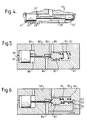
- a first passage or channel 25 connects the first end section 3 of the working cylinder bore 2 with a first end section of the valve bore 20, situated at the first end section 22 of the valve body.
- a connection passage or channel 27 connects the channel 25 to a clutch master cylinder or master cylinder (not shown), which via a clutch pedal mechanism can be operated by the vehicle's driver in a per se known manner.
- a channel 26 connects the working cylinder space 31 with the valve bore space 32.
- a shoulder which is constituted by for instance a safety ring 41 inserted in an annular groove and which forms a stopper against which the first end section 22 of the valve body 21 can be placed, and in the opposite or second end section of the bore 20 is arranged a spring device, e.g. a helical spring 30, which attempts to move the valve unit against the safety ring 41.
- a spring device e.g. a helical spring 30, which attempts to move the valve unit against the safety ring 41.
- in the housing can be installed a channel 42 which provides communication between the channel 26 and the latter end section of the bore 20.
- the fluid in channel 25 and the clutch master cylinder can be of the same type as the pressure fluid supplied from the pressure fluid source, or these fluids can be different, the fluid in channel 25 possibly being hydraulic oil and the fluid in channel 26 possibly being compressed air. If the fluid in channel 26 is compressed air, the clutch-servo can be simplified, since the return channel 29 can flow out into the open air.
- the release force required in ordinary clutch devices will vary depending on production tolerances and hysteresis in the clutch unit.
- the clutch-servo according to the invention can reduce such variations in force to a minimum.
Landscapes
- Engineering & Computer Science (AREA)
- General Engineering & Computer Science (AREA)
- Mechanical Engineering (AREA)
- Physics & Mathematics (AREA)
- Fluid Mechanics (AREA)
- Transportation (AREA)
- Hydraulic Clutches, Magnetic Clutches, Fluid Clutches, And Fluid Joints (AREA)
- Arrangement And Mounting Of Devices That Control Transmission Of Motive Force (AREA)
- Agricultural Machines (AREA)
- Fluid-Pressure Circuits (AREA)
- Earth Drilling (AREA)
- Steering Control In Accordance With Driving Conditions (AREA)
Claims (13)
- Kraft- oder Druckerhöhungsvorrichtung wie etwa eine Kupplungshilfskraftvorrichtung zum Ein- und Ausrücken von Fahrzeugkupplungen, wobei die Vorrichtung eine Arbeits- oder Nebenvorrichtung bildet, die zur Fluidverbindung mit einem von dem Fahrer des Fahrzeugs zu betätigenden Hauptzylinder angeordnet ist und folgendes aufweist: eine Arbeitszylindereinheit (50), die einen Kolben (5) hat, der in einen Arbeitszylinder, ein Gehäuse (1) oder eine ähnliche Anordnung eingebaut ist, wobei der Kolben mit der Einheit verbunden ist, die von der Kraft- oder Druckerhöhungsvorrichtung zu betätigen ist, und eine Steuerventileinheit (60) für den Arbeitszylinder (50) mit einem Ventilkörper (21, 21'), der in ein Ventilgehäuse (44) mit einem Zuführkanal (28, 28') und einem Rückführkanal (29, 29') für ein Servodruckfluid eingebaut ist, wobei der Hauptzylinder eine Fluidverbindung mit der Arbeitszylindereinheit (50) und der Steuerventileinheit (60) hat, so daß das Fluid von dem Hauptzylinder gleichzeitig eine Kraft auf den Kolben (5) und auf den Ventilkörper (21) aufbringt, um zu versuchen, den Kolben (5) bzw. den Ventilkörper (21) zu bewegen, wenn der Fahrer den Hauptzylinder betätigt, und der Ventilkörper (21) angeordnet ist, um eine Verbindung zwischen dem Zylinderraum (31) des Arbeitszylinders und dem Rückführkanal (29) für das Servodruckfluid herzustellen, wenn der Hauptzylinder außer Betrieb ist, wobei keine funktionsmäßig bestimmte mechanische Verbindung zwischen der Arbeitszylindereinheit und der Ventileinheit (60) besteht,
dadurch gekennzeichnet, daß die Ventileinheit (60) einen Schieber aufweist, wobei der Ventilkörper (21) auf an sich bekannte Weise in einer Bohrung (20) in Axialrichtung bewegbar ist und einen ersten bzw. einen zweiten Endabschnitt (22) bzw. (23) aufweist, dessen Durchmesser ausgebildet ist, um zu dem Durchmesser von zugehörigen Bohrungsabschnitten der Bohrung (20) zu passen, wobei die Endabschnitte über einen Schaftabschnitt (24) miteinander verbunden sind, dessen Durchmesser kleiner als der Durchmesser der Endabschnitte (22, 23) ist, so daß die Bohrung (20), die Endabschnitte (22, 23) und der Schaftabschnitt (24) einen Ventilraum (32) definieren, wobei das äußere Ende des ersten Endabschnitts (22), gerechnet in der Längsrichtung, angeordnet ist, um von dem Fluid von dem Hauptzylinder betätigt zu werden und an einer Schulter (41, 41') des Ventilgehäuses anzuliegen, eine Rückführeinrichtung (30, 42) versucht, den Ventilkörper (21) gegen die Schulter (41) zu bewegen, und der Rückführkanal (29) und der Zuführkanal (28) für Servofluid neben dem ersten bzw. dem zweiten Endabschnitt (22 bzw. 23) des Ventilkörpers (21) angeordnet sind, und in das Ventilgehäuse (44) ferner ein Verbindungskanal (26) eingebaut ist, so daß der Arbeitszylinderraum (31) mit dem Ventilraum (32) verbunden werden kann, der seinerseits mit dem Rückführkanal (29) verbunden ist, wenn der Ventilkörper (21) an der Schulter (41) anliegt. - Vorrichtung nach Anspruch 1,
dadurch gekennzeichnet, daß der Zuführkanal (28') während des Gesamthubs des Ventilkörpers (21') mit dem Zylinderraum (31) des Arbeitszylinders verbunden ist und daß der erste Endabschnitt (22') des Ventilkörpers angeordnet ist, um den Rückführkanal (29') allmählich zunehmend zu drosseln, wenn der Ventilkörper von der Schulter (41') wegbewegt wird. - Vorrichtung nach Anspruch 1,
dadurch gekennzeichnet, daß der erste Endabschnitt (22) des Ventilkörpers (21) angeordnet ist, um eine Verbindung zwischen dem Verbindungskanal (26) und dem Rückführkanal (29) zuzulassen, und der zweite Endabschnitt (23) des Ventilkörpers (21) angeordnet ist, um den Zuführkanal (28) zu schließen, wenn der Ventilkörper an der Schulter (41) anliegt, und der erste Endabschnitt (22) angeordnet ist, um den Rückführkanal zu schließen, und der zweite Endabschnitt (23) angeordnet ist, um den Zuführkanal (28) zu öffnen, wenn der Ventilkörper (21) von der Schulter (41) wegbewegt wird. - Vorrichtung nach einem der vorhergehenden Ansprüche,
dadurch gekennzeichnet, daß die Rückführeinrichtung von einer Druckfeder (30) gebildet ist, die zwischen dem äußeren Ende des zweiten Endabschnitt (23) des Ventilkörpers (21), gerechnet in der Längsrichtung des Ventilkörpers, und dem entgegengesetzten Ende der Bohrung (20) angeordnet ist. - Vorrichtung nach einem der Ansprüche 1-3,
dadurch gekennzeichnet, daß die Rückführeinrichtung einen Kanal (42) aufweist, der in dem Ventilgehäuse gebildet ist und der eine Verbindung zwischen dem Kanal (26), durch den der Arbeitszylinderraum (31) mit dem Ventilraum (32) verbunden werden kann, und dem Abschnitt der Bohrung (20) herstellt, der dem äußeren Ende des zweiten Endabschnitts (23) des Ventilkörpers (21) gegenüberliegt. - Vorrichtung nach einem der vorhergehenden Ansprüche,
dadurch gekennzeichnet, daß die Längsachse des Zuführkanals (28) und des Rückführkanals (29) senkrecht zu der Längsachse der Ventilbohrung (20) verläuft. - Vorrichtung nach einem der vorhergehenden Ansprüche,
dadurch gekennzeichnet, daß der Durchmesser des Zuführkanals (28) und des Rückführkanals (29) größer als der Durchmesser der benachbarten Abschnitte der Ventilbohrung (20) ist. - Kanal nach Anspruch 6 oder 7,
dadurch gekennzeichnet, daß der Rückführkanal (29) und der Zuführkanal (28) zu beiden Seiten der Bohrung (20) verlaufen. - Vorrichtung nach einem der vorhergehenden Ansprüche,
dadurch gekennzeichnet, daß ein Absperrventil (80, 100) in die Zuführleitung zwischen der Servodruckfluidquelle und dem Zuführkanal (28) eingebaut ist. - Vorrichtung nach Anspruch 9,
dadurch gekennzeichnet, daß das Absperrventil (80, 100) einen Ventilkörper (82) hat, der angeordnet ist, um das Ventil zu schließen, indem er in Anlage an einen Ventilsitz gebracht wird, und daß das Absperrventil (80, 100) mit einem Hauptzylinder derart verbunden ist, daß der Ventilkörper (82) von seinem Sitz wegbewegt wird und das Ventil öffnet, wenn der Hauptzylinder betätigt wird. - Vorrichtung nach Anspruch 10,
dadurch gekennzeichnet, daß der Ventilkörper (82) des Absperrventils in seiner Bewegungsrichtung hydrostatisch abgeglichen ist, wobei in dem Ventilgehäuse (101) ein Kanal (104) gebildet ist, der Zuführfluid auch zu der dem Sitz abgewandten Seite des Ventilkörpers (82) leitet. - Vorrichtung nach Anspruch 1,
dadurch gekennzeichnet, daß das Absperrventil (80, 100) eine Arbeitszylindereinheit mit einem Kolben (87) aufweist, der mit dem Ventilkörper (82) verbunden ist, wobei eine Seite des Kolbens (87) angeordnet ist, um von dem Druck des Fluids von dem Hauptzylinder betätigt zu werden und dadurch auf den Ventilkörper (82) eine Kraft aufzubringen, um ihn von seinem Sitz wegzubewegen. - Vorrichtung nach Anspruch 11,
dadurch gekennzeichnet, daß das Absperrventil ein elektrisches Relais aufweist und der Hauptzylinder angeordnet ist, um einen Schalter zu betätigen, der in einer elektrischen Schaltung enthalten ist, die angeordnet ist, um eine Magnetisierung des Relais zu bewirken und dadurch den Ventilkörper von seinem Sitz wegzubewegen und das Absperrventil zu öffnen, wenn der Hauptzylinder und dadurch der Schalter betätigt wird.
Applications Claiming Priority (3)
| Application Number | Priority Date | Filing Date | Title |
|---|---|---|---|
| NO902057 | 1990-05-09 | ||
| NO90902057A NO902057L (no) | 1990-05-09 | 1990-05-09 | Kraftforsterkningsinnretning til inn- og utkobling av kjoeretoeyclutcher. |
| PCT/NO1991/000068 WO1991017372A1 (en) | 1990-05-09 | 1991-05-08 | Force or pressure augmenting device |
Publications (2)
| Publication Number | Publication Date |
|---|---|
| EP0527862A1 EP0527862A1 (de) | 1993-02-24 |
| EP0527862B1 true EP0527862B1 (de) | 1994-08-24 |
Family
ID=19893151
Family Applications (1)
| Application Number | Title | Priority Date | Filing Date |
|---|---|---|---|
| EP91909179A Expired - Lifetime EP0527862B1 (de) | 1990-05-09 | 1991-05-08 | Kraft- oder druckvergrössernde vorrichtung |
Country Status (7)
| Country | Link |
|---|---|
| US (1) | US5337564A (de) |
| EP (1) | EP0527862B1 (de) |
| JP (1) | JP2825347B2 (de) |
| AT (1) | ATE110447T1 (de) |
| DE (1) | DE69103628T2 (de) |
| NO (1) | NO902057L (de) |
| WO (1) | WO1991017372A1 (de) |
Cited By (1)
| Publication number | Priority date | Publication date | Assignee | Title |
|---|---|---|---|---|
| US7404292B2 (en) | 2004-09-11 | 2008-07-29 | Luk Lamellen Und Kupplungsbau Beteiligungs Kg | Hydraulic system, in particular for motor vehicles |
Families Citing this family (10)
| Publication number | Priority date | Publication date | Assignee | Title |
|---|---|---|---|---|
| SE470517B (sv) * | 1992-11-06 | 1994-06-27 | Saab Scania Ab | Anordning för slitagevarning vid ett kopplingsservo för en lamellkoppling i en transmission |
| DE4441098C2 (de) * | 1994-11-18 | 1996-09-26 | Porsche Ag | Fremdkraftunterstützte Betätigungsvorrichtung |
| DE102005001861A1 (de) * | 2005-01-14 | 2006-07-27 | Dr.Ing.H.C. F. Porsche Ag | Hydraulische Kupplungsbetätigung für ein Kraftfahrzeug |
| FR2898952B1 (fr) * | 2006-03-21 | 2008-07-04 | Peugeot Citroen Automobiles Sa | Systeme d'assistance a l'embrayage et vehicule automobile comportant un tel systeme |
| US9651138B2 (en) | 2011-09-30 | 2017-05-16 | Mtd Products Inc. | Speed control assembly for a self-propelled walk-behind lawn mower |
| CN105008749B (zh) * | 2013-02-26 | 2018-09-25 | 博格华纳瑞典公司 | 一种操作awd车辆中液压盘式离合器的方法和离合器 |
| DE102013221035A1 (de) * | 2013-10-17 | 2015-04-23 | Zf Friedrichshafen Ag | Hydraulische Steuerungsvorrichtung für ein Automatikgetriebe |
| EP3066355A1 (de) * | 2013-11-05 | 2016-09-14 | Schaeffler Technologies AG & Co. KG | Hydraulikanordnung |
| DE102014216580A1 (de) * | 2014-08-21 | 2016-02-25 | Zf Friedrichshafen Ag | Hydraulische Steuerungsvorrichtung für ein Automatikgetriebe |
| CA3023021C (en) * | 2016-05-04 | 2020-12-29 | Ginda New-Tech Co., Ltd. | Hydraulic brake device with a time difference and assembly thereof |
Family Cites Families (17)
| Publication number | Priority date | Publication date | Assignee | Title |
|---|---|---|---|---|
| US2328637A (en) * | 1941-05-02 | 1943-09-07 | Wagner Electric Corp | Brake actuating system |
| US2467273A (en) * | 1941-06-13 | 1949-04-12 | Edward A Rockwell | Power apparatus with travel control |
| FR1043696A (fr) * | 1951-10-10 | 1953-11-10 | Westinghouse Freins & Signaux | Servo-frein hydropneumatique |
| IT536657A (de) * | 1954-06-05 | |||
| US2879645A (en) * | 1957-04-22 | 1959-03-31 | Kelsey Hayes Co | Booster brake mechanism |
| FR1251653A (fr) * | 1960-03-18 | 1961-01-20 | Dispositif correcteur de déphasage pour servo-frein oléopneumatique | |
| US3182443A (en) * | 1962-06-21 | 1965-05-11 | Dana Corp | Operating mechanism including an assist device |
| DE2124948C3 (de) * | 1971-05-19 | 1975-09-25 | Wabco Westinghouse Gmbh, 3000 Hannover | Selbsttätige Nachstellvorrichtung für eine hydraulische Kupplungsbetätigungseinrichtung eines Kraftfahrzeuges, insbesondere für einen hydropneumatischen Kupplungsverstärker |
| DE2440039C2 (de) * | 1974-08-21 | 1983-07-14 | Robert Bosch Gmbh, 7000 Stuttgart | Steuereinrichtung für die Kupplung eines Kraftfahrzeugs |
| FR2402564A1 (fr) * | 1977-09-09 | 1979-04-06 | Ferodo Sa | Commande hydraulique notamment pour dispositif de freinage de vehicule automobile |
| FR2480371A1 (fr) * | 1980-04-15 | 1981-10-16 | Ferodo Sa | Commande hydraulique assistee, notamment pour embrayages et freins |
| DE3031262C2 (de) * | 1980-08-19 | 1983-01-20 | Zahnradfabrik Friedrichshafen Ag, 7990 Friedrichshafen | Hydraulische Einrichtung zum gesteuerten/geregelten Druckverlauf in Kupplungen oder Bremsen |
| US4494377A (en) * | 1983-08-12 | 1985-01-22 | Yasuo Sato | Brake booster operated also by solenoid |
| DE3709166C1 (de) * | 1987-03-20 | 1988-09-22 | Knorr Bremse Ag | Hydropneumatischer Kupplungsverstaerker fuer Kraftfahrzeuge |
| GB8712779D0 (en) * | 1987-06-01 | 1987-07-08 | Alpha Kem Ltd | Lintel |
| EP0310733B1 (de) * | 1987-10-07 | 1990-09-05 | BENDIX ITALIA S.p.A. | Hydropneumatischer Betätiger für Kraftfahrzeuge |
| JP2740221B2 (ja) * | 1988-12-28 | 1998-04-15 | 曙ブレーキ工業株式会社 | ブレーキ液圧制御装置 |
-
1990
- 1990-05-09 NO NO90902057A patent/NO902057L/no unknown
-
1991
- 1991-05-08 US US07/940,905 patent/US5337564A/en not_active Expired - Lifetime
- 1991-05-08 WO PCT/NO1991/000068 patent/WO1991017372A1/en not_active Ceased
- 1991-05-08 DE DE69103628T patent/DE69103628T2/de not_active Expired - Fee Related
- 1991-05-08 JP JP3508974A patent/JP2825347B2/ja not_active Expired - Fee Related
- 1991-05-08 EP EP91909179A patent/EP0527862B1/de not_active Expired - Lifetime
- 1991-05-08 AT AT91909179T patent/ATE110447T1/de not_active IP Right Cessation
Cited By (1)
| Publication number | Priority date | Publication date | Assignee | Title |
|---|---|---|---|---|
| US7404292B2 (en) | 2004-09-11 | 2008-07-29 | Luk Lamellen Und Kupplungsbau Beteiligungs Kg | Hydraulic system, in particular for motor vehicles |
Also Published As
| Publication number | Publication date |
|---|---|
| US5337564A (en) | 1994-08-16 |
| ATE110447T1 (de) | 1994-09-15 |
| DE69103628D1 (de) | 1994-09-29 |
| JP2825347B2 (ja) | 1998-11-18 |
| NO902057L (no) | 1991-11-11 |
| WO1991017372A1 (en) | 1991-11-14 |
| DE69103628T2 (de) | 1995-04-13 |
| JPH06500845A (ja) | 1994-01-27 |
| EP0527862A1 (de) | 1993-02-24 |
| NO902057D0 (no) | 1990-05-09 |
Similar Documents
| Publication | Publication Date | Title |
|---|---|---|
| US5337564A (en) | Force or pressure augmenting device | |
| US4289221A (en) | Hydraulic control system | |
| JPS643701B2 (de) | ||
| US4130990A (en) | Hydraulic system for feeding a plurality of independent hydraulic servo-operated devices | |
| JPH04277326A (ja) | 特に自動車用の、ダイヤフラムスプリングを有する摩擦型クラッチを制御するためのアクチュエータ | |
| US4354584A (en) | Transmission-clutch operating system | |
| JP2744829B2 (ja) | ダイアフラムばねを有する流体圧作動摩擦ディスククラッチを制御する装置 | |
| US4014171A (en) | Hydraulic brake booster | |
| EP0802356B1 (de) | Elektrohydraulische Einrichtung zum Schalten eines servobetätigten Schaltgetriebes | |
| US5179835A (en) | Brake valve for use in load sensing hydraulic system | |
| US6679056B2 (en) | Pressure booster | |
| GB2077869A (en) | Brake system for an automotive vehicle | |
| JPH0514671B2 (de) | ||
| KR101117372B1 (ko) | 마스터 실린더 및 덤프 밸브의 조립체 | |
| US4007665A (en) | Brake booster with improved pedal feel characteristics | |
| US3703079A (en) | Hydraulic actuating systems | |
| JPS607125B2 (ja) | 液圧↓−空気圧式クラツチ制御装置 | |
| US4729223A (en) | Full power hydraulic assistance device | |
| US5193345A (en) | Distributor of a fluid under pressure | |
| US3032992A (en) | Power hydraulic brake device | |
| JPH0671878B2 (ja) | 一次圧力バランス比例弁 | |
| CA1100846A (en) | Multi-function steering and brake control valve | |
| AU598262B2 (en) | Hydraulic booster device | |
| US5114215A (en) | Brake system | |
| GB2074681A (en) | Brake master cylinder including proportioning valve |
Legal Events
| Date | Code | Title | Description |
|---|---|---|---|
| PUAI | Public reference made under article 153(3) epc to a published international application that has entered the european phase |
Free format text: ORIGINAL CODE: 0009012 |
|
| 17P | Request for examination filed |
Effective date: 19921102 |
|
| AK | Designated contracting states |
Kind code of ref document: A1 Designated state(s): AT BE CH DE DK ES FR GB GR IT LI LU NL SE |
|
| 17Q | First examination report despatched |
Effective date: 19930719 |
|
| GRAA | (expected) grant |
Free format text: ORIGINAL CODE: 0009210 |
|
| AK | Designated contracting states |
Kind code of ref document: B1 Designated state(s): AT BE CH DE DK ES FR GB GR IT LI LU NL SE |
|
| PG25 | Lapsed in a contracting state [announced via postgrant information from national office to epo] |
Ref country code: NL Effective date: 19940824 Ref country code: LI Effective date: 19940824 Ref country code: GR Free format text: LAPSE BECAUSE OF FAILURE TO SUBMIT A TRANSLATION OF THE DESCRIPTION OR TO PAY THE FEE WITHIN THE PRESCRIBED TIME-LIMIT Effective date: 19940824 Ref country code: ES Free format text: THE PATENT HAS BEEN ANNULLED BY A DECISION OF A NATIONAL AUTHORITY Effective date: 19940824 Ref country code: DK Effective date: 19940824 Ref country code: CH Effective date: 19940824 Ref country code: BE Effective date: 19940824 Ref country code: AT Effective date: 19940824 |
|
| REF | Corresponds to: |
Ref document number: 110447 Country of ref document: AT Date of ref document: 19940915 Kind code of ref document: T |
|
| REF | Corresponds to: |
Ref document number: 69103628 Country of ref document: DE Date of ref document: 19940929 |
|
| ITF | It: translation for a ep patent filed | ||
| PG25 | Lapsed in a contracting state [announced via postgrant information from national office to epo] |
Ref country code: SE Effective date: 19941124 |
|
| REG | Reference to a national code |
Ref country code: CH Ref legal event code: PL |
|
| ET | Fr: translation filed | ||
| NLV1 | Nl: lapsed or annulled due to failure to fulfill the requirements of art. 29p and 29m of the patents act | ||
| PG25 | Lapsed in a contracting state [announced via postgrant information from national office to epo] |
Ref country code: LU Free format text: LAPSE BECAUSE OF NON-PAYMENT OF DUE FEES Effective date: 19950531 |
|
| PLBE | No opposition filed within time limit |
Free format text: ORIGINAL CODE: 0009261 |
|
| STAA | Information on the status of an ep patent application or granted ep patent |
Free format text: STATUS: NO OPPOSITION FILED WITHIN TIME LIMIT |
|
| 26N | No opposition filed | ||
| PGFP | Annual fee paid to national office [announced via postgrant information from national office to epo] |
Ref country code: FR Payment date: 19970516 Year of fee payment: 7 |
|
| PG25 | Lapsed in a contracting state [announced via postgrant information from national office to epo] |
Ref country code: FR Free format text: LAPSE BECAUSE OF NON-PAYMENT OF DUE FEES Effective date: 19980531 |
|
| REG | Reference to a national code |
Ref country code: FR Ref legal event code: ST |
|
| REG | Reference to a national code |
Ref country code: GB Ref legal event code: IF02 |
|
| PGFP | Annual fee paid to national office [announced via postgrant information from national office to epo] |
Ref country code: GB Payment date: 20040427 Year of fee payment: 14 |
|
| PG25 | Lapsed in a contracting state [announced via postgrant information from national office to epo] |
Ref country code: GB Free format text: LAPSE BECAUSE OF NON-PAYMENT OF DUE FEES Effective date: 20050508 |
|
| GBPC | Gb: european patent ceased through non-payment of renewal fee |
Effective date: 20050508 |
|
| PGFP | Annual fee paid to national office [announced via postgrant information from national office to epo] |
Ref country code: IT Payment date: 20060531 Year of fee payment: 16 |
|
| PGFP | Annual fee paid to national office [announced via postgrant information from national office to epo] |
Ref country code: DE Payment date: 20070522 Year of fee payment: 17 |
|
| PG25 | Lapsed in a contracting state [announced via postgrant information from national office to epo] |
Ref country code: DE Free format text: LAPSE BECAUSE OF NON-PAYMENT OF DUE FEES Effective date: 20081202 |
|
| PG25 | Lapsed in a contracting state [announced via postgrant information from national office to epo] |
Ref country code: IT Free format text: LAPSE BECAUSE OF NON-PAYMENT OF DUE FEES Effective date: 20070508 |