EP0528111B1 - Support en caoutchouc à régler - Google Patents
Support en caoutchouc à régler Download PDFInfo
- Publication number
- EP0528111B1 EP0528111B1 EP92107864A EP92107864A EP0528111B1 EP 0528111 B1 EP0528111 B1 EP 0528111B1 EP 92107864 A EP92107864 A EP 92107864A EP 92107864 A EP92107864 A EP 92107864A EP 0528111 B1 EP0528111 B1 EP 0528111B1
- Authority
- EP
- European Patent Office
- Prior art keywords
- rubber mounting
- bodies
- mounting according
- magnet coil
- plate
- Prior art date
- Legal status (The legal status is an assumption and is not a legal conclusion. Google has not performed a legal analysis and makes no representation as to the accuracy of the status listed.)
- Expired - Lifetime
Links
- 230000001105 regulatory effect Effects 0.000 title 1
- 229910052751 metal Inorganic materials 0.000 claims description 26
- 239000002184 metal Substances 0.000 claims description 26
- XEEYBQQBJWHFJM-UHFFFAOYSA-N Iron Chemical compound [Fe] XEEYBQQBJWHFJM-UHFFFAOYSA-N 0.000 claims description 12
- 239000002245 particle Substances 0.000 claims description 10
- 238000013016 damping Methods 0.000 claims description 6
- 229910052742 iron Inorganic materials 0.000 claims description 6
- 239000000463 material Substances 0.000 claims description 6
- 239000000843 powder Substances 0.000 claims description 5
- 239000011343 solid material Substances 0.000 claims description 4
- 239000011230 binding agent Substances 0.000 claims description 3
- 239000012530 fluid Substances 0.000 claims description 2
- 230000004323 axial length Effects 0.000 claims 2
- 230000015572 biosynthetic process Effects 0.000 description 7
- 239000007788 liquid Substances 0.000 description 6
- 238000004519 manufacturing process Methods 0.000 description 6
- 239000011248 coating agent Substances 0.000 description 5
- 238000000576 coating method Methods 0.000 description 5
- 230000000694 effects Effects 0.000 description 3
- 238000009434 installation Methods 0.000 description 2
- 238000000034 method Methods 0.000 description 2
- 239000002861 polymer material Substances 0.000 description 2
- 239000007787 solid Substances 0.000 description 2
- 229910019142 PO4 Inorganic materials 0.000 description 1
- 238000010521 absorption reaction Methods 0.000 description 1
- 229910052782 aluminium Inorganic materials 0.000 description 1
- XAGFODPZIPBFFR-UHFFFAOYSA-N aluminium Chemical compound [Al] XAGFODPZIPBFFR-UHFFFAOYSA-N 0.000 description 1
- 238000002485 combustion reaction Methods 0.000 description 1
- 239000013013 elastic material Substances 0.000 description 1
- 239000013536 elastomeric material Substances 0.000 description 1
- 239000012777 electrically insulating material Substances 0.000 description 1
- 230000002349 favourable effect Effects 0.000 description 1
- 238000010438 heat treatment Methods 0.000 description 1
- 238000007654 immersion Methods 0.000 description 1
- 239000004922 lacquer Substances 0.000 description 1
- 239000000696 magnetic material Substances 0.000 description 1
- NBIIXXVUZAFLBC-UHFFFAOYSA-K phosphate Chemical compound [O-]P([O-])([O-])=O NBIIXXVUZAFLBC-UHFFFAOYSA-K 0.000 description 1
- 239000010452 phosphate Substances 0.000 description 1
- 238000000926 separation method Methods 0.000 description 1
- 238000004804 winding Methods 0.000 description 1
Images


Classifications
-
- F—MECHANICAL ENGINEERING; LIGHTING; HEATING; WEAPONS; BLASTING
- F16—ENGINEERING ELEMENTS AND UNITS; GENERAL MEASURES FOR PRODUCING AND MAINTAINING EFFECTIVE FUNCTIONING OF MACHINES OR INSTALLATIONS; THERMAL INSULATION IN GENERAL
- F16F—SPRINGS; SHOCK-ABSORBERS; MEANS FOR DAMPING VIBRATION
- F16F13/00—Units comprising springs of the non-fluid type as well as vibration-dampers, shock-absorbers, or fluid springs
- F16F13/04—Units comprising springs of the non-fluid type as well as vibration-dampers, shock-absorbers, or fluid springs comprising both a plastics spring and a damper, e.g. a friction damper
- F16F13/06—Units comprising springs of the non-fluid type as well as vibration-dampers, shock-absorbers, or fluid springs comprising both a plastics spring and a damper, e.g. a friction damper the damper being a fluid damper, e.g. the plastics spring not forming a part of the wall of the fluid chamber of the damper
- F16F13/08—Units comprising springs of the non-fluid type as well as vibration-dampers, shock-absorbers, or fluid springs comprising both a plastics spring and a damper, e.g. a friction damper the damper being a fluid damper, e.g. the plastics spring not forming a part of the wall of the fluid chamber of the damper the plastics spring forming at least a part of the wall of the fluid chamber of the damper
- F16F13/18—Units comprising springs of the non-fluid type as well as vibration-dampers, shock-absorbers, or fluid springs comprising both a plastics spring and a damper, e.g. a friction damper the damper being a fluid damper, e.g. the plastics spring not forming a part of the wall of the fluid chamber of the damper the plastics spring forming at least a part of the wall of the fluid chamber of the damper characterised by the location or the shape of the equilibration chamber, e.g. the equilibration chamber, surrounding the plastics spring or being annular
-
- F—MECHANICAL ENGINEERING; LIGHTING; HEATING; WEAPONS; BLASTING
- F16—ENGINEERING ELEMENTS AND UNITS; GENERAL MEASURES FOR PRODUCING AND MAINTAINING EFFECTIVE FUNCTIONING OF MACHINES OR INSTALLATIONS; THERMAL INSULATION IN GENERAL
- F16F—SPRINGS; SHOCK-ABSORBERS; MEANS FOR DAMPING VIBRATION
- F16F13/00—Units comprising springs of the non-fluid type as well as vibration-dampers, shock-absorbers, or fluid springs
- F16F13/04—Units comprising springs of the non-fluid type as well as vibration-dampers, shock-absorbers, or fluid springs comprising both a plastics spring and a damper, e.g. a friction damper
- F16F13/26—Units comprising springs of the non-fluid type as well as vibration-dampers, shock-absorbers, or fluid springs comprising both a plastics spring and a damper, e.g. a friction damper characterised by adjusting or regulating devices responsive to exterior conditions
- F16F13/264—Units comprising springs of the non-fluid type as well as vibration-dampers, shock-absorbers, or fluid springs comprising both a plastics spring and a damper, e.g. a friction damper characterised by adjusting or regulating devices responsive to exterior conditions comprising means for acting dynamically on the walls bounding a working chamber
Definitions
- the invention relates to a controllable rubber bearing with a hydraulic damping device, in which a liquid-filled working space is present which is delimited at least in a partial area by a liquid-impermeable plate made of magnetizable material, which is spring-supported and can be moved back and forth by a magnetic coil in the direction of the working space , wherein the magnet coil is arranged on the side of the plate facing away from the working space and is separated from the plate by an air gap, and wherein the magnet coil is accommodated in a groove of a supporting body made of soft iron.
- Such a rubber bearing is known from DE-C-3918 753.
- a permanent magnet and a magnet coil are designed to be immovable relative to one another and rigidly assigned to the housing of the rubber bearing, the permanent magnet and the magnet coil together forming a lifting magnet.
- This lifting magnet is arranged in a one-piece support body.
- the support body was made from a solid part because particularly simple and inexpensive manufacturing processes can be used for this.
- the disadvantage here is that eddy currents form in the solid part, which consume an unnecessarily large amount of electrical power and reduce the force effect after higher frequencies.
- the object of the invention is to suppress these eddy currents with the most cost-effective means possible.
- the structural conditions in rubber bearings must be taken into account, such as the small, preferably circular, installation space.
- the support body has at least two opposing partial bodies, at least inside the magnetic coil and in its axial extent, which are separated from one another by an electrically insulating layer which is parallel to the Direction of movement of the plate and substantially perpendicular to the groove and thus extends in the axial direction of the solenoid (9).
- the separation of the support body into at least two partial bodies within the axial extent of the magnetic coil has the effect that the formation of eddy currents is reduced and thus an increase in temperature both of the liquid-filled working chamber and of the expansion spring adjacent to it is effectively prevented.
- Largely constant temperatures at a low level prevent the formation of vapor bubbles and the change in the spring properties of the elastomeric material of the expansion spring.
- the service life of the bearing is thereby increased while the properties of use are improved at the same time.
- the lifting magnet is formed by a permanent magnet, thermally less stable, but stronger magnetic materials can be used. If the bearing is constructed according to another embodiment without a permanent magnet, there are also considerable advantages because the bearing can be used in thermally less favorable situations due to the low self-heating and because it places fewer demands on the electrical supply.
- the function of the bearing is as follows:
- the liquid-impermeable plate, which is attached to a spring, is approximated to a small distance from the support body and the magnet coil arranged therein.
- the spring stiffness of the spring receiving the plate is greater than that of the expansion spring, which is directly connected to the support and the fastening thread attached to it.
- variable forces can be forced to set the plate in vibration. These vibrations are transmitted to the supporting body and the expansion spring via the fluid in the work area. This ensures that the bearing expands and contracts synchronously with the vibrations introduced.
- the result is the impression of a spring that can support statically while it no longer has a dynamic spring rate. It is also advantageous that the at least two-part support body is inexpensive to manufacture and easy to assemble.
- the magnetic coil is fixed, which ensures a simple power supply to the magnetic coil.
- the plate-receiving spring which can be designed, for example, as a leaf spring, has such a spring stiffness in the axial direction of loading in the direction of the support body that a distance between in each operating state the support body receiving the magnetic coil and the plate fixed to the spring is present. To deflect the plate, the AC voltage required for this is supplied to the magnetic coil from a supply unit outside the bearing.
- the bearing contains a damping opening known per se, which connects the working space to the compensation space and thereby effectively dampens the relative movements between the support bearing and the support body.
- the electrically insulating layer between the two partial bodies that form the support body can consist of a solid material.
- a lacquer, an oxide or phosphate layer can be provided in order to separate the two partial bodies from one another.
- This arrangement requires comparatively little production effort, enables simple assembly and a bearing designed in this way can be economically manufactured in large numbers.
- the electrically insulating layer can consist, for example, of an air-filled intermediate space which separates the partial bodies from one another.
- the partial bodies can consist of successive sections of a continuously continuous sheet metal strip, which loop around each other in a spiral.
- This design form of the support body prevents the formation of eddy currents particularly effectively with correspondingly small wall thicknesses and a large number of spiral windings.
- the insulating layer between the two wrapping partial bodies is made of very thin walls.
- tapes coated on one side are particularly advantageous with regard to an economical production process.
- tapes coated on two sides can also be provided, for example, or tapes made of different materials.
- the partial bodies consist of sheet metal strips which surround one another concentrically and which have at least one cut in the radial direction.
- the number of metal strips that surround each other concentrically must be selected.
- the circular metal strips can also be coated, for example, in an immersion process. With a corresponding number of surrounding sheet metal strips, the service properties and the service life of the bearing are positively influenced due to the low temperatures.
- the partial bodies consist of sheet metal plates of constant thicknesses combined to form a package.
- the sheet metal plates can enclose the center of the magnet coil in an involute shape.
- the formation of eddy currents is particularly greatly reduced by the extraordinarily large number of partial bodies which are electrically insulated from one another. A temperature increase inside the camp is hardly noticeable.
- the partial bodies are formed by columns which extend parallel to one another and which are connected to one another outside the axial extension of the magnet coil at the ends facing away from the plate.
- the columns extending parallel to one another are not connected in the area of the axial extension of the magnet coil.
- the columns can be connected to one another on the side facing away from the plate. It is both conceivable that the columns are connected to one another by a separate connecting member before assembly of the bearing, and that the columns consist of projections of the support body and are integrally formed on the side of the magnet coil facing away from the plate.
- the partial bodies can also be formed, for example, by particles of a powder which are bonded in an electrically insulating manner by a binder made of polymer material. It is also advantageous that the partial bodies can be glued in the form of a molded part forming the support body.
- the one-piece design of the molded part simplifies assembly considerably.
- the size and arrangement of the particles should of course be designed so that the formation of eddy currents is effectively prevented.
- the size of the particles is in the micrometer range, so that the molded part then has approximately a density that corresponds to that of a part made of iron.
- FIG. 1 shows a controllable rubber bearing according to the invention with a two-part support body and an electrically insulating layer made of a solid material.
- FIG. 2 shows a bearing according to FIG. 1, the electrically insulating layer being formed by an electrically insulating air gap.
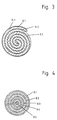
- Fig. 3 shows a support body which is formed by two sub-bodies, the two sub-bodies consisting of successive sections of a continuously continuous sheet metal strip, which loop around each other in a spiral.
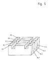
- FIG. 4 shows partial bodies which consist of sheet metal strips concentrically surrounding one another and FIG. 5 partial bodies which consist of sheet metal plates of constant thickness combined to form a package.
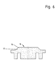
- FIG. 6 shows a molded part which is designed as a support body and consists of polymeric material in which electrically insulated particles of an electrically conductive powder are arranged. Since it is a one-piece design of the support body, this embodiment is not covered by the invention.
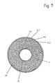
- Fig. 7 shows a support body, the partial body are formed by sheet metal strips which are non-conductively connected to each other and are fixed to an inner ring and an outer ring made of aluminum.
- the rubber bearing shown in Fig. 1 is intended for use in a motor vehicle. It essentially comprises a support body 4, which is screwed to the body of the motor vehicle during its intended use and which at the same time serves to support the hollow cone-shaped expansion spring 5 made of rubber-elastic material.
- the inflation spring 5 and the supporting body 4 on the one hand, and the housing 6 of the rubber bearing on the other hand, are connected in a non-detachable manner, for example by directly vulcanizing the expansion spring 5 onto the metal components adjacent on both sides.
- the housing 6 is closed on the underside and is connected to the internal combustion engine to be supported during the intended use.
- the two partial bodies 8.1, 8.2 can be subdivided further, these additional partial bodies also being separated from one another by electrically insulating layers.
- a circular leaf spring 2 is mounted in the area of the outer circumference of the sub-bodies 8.1 and 8.2, which engages behind the plate 3 made of soft iron in the area of its inner circumference and supports it in the direction of the magnet coil 9.
- the leaf spring 2 can prestress the plate 3 in the direction of the liquid-filled working space 1, a part 2a clamping the leaf spring 2 being connected to the plate 3 in a liquid-tight manner.
- the working space 1 is delimited by the plate 3, the housing 6, the inflation spring 5 and the supporting body 4.
- the working space 1 is connected via a damping opening 13 to the compensation space 11, which is delimited by a bellows 12.
- the damping opening 13 can be arranged in the wall of the housing 6, for example, as in the embodiment shown here, and can be designed like a channel. Its cross-section is expediently coordinated with the elasticity of the inflation spring 5 in such a way that when vibrations of a frequency to be damped are introduced, a resonance movement of the liquid volume contained results and, as a result, a particularly good damping effect.
- the at least two-part design of the support body 10 in sub-bodies 8.1, 8.2 causes an interruption of the eddy currents, as a result of which a rise in temperature, which would reduce the service life, is reliably prevented. It should generally be noted that the less eddy currents are formed, the finer the supporting body 10 is divided into sub-bodies 8.1, 8.2, ..., 8.n, which are separated from one another by electrically insulating layers 14.
- the electrically insulating layer 14 can consist both of a solid material and of an air-filled intermediate space, as shown for example in FIG. 2.
- the bearing shown in FIG. 2 essentially corresponds to that shown in FIG. 1, but between the two partial bodies 8.1, 8.2 there is an electrically insulating layer 14 which is formed by an air-filled intermediate space.
- Fig. 3 shows two sub-bodies 8.1, 8.2 which consist of successive sections of a continuously continuous sheet metal strip and loop around each other in a spiral.
- a thin-walled coating 14.1, 14.2 made of an electrically insulating material is provided as the insulating layer 14, which encloses the partial body 8.1 on both sides along its circumferential surfaces.
- This coating 14.1, 14.2 can be produced, for example, by immersing the partial body 8.1.
- the second partial body 8.2, which in this case has no electrically insulating coating, is arranged in the spiral passages of the first partial body 8.1.
- multi-part designs are also conceivable, but must also be separated from one another by an electrically insulating layer. The formation of eddy currents and the associated increase in temperature can be reduced with an increasing number of sheet metal strips which spiral around one another.
- FIG. 4 shows circular sheet metal strips 8.1-8.5 which have different diameters and surround one another concentrically.
- the sheet metal strips 8.1 to 8.5 are slotted at least once in the radial direction on the circumference.
- the electrically insulating layer consists of an air gap, but the metal strips can also be coated, as shown in FIG. 3. As the number of sheet metal strips increases, the risk of eddy current formation is reduced.
- the individual sub-bodies 8.1 to 8.5 in the form of sheet metal strips, are particularly easy to manufacture. This is particularly advantageous in economic terms.
- the individual metal strips are separated from one another by an insulating coating 14.1 to 14.4.
- the embodiment of this Support body is only an example.
- FIG. 6 shows a one-piece support body which consists of a molded part 18.
- This molded part 18 is formed by particles 16 of an electrically and magnetically conductive powder, the powder being glued in an electrically insulating manner by a binder 17 made of polymer material.
- the size of the particles 16 is in the range of a few micrometers.
- the molded part has a density which differs only slightly from that of an iron molded part, provided that these particles are iron particles.
- the assembly of such molded parts 18 in controllable rubber bearings is particularly simple.
- FIG. 7 shows a schematically represented support body, the sub-bodies 8.1, 8.2. Of which have an involute shape in the form of sheet metal plates of constant thickness and are fixed between an inner 19 and outer support ring 20.
- the area of the groove in which the magnet coil 9 is later arranged is shown with broken lines.
- the inner and the outer support ring 19, 20 consist of a non-magnetizable material.
- the insulating layers 14.1, 14.2, .... are made very thin, so that they cannot be shown in this drawing.
Landscapes
- Engineering & Computer Science (AREA)
- General Engineering & Computer Science (AREA)
- Mechanical Engineering (AREA)
- Vibration Prevention Devices (AREA)
- Magnetic Bearings And Hydrostatic Bearings (AREA)
- Fluid-Damping Devices (AREA)
- Combined Devices Of Dampers And Springs (AREA)
- Support Of The Bearing (AREA)
Claims (12)
- Support en caoutchouc réglable avec dispositif hydraulique d'amortissement, dans lequel il est prévu une chambre de travail (1) remplie de liquide, qui est délimitée au moins dans une zone partielle par une plaque (3) imperméable au liquide, formée d'un matériau magnétisable et qui est soutenue élastiquement et est déplaçable alternativement par un enroulement d'excitation (9) en direction de la chambre de travail (1), l'enroulement d'excitation (9) étant disposé sur le côté de la plaque (3) qui est opposé à la chambre de travail (1) et étant séparé de la plaque (3) par un intervalle d'air, l'enroulement d'excitation étant disposé dans une rainure d'un corps d'appui en fer doux, caractérisé en ce que le corps d'appui (10) comporte, au moins à l'intérieur de l'enroulement d'excitation (9) et dans son étendue axiale au moins deux corps partiels (8.1, 8.2) situés dans des positions mutuellement opposées et séparés l'un de l'autre par une couche électriquement isolante (14), qui s'étend parallèlement à la direction de mouvement de la plaque (3) et sensiblement perpendiculairement à la rainure et par conséquent dans la direction axiale de l'enroulement d'excitation (9).
- Support en caoutchouc selon la revendication 1, caractérisé en ce que la couche électriquement isolante (14) se compose d'un matériau solide.
- Support en caoutchouc selon la revendication 1, caractérisé en ce que la couche électriquement isolante (14) se compose d'un volume intermédiaire rempli d'air.
- Support en caoutchouc selon une des revendications 1 à 3, caractérisé en ce que les corps partiels (8.1, 8.2) se composent de parties successives d'une bande de tôle continue, qui s'entourent mutuellement en forme de spirale.
- Support en caoutchouc selon une des revendications 1 à 3, caractérisé en ce que les corps partiels (8.1, 8.2) se composent de bandes de tôle s'entourant mutuellement de façon concentrique et en ce que les bandes de tôle comportent dans une direction radiale au moins une perforation.
- Support en caoutchouc selon une des revendications 1 à 3, caractérisé en ce que les corps partiels (8.1, 8.2) se composent de plaques de tôle d'épaisseur constante et réunis sous forme d'un paquet.
- Support en caoutchouc selon la revendication 6, caractérisé en ce que les plaques de tôle entourent en forme de développante le centre de l'enroulement d'excitation (9).
- Support en caoutchouc selon une des revendications 1 à 3, caractérisé en ce que les corps partiels (8.1, 8.2) sont constitués par des colonnes (15) s'étendant parallèlement entre elles.
- Support en caoutchouc selon la revendication 8, caractérise en ce que les colonnes (15) sont reliées entre elles, à l'extérieur de l'étendue axiale de l'enroulement d'excitation (9), aux extrémités dirigées vers la plaque (3).
- Support en caoutchouc selon la revendication 9, caractérisé en ce que les colonnes (15) sont constituées par des saillies du corps d'appui (10) et sont agencées, du côté de l'enroulement d'excitation (9) qui est opposé à la plaque (3), de façon à se rejoindre mutuellement d'une seule pièce.
- Support en caoutchouc selon une des revendications 1 et 2, caractérisé en ce que les corps partiels (8.1, 8.2) sont constitués par des particules (16) d'une poudre et en ce que les particules (16) sont collées de façon électriquement isolante au moyen d'un liant (17) formé d'un matériau polymère.
- Support en caoutchouc selon la revendication 11, caractérisé en ce que les corps partiels (8.1, 8.2) sont collés sous forme d'une pièce profilée (18) constituant le corps d'appui (10).
Applications Claiming Priority (2)
| Application Number | Priority Date | Filing Date | Title |
|---|---|---|---|
| DE4127502 | 1991-08-20 | ||
| DE4127502 | 1991-08-20 |
Publications (2)
| Publication Number | Publication Date |
|---|---|
| EP0528111A1 EP0528111A1 (fr) | 1993-02-24 |
| EP0528111B1 true EP0528111B1 (fr) | 1994-09-14 |
Family
ID=6438672
Family Applications (1)
| Application Number | Title | Priority Date | Filing Date |
|---|---|---|---|
| EP92107864A Expired - Lifetime EP0528111B1 (fr) | 1991-08-20 | 1992-05-11 | Support en caoutchouc à régler |
Country Status (6)
| Country | Link |
|---|---|
| US (1) | US5273263A (fr) |
| EP (1) | EP0528111B1 (fr) |
| JP (1) | JPH05196087A (fr) |
| BR (1) | BR9203218A (fr) |
| DE (1) | DE59200498D1 (fr) |
| ES (1) | ES2059177T3 (fr) |
Families Citing this family (8)
| Publication number | Priority date | Publication date | Assignee | Title |
|---|---|---|---|---|
| JP2538468B2 (ja) * | 1991-12-06 | 1996-09-25 | 東海ゴム工業株式会社 | 流体封入式防振装置 |
| US5824728A (en) | 1995-06-09 | 1998-10-20 | Scot H. Laney | Iron-ferrite-filled polymer-based composite material and method of making the same |
| JP3409682B2 (ja) * | 1998-03-06 | 2003-05-26 | 日産自動車株式会社 | 防振支持装置 |
| US7007934B2 (en) * | 2001-07-02 | 2006-03-07 | Tokai Rubber Industries, Ltd. | Fluid-filled vibration damping device |
| US6565073B1 (en) | 2002-04-17 | 2003-05-20 | Meritor Light Vehicle Technology, Llc | Electromagnetic suspension system |
| WO2010032966A2 (fr) * | 2008-09-17 | 2010-03-25 | 전남대학교산학협력단 | Réducteur de vibrations par courants de foucault comprenant un matériau composite polymère ionique-métal et réducteur faisant intervenir des courants de foucault |
| CN104454991B (zh) * | 2014-12-23 | 2017-03-01 | 江苏理工学院 | 自感应磁轴承 |
| CN115182957B (zh) * | 2022-06-24 | 2023-06-02 | 安徽工程大学 | 一种用于灌浆软管振动抑制的主动电磁柔顺装置及方法 |
Family Cites Families (16)
| Publication number | Priority date | Publication date | Assignee | Title |
|---|---|---|---|---|
| JPS608540A (ja) * | 1983-06-27 | 1985-01-17 | Nissan Motor Co Ltd | 防振装置 |
| JPS60234144A (ja) * | 1984-05-03 | 1985-11-20 | Toyoda Gosei Co Ltd | 液体封入防振装置 |
| DE3419437A1 (de) * | 1984-05-24 | 1985-11-28 | Metzeler Kautschuk GmbH, 8000 München | Zweikammer-motorlager mit hydraulischer daempfung |
| DE3525673A1 (de) * | 1985-07-18 | 1987-01-22 | Metzeler Kautschuk | Aktives zweikammer-motorlager mit hydraulischer daempfung |
| JPS62288741A (ja) * | 1986-06-06 | 1987-12-15 | Tokai Rubber Ind Ltd | パワ−ユニツトのマウンテイング装置 |
| DE3619685A1 (de) * | 1986-06-11 | 1987-12-17 | Freudenberg Carl Fa | Zweikammermotorlager |
| DE3619687A1 (de) * | 1986-06-11 | 1987-12-17 | Freudenberg Carl Fa | Zweikammermotorlager |
| JPS631833A (ja) * | 1986-06-20 | 1988-01-06 | Tokai Rubber Ind Ltd | 流体封入式防振支持装置 |
| US4861006A (en) * | 1986-09-16 | 1989-08-29 | Bridgestone Corporation | Anti-vibration apparatus |
| JPS6412044A (en) * | 1987-07-01 | 1989-01-17 | Honda Motor Co Ltd | Intake device of internal combustion engine |
| DE3721866A1 (de) * | 1987-07-02 | 1989-01-12 | Boge Ag | Hydraulisch daempfendes gummilager |
| JPH083343B2 (ja) * | 1987-08-11 | 1996-01-17 | 日産自動車株式会社 | 制御型パワ−ユニットマウント装置 |
| US5000299A (en) * | 1989-02-07 | 1991-03-19 | Tokai Rubber Industries, Ltd. | Shock absorber using electro-viscous fluid |
| DE3918753C1 (fr) * | 1989-06-08 | 1990-07-12 | Fa. Carl Freudenberg, 6940 Weinheim, De | |
| FR2657666B1 (fr) * | 1990-01-30 | 1992-05-15 | Hutchinson Sa | Perfectionnements aux dispositifs antivibratoires hydrauliques. |
| JPH04131538A (ja) * | 1990-09-19 | 1992-05-06 | Tokai Rubber Ind Ltd | 高粘性流体封入式マウント装置 |
-
1992
- 1992-05-11 EP EP92107864A patent/EP0528111B1/fr not_active Expired - Lifetime
- 1992-05-11 DE DE59200498T patent/DE59200498D1/de not_active Expired - Fee Related
- 1992-05-11 ES ES92107864T patent/ES2059177T3/es not_active Expired - Lifetime
- 1992-07-31 US US07/923,290 patent/US5273263A/en not_active Expired - Fee Related
- 1992-08-19 JP JP4220274A patent/JPH05196087A/ja active Pending
- 1992-08-19 BR BR929203218A patent/BR9203218A/pt not_active IP Right Cessation
Also Published As
| Publication number | Publication date |
|---|---|
| US5273263A (en) | 1993-12-28 |
| DE59200498D1 (de) | 1994-10-20 |
| BR9203218A (pt) | 1993-04-06 |
| EP0528111A1 (fr) | 1993-02-24 |
| ES2059177T3 (es) | 1994-11-01 |
| JPH05196087A (ja) | 1993-08-06 |
Similar Documents
| Publication | Publication Date | Title |
|---|---|---|
| DE69011148T2 (de) | Stossdämpfer mit einer elektrorheologischen Flüssigkeit. | |
| DE3927715C2 (de) | Elastische Aufhängung mit einer Fluidfüllung | |
| DE69231617T2 (de) | Mit einem leitenden Material gefüllte Dichtung zur Abschirmung elektromagnetischer Wellen | |
| DE69329851T2 (de) | Magnetorheologische flüssigkeitsvorrichtungen | |
| DE69300371T2 (de) | Verbesserungen an hydraulischen schwingungsdämpfenden Vorrichtungen. | |
| DE60210731T2 (de) | Schwingungsdämpfungsvorrichtung | |
| EP0401463B1 (fr) | Support en caoutchouc à amortissement hydraulique | |
| DE3542917A1 (de) | Montageeinheit fuer einen antrieb | |
| DE4140854C2 (de) | Zylindrische, elastische Lagerung mit einer Fluidfüllung | |
| DE112015004653B4 (de) | Elektromagnetischer Schwingungsdämpfungsbetätiger, fluidgefüllte aktive Schwingungsdämpfungsvorrichtung und diese verwendende aktive Schwingungsregelvorrichtung | |
| EP2625769B1 (fr) | Rondelle de serrage pour fixer un stator dans le carter d'une machine électrique | |
| DE68925650T2 (de) | Flüssigkeitsgefüllte Buchsenfeder mit einem beweglichen Glied in der Flüssigkeitskammer | |
| DE10045701C2 (de) | Fluidgefüllter aktiver elastischer Träger, bei dem ein Schwingelement durch zwei elastische Stützelemente elastisch gestützt ist | |
| EP0528111B1 (fr) | Support en caoutchouc à régler | |
| EP1995088A2 (fr) | Elément de palier d'insertion, élément de palier d'insertion élastique et dispositif de support de jambe de suspension à ressort | |
| DE69010732T2 (de) | Oberes Lager für einen Stossdämpfer in einem Aufhängungssystem. | |
| EP0527302B1 (fr) | Support en caoutchouc à amortissement hydraulique | |
| DE69013063T2 (de) | Flüssigkeitsgefülltes, elastisches, zylindrisches Lager mit axial ausgedehnten und diametral gegenüberliegenden dünnwandigen elastischen Abschnitten. | |
| DE69808852T2 (de) | Elektromagnetischer Betätiger und hydraulisches Antischwingungslager mit einem solchen Betätiger | |
| DE2947018A1 (de) | Elastisches lager, insbesondere zur lagerung einer brennkraftmaschine in einem kraftfahrzeug | |
| DE102023104481B4 (de) | Antivibrationsvorrichtung | |
| DE3034651C2 (de) | Loslagerung für Wellen | |
| EP0541902B1 (fr) | Support élastique | |
| DE3908718A1 (de) | Elastische triebwerkaufhaengung mit einer fluidfuellung | |
| DE112021000031B4 (de) | Schwingungsisoliervorrichtung |
Legal Events
| Date | Code | Title | Description |
|---|---|---|---|
| PUAI | Public reference made under article 153(3) epc to a published international application that has entered the european phase |
Free format text: ORIGINAL CODE: 0009012 |
|
| 17P | Request for examination filed |
Effective date: 19921127 |
|
| AK | Designated contracting states |
Kind code of ref document: A1 Designated state(s): DE ES FR GB IT NL SE |
|
| 17Q | First examination report despatched |
Effective date: 19940301 |
|
| RAP3 | Party data changed (applicant data changed or rights of an application transferred) |
Owner name: FIRMA CARL FREUDENBERG |
|
| GRAA | (expected) grant |
Free format text: ORIGINAL CODE: 0009210 |
|
| ITF | It: translation for a ep patent filed | ||
| AK | Designated contracting states |
Kind code of ref document: B1 Designated state(s): DE ES FR GB IT NL SE |
|
| REF | Corresponds to: |
Ref document number: 59200498 Country of ref document: DE Date of ref document: 19941020 |
|
| REG | Reference to a national code |
Ref country code: ES Ref legal event code: FG2A Ref document number: 2059177 Country of ref document: ES Kind code of ref document: T3 |
|
| GBT | Gb: translation of ep patent filed (gb section 77(6)(a)/1977) |
Effective date: 19941019 |
|
| ET | Fr: translation filed | ||
| EAL | Se: european patent in force in sweden |
Ref document number: 92107864.8 |
|
| PGFP | Annual fee paid to national office [announced via postgrant information from national office to epo] |
Ref country code: SE Payment date: 19950420 Year of fee payment: 4 |
|
| PGFP | Annual fee paid to national office [announced via postgrant information from national office to epo] |
Ref country code: NL Payment date: 19950531 Year of fee payment: 4 |
|
| PLBE | No opposition filed within time limit |
Free format text: ORIGINAL CODE: 0009261 |
|
| STAA | Information on the status of an ep patent application or granted ep patent |
Free format text: STATUS: NO OPPOSITION FILED WITHIN TIME LIMIT |
|
| 26N | No opposition filed | ||
| PG25 | Lapsed in a contracting state [announced via postgrant information from national office to epo] |
Ref country code: SE Effective date: 19960512 |
|
| PG25 | Lapsed in a contracting state [announced via postgrant information from national office to epo] |
Ref country code: NL Effective date: 19961201 |
|
| EUG | Se: european patent has lapsed |
Ref document number: 92107864.8 |
|
| NLV4 | Nl: lapsed or anulled due to non-payment of the annual fee |
Effective date: 19961201 |
|
| REG | Reference to a national code |
Ref country code: GB Ref legal event code: IF02 |
|
| PGFP | Annual fee paid to national office [announced via postgrant information from national office to epo] |
Ref country code: ES Payment date: 20050509 Year of fee payment: 14 |
|
| PG25 | Lapsed in a contracting state [announced via postgrant information from national office to epo] |
Ref country code: ES Free format text: LAPSE BECAUSE OF NON-PAYMENT OF DUE FEES Effective date: 20060512 |
|
| PGFP | Annual fee paid to national office [announced via postgrant information from national office to epo] |
Ref country code: IT Payment date: 20060531 Year of fee payment: 15 |
|
| REG | Reference to a national code |
Ref country code: ES Ref legal event code: FD2A Effective date: 20060512 |
|
| PGFP | Annual fee paid to national office [announced via postgrant information from national office to epo] |
Ref country code: DE Payment date: 20090526 Year of fee payment: 18 Ref country code: FR Payment date: 20090519 Year of fee payment: 18 |
|
| PG25 | Lapsed in a contracting state [announced via postgrant information from national office to epo] |
Ref country code: IT Free format text: LAPSE BECAUSE OF NON-PAYMENT OF DUE FEES Effective date: 20070511 |
|
| PGFP | Annual fee paid to national office [announced via postgrant information from national office to epo] |
Ref country code: GB Payment date: 20100324 Year of fee payment: 19 |
|
| REG | Reference to a national code |
Ref country code: FR Ref legal event code: ST Effective date: 20110131 |
|
| PG25 | Lapsed in a contracting state [announced via postgrant information from national office to epo] |
Ref country code: DE Free format text: LAPSE BECAUSE OF NON-PAYMENT OF DUE FEES Effective date: 20101201 |
|
| PG25 | Lapsed in a contracting state [announced via postgrant information from national office to epo] |
Ref country code: FR Free format text: LAPSE BECAUSE OF NON-PAYMENT OF DUE FEES Effective date: 20100531 |
|
| GBPC | Gb: european patent ceased through non-payment of renewal fee |
Effective date: 20110511 |
|
| PG25 | Lapsed in a contracting state [announced via postgrant information from national office to epo] |
Ref country code: GB Free format text: LAPSE BECAUSE OF NON-PAYMENT OF DUE FEES Effective date: 20110511 |