EP0528162A2 - Chassis auxiliaire pour suspension de véhicule à moteur - Google Patents
Chassis auxiliaire pour suspension de véhicule à moteur Download PDFInfo
- Publication number
- EP0528162A2 EP0528162A2 EP92111666A EP92111666A EP0528162A2 EP 0528162 A2 EP0528162 A2 EP 0528162A2 EP 92111666 A EP92111666 A EP 92111666A EP 92111666 A EP92111666 A EP 92111666A EP 0528162 A2 EP0528162 A2 EP 0528162A2
- Authority
- EP
- European Patent Office
- Prior art keywords
- cross member
- auxiliary frame
- frame according
- bolt
- bearing
- Prior art date
- Legal status (The legal status is an assumption and is not a legal conclusion. Google has not performed a legal analysis and makes no representation as to the accuracy of the status listed.)
- Granted
Links
Images

Classifications
-
- B—PERFORMING OPERATIONS; TRANSPORTING
- B60—VEHICLES IN GENERAL
- B60G—VEHICLE SUSPENSION ARRANGEMENTS
- B60G3/00—Resilient suspensions for a single wheel
- B60G3/18—Resilient suspensions for a single wheel with two or more pivoted arms, e.g. parallelogram
- B60G3/20—Resilient suspensions for a single wheel with two or more pivoted arms, e.g. parallelogram all arms being rigid
-
- B—PERFORMING OPERATIONS; TRANSPORTING
- B60—VEHICLES IN GENERAL
- B60G—VEHICLE SUSPENSION ARRANGEMENTS
- B60G7/00—Pivoted suspension arms; Accessories thereof
- B60G7/02—Attaching arms to sprung part of vehicle
-
- B—PERFORMING OPERATIONS; TRANSPORTING
- B60—VEHICLES IN GENERAL
- B60G—VEHICLE SUSPENSION ARRANGEMENTS
- B60G2200/00—Indexing codes relating to suspension types
- B60G2200/10—Independent suspensions
- B60G2200/14—Independent suspensions with lateral arms
- B60G2200/144—Independent suspensions with lateral arms with two lateral arms forming a parallelogram
-
- B—PERFORMING OPERATIONS; TRANSPORTING
- B60—VEHICLES IN GENERAL
- B60G—VEHICLE SUSPENSION ARRANGEMENTS
- B60G2200/00—Indexing codes relating to suspension types
- B60G2200/10—Independent suspensions
- B60G2200/18—Multilink suspensions, e.g. elastokinematic arrangements
-
- B—PERFORMING OPERATIONS; TRANSPORTING
- B60—VEHICLES IN GENERAL
- B60G—VEHICLE SUSPENSION ARRANGEMENTS
- B60G2200/00—Indexing codes relating to suspension types
- B60G2200/40—Indexing codes relating to the wheels in the suspensions
- B60G2200/462—Toe-in/out
- B60G2200/4622—Alignment adjustment
-
- B—PERFORMING OPERATIONS; TRANSPORTING
- B60—VEHICLES IN GENERAL
- B60G—VEHICLE SUSPENSION ARRANGEMENTS
- B60G2200/00—Indexing codes relating to suspension types
- B60G2200/40—Indexing codes relating to the wheels in the suspensions
- B60G2200/464—Caster angle
-
- B—PERFORMING OPERATIONS; TRANSPORTING
- B60—VEHICLES IN GENERAL
- B60G—VEHICLE SUSPENSION ARRANGEMENTS
- B60G2204/00—Indexing codes related to suspensions per se or to auxiliary parts
- B60G2204/10—Mounting of suspension elements
- B60G2204/14—Mounting of suspension arms
-
- B—PERFORMING OPERATIONS; TRANSPORTING
- B60—VEHICLES IN GENERAL
- B60G—VEHICLE SUSPENSION ARRANGEMENTS
- B60G2204/00—Indexing codes related to suspensions per se or to auxiliary parts
- B60G2204/10—Mounting of suspension elements
- B60G2204/14—Mounting of suspension arms
- B60G2204/143—Mounting of suspension arms on the vehicle body or chassis
-
- B—PERFORMING OPERATIONS; TRANSPORTING
- B60—VEHICLES IN GENERAL
- B60G—VEHICLE SUSPENSION ARRANGEMENTS
- B60G2204/00—Indexing codes related to suspensions per se or to auxiliary parts
- B60G2204/10—Mounting of suspension elements
- B60G2204/15—Mounting of subframes
-
- B—PERFORMING OPERATIONS; TRANSPORTING
- B60—VEHICLES IN GENERAL
- B60G—VEHICLE SUSPENSION ARRANGEMENTS
- B60G2204/00—Indexing codes related to suspensions per se or to auxiliary parts
- B60G2204/40—Auxiliary suspension parts; Adjustment of suspensions
- B60G2204/42—Joints with cam surfaces
-
- B—PERFORMING OPERATIONS; TRANSPORTING
- B60—VEHICLES IN GENERAL
- B60G—VEHICLE SUSPENSION ARRANGEMENTS
- B60G2204/00—Indexing codes related to suspensions per se or to auxiliary parts
- B60G2204/61—Adjustable during maintenance
-
- B—PERFORMING OPERATIONS; TRANSPORTING
- B60—VEHICLES IN GENERAL
- B60G—VEHICLE SUSPENSION ARRANGEMENTS
- B60G2206/00—Indexing codes related to the manufacturing of suspensions: constructional features, the materials used, procedures or tools
- B60G2206/01—Constructional features of suspension elements, e.g. arms, dampers, springs
- B60G2206/60—Subframe construction
Definitions
- the invention relates to a subframe for a wheel suspension of a motor vehicle according to the preamble of claim 1.
- a support frame for a wheel suspension of a vehicle which is attached to the vehicle body and includes bearing mounts for wheel control handlebars.
- This support frame consists of a carrier aligned transversely in the vehicle, which receives two link bearings for a semi-trailing arm axle at each end.
- a further embodiment of a subframe for a wheel suspension (DE-A 25 36 060) consists of a one-piece U-shaped carrier which is fastened to the vehicle body, the connection of the handlebar bearing to the vehicle body being carried out using the same fastening screw of the subframe.
- the object of the invention is to provide a lightweight subframe for a wheel suspension, which is designed in a simple design with reduced design effort.
- the main advantages achieved by the invention are that the complexity of the connections to the link bearings and the two-part subframe is reduced, since additional connections of the two parts of the subframe are omitted.
- an attachment of a first cross member to a second cross member of the frame is advantageously used to receive a link bearing for a wheel control arm, which means that additional heavy-duty bearing receptacles on the subframe can be omitted.
- a gap between the two cross members to be connected is used to receive the one link bearing in order to support the bearing on its two end faces via parallel wings.
- the gap is preferably formed between an arm extending from the leg of one cross member and a shoulder of a further cross member, the arm being connected at a distance from the bearing to the further cross member via a fastening screw.
- a further link bearing of a wheel control link is connected, which is arranged on the outside of a cross member, whereby the effort of an additional fastening screw in addition to a retaining screw for the bearing is advantageously avoided.
- a stabilizer bracket is connected via two fastening screws, one fastening screw receiving a third link bearing, which is arranged between the cross member and one leg of the bracket.
- This bolt holding the handlebar bearing comprises an eccentric adjusting element with which the caster of the wheel is adjusted.
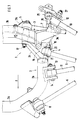
- the subframe 1 for a wheel suspension in particular for a rear suspension in a multi-link construction, comprises a first front cross member 2, which is connected to a second rear cross member 3 - with respect to the direction of travel F - to form a strength unit and is fastened to the vehicle body via several bearings.
- Bearings 4 and 8 for a lower wishbone 6 and a bearing 5 for a tie rod 7 are held on the auxiliary frame 1.
- the upper connection of the wheel suspension is formed by two links 10 and 11 with the bearings 12 and 13, the bearing 12 being provided on the subframe 1 and the bearing 13 on the vehicle body 14.
- the front cross member 2 is U-shaped with legs 2b extending from a transverse support part 2a and extends approximately in a horizontal plane X-X.
- the rear cross member 3 has end pillars 3a which extend vertically upward from a transverse support member 3b, which is approximately in the same plane X-X with the front cross member 2, with respect to the plane X-X.
- the two cross members 2 and 3 of the subframe 1 are connected to each other via fastening bolts 16, 17, which also serve to fasten the bearings 4 and 5 for the handlebars 6 and 7 at the same time.
- the bearing 4 of the handlebar 6 is fitted in a gap 18 formed between the arms 2c of the front cross member 2 and the rear cross member 3 and is held by the bolt 16 which simultaneously connects the two cross members 2 and 3.
- the gap 18 for receiving the bearing 4 is delimited by parallel surfaces 21, 22, which end faces of the bearing 4 face accordingly.
- the pivot axis formed by the bolt 16 extends at an obtuse angle to the leg 2b of the first cross member 2.
- the cross member 2 is connected via the arm 2c bent by the leg 2b to the transverse support part 3b of the cross member 3 via the further bolt 17.
- this supports the bearing 5 for the handlebar 7, which is arranged on the outside of the support part 3b.
- the bolt 17 can be held via a striking plate 17a connected to the supporting part 3b.
- cross beams 2 and 3 are connected to each other via the two bolts 16 and 17 on each side of the subframe 1 and at the same time the bearings 4, 5 are fixed on the subframe 1.
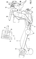
- a stabilizer bracket 25 is connected to the column 3a of the cross member 3 by means of fastening bolts 26, 27.
- the bolt 27 also carries the bearing 12 for the upper link 10, so that a separate attachment of the bearing 12 or the bearing block 25 is not necessary.
- the fastening bolt 27 is provided with an eccentric adjusting element 28.
- This comprises an eccentric disk 29 with a hexagon 30, which is connected in a rotationally fixed manner to the screw 27, the end-side head of which is formed by a second eccentric disk 29a, which is arranged in a groove with lateral ramps.
- the hexagon 30 can be offset by the eccentricity e1 from the pin axis 34 in order to make the eccentric disk 29 smaller and thus lighter.
- the bolt connection is secured by means of a fastening nut 31.
- the eccentric disc 29 is rotated via the hexagon 30 between limits 32 and 33 of the bearing block 25, so that the bolt axis 34 is displaced and thus the wheel is displaced.
- This arrangement has the advantage that the screw connection is set and secured from an outer side, in particular if access to the end head of the screw 27 is not possible.
Landscapes
- Engineering & Computer Science (AREA)
- Mechanical Engineering (AREA)
- Body Structure For Vehicles (AREA)
- Vehicle Body Suspensions (AREA)
Applications Claiming Priority (2)
| Application Number | Priority Date | Filing Date | Title |
|---|---|---|---|
| DE4127037A DE4127037C2 (de) | 1991-08-16 | 1991-08-16 | Hilfsrahmen für eine Radaufhängung eines Kraftfahrzeugs |
| DE4127037 | 1991-08-16 |
Publications (3)
| Publication Number | Publication Date |
|---|---|
| EP0528162A2 true EP0528162A2 (fr) | 1993-02-24 |
| EP0528162A3 EP0528162A3 (en) | 1993-06-09 |
| EP0528162B1 EP0528162B1 (fr) | 1994-12-14 |
Family
ID=6438390
Family Applications (1)
| Application Number | Title | Priority Date | Filing Date |
|---|---|---|---|
| EP92111666A Expired - Lifetime EP0528162B1 (fr) | 1991-08-16 | 1992-07-09 | Chassis auxiliaire pour suspension de véhicule à moteur |
Country Status (4)
| Country | Link |
|---|---|
| US (1) | US5240279A (fr) |
| EP (1) | EP0528162B1 (fr) |
| JP (1) | JPH05193519A (fr) |
| DE (2) | DE4127037C2 (fr) |
Families Citing this family (11)
| Publication number | Priority date | Publication date | Assignee | Title |
|---|---|---|---|---|
| DE19529334C2 (de) * | 1994-08-18 | 1997-06-26 | Honda Motor Co Ltd | Unterrahmen für ein Kraftfahrzeug |
| AU8071498A (en) | 1997-10-31 | 1999-05-24 | Constant Velocity | Independent rear suspension system |
| DE19909945C1 (de) * | 1999-03-06 | 2000-10-26 | Porsche Ag | Fahrschemel für ein Kraftfahrzeug |
| DE10011420B4 (de) * | 2000-03-09 | 2005-10-06 | Daimlerchrysler Ag | Doppelpendelachse mit geteiltem Montagehilfsrahmen |
| DE10153272B4 (de) * | 2000-11-01 | 2009-04-16 | Honda Giken Kogyo K.K. | Druckguss-Hilfsrahmen |
| DE10312166A1 (de) * | 2003-03-19 | 2004-09-30 | Volkswagen Ag | Achsanordnung für ein Kraftfahrzeug |
| US7429054B1 (en) * | 2005-12-14 | 2008-09-30 | Heckethorn Products, Inc. | Non-drop torsion bar bracket and assembly |
| DE102006001709A1 (de) * | 2006-01-13 | 2007-07-26 | Audi Ag | Hilfsrahmen für ein Kraftfahrzeug, insbesondere für einen Personenkraftwagen |
| US7648170B2 (en) * | 2006-08-16 | 2010-01-19 | Honda Motor Co., Ltd. | Interchangeable suspension system |
| DE102016000670B3 (de) | 2016-01-22 | 2017-01-12 | Audi Ag | Hilfsrahmen für ein zweispuriges Kraftfahrzeug |
| DE102018219905B4 (de) | 2018-11-21 | 2025-03-20 | Audi Ag | Hilfsrahmen für ein Kraftfahrzeug sowie Kraftfahrzeug mit einem solchen Hilfsrahmen |
Family Cites Families (11)
| Publication number | Priority date | Publication date | Assignee | Title |
|---|---|---|---|---|
| US3584895A (en) * | 1969-10-07 | 1971-06-15 | Nissan Motor | Automotive suspension mechanism |
| CS170392B1 (fr) * | 1973-08-30 | 1976-08-27 | ||
| DE2536060C2 (de) * | 1975-08-13 | 1987-05-27 | Volkswagenwerk Ag, 3180 Wolfsburg | Radaufhängung für Kraftfahrzeuge |
| IT1128058B (it) * | 1980-03-20 | 1986-05-28 | Fiat Auto Spa | Autoveicolo provvisto di mezzi per la sospensione indipendente delle ruote anteriori |
| JPS62105709A (ja) * | 1985-11-05 | 1987-05-16 | Toyota Motor Corp | 車両のサスペンシヨン |
| FR2614000B1 (fr) * | 1987-04-14 | 1991-04-05 | Renault | Element de chassis pour suspension de vehicules automobiles a roues independantes a bras inferieurs transversaux |
| JPS63263113A (ja) * | 1987-04-20 | 1988-10-31 | Daihatsu Motor Co Ltd | 後輪懸架装置のト−角制御装置 |
| IT1210804B (it) * | 1987-06-16 | 1989-09-29 | Ferrari Eng | Telaio anteriore facente parte di una struttura portante di una autovettura |
| JP2518863B2 (ja) * | 1987-09-03 | 1996-07-31 | 日産自動車株式会社 | ホイ―ルアライメント調整機構 |
| JPH0234413A (ja) * | 1988-07-25 | 1990-02-05 | Mazda Motor Corp | 車両の後輪懸架装置 |
| US5026090A (en) * | 1988-11-16 | 1991-06-25 | Honda Giken Kogyo Kabushiki Kaisha | Wheel suspension system for automobiles |
-
1991
- 1991-08-16 DE DE4127037A patent/DE4127037C2/de not_active Expired - Fee Related
-
1992
- 1992-07-09 DE DE59200962T patent/DE59200962D1/de not_active Expired - Fee Related
- 1992-07-09 EP EP92111666A patent/EP0528162B1/fr not_active Expired - Lifetime
- 1992-08-11 JP JP4214051A patent/JPH05193519A/ja active Pending
- 1992-08-17 US US07/930,625 patent/US5240279A/en not_active Expired - Fee Related
Also Published As
| Publication number | Publication date |
|---|---|
| US5240279A (en) | 1993-08-31 |
| EP0528162A3 (en) | 1993-06-09 |
| EP0528162B1 (fr) | 1994-12-14 |
| DE4127037A1 (de) | 1993-02-18 |
| DE4127037C2 (de) | 1995-04-27 |
| JPH05193519A (ja) | 1993-08-03 |
| DE59200962D1 (de) | 1995-01-26 |
Similar Documents
| Publication | Publication Date | Title |
|---|---|---|
| EP0603536B1 (fr) | Véhicule à moteur avec éléments de renfort de la carrosserie | |
| EP1193087B1 (fr) | Suspension de roue pour véhicules automobiles | |
| EP0324913B1 (fr) | Essieu avant | |
| EP0530594A1 (fr) | Cadre auxiliaire pour un véhicule automobile | |
| DE3514788A1 (de) | Radaufhaengung | |
| DE102007063544A1 (de) | Radaufhängung für eine Vorderachse eines Kraftfahrzeugs | |
| DE4244216C2 (de) | Kraftfahrzeugkarosserie | |
| EP0528162B1 (fr) | Chassis auxiliaire pour suspension de véhicule à moteur | |
| DE19624242A1 (de) | Vorrichtung zur Querführung einer Starrachse eines Kraftfahrzeuges | |
| EP0940320A1 (fr) | Chassis pour véhicule utilitaire lourd | |
| EP0940319B1 (fr) | Chassis d'un véhicule utilitaire lourd | |
| DE10018315A1 (de) | Achsaufhängung für eine luftgefederte Fahrzeugachse | |
| DE3151369C2 (de) | Radaufhängung | |
| DE29705672U1 (de) | Fahrzeuganhänger mit höhenverstellbarer Achsbockbefestigung | |
| EP2780182A1 (fr) | Essieu rigide à suspension pneumatique | |
| EP1475254B1 (fr) | Fixation d'essieu pour un essieu de véhicule | |
| DE4237533C1 (de) | Querträger für einen Fahrschemel | |
| DE102018110576B3 (de) | Einzelradaufhängung für einen Fahrzeuganhänger und Herstellungsverfahren | |
| EP0764571B1 (fr) | Traverse d'essieu avant d'un véhicule automobile | |
| DE19824637A1 (de) | Fahrzeug-Rahmen-Aufbau | |
| EP1598260B1 (fr) | Connection d'un bras de suspension du côté carosserie d'un véhicule automobile | |
| DE102022104294A1 (de) | Federsitzhalterung für fahrzeugaufhängung | |
| DE19809196A1 (de) | Fahrgestell eines schweren Nutzfahrzeuges | |
| EP0940321B1 (fr) | Chassis pour véhicule utilitaire lourd | |
| EP0754576A1 (fr) | Suspension d'un essieu directeur d'un véhicule tout-terrain |
Legal Events
| Date | Code | Title | Description |
|---|---|---|---|
| PUAI | Public reference made under article 153(3) epc to a published international application that has entered the european phase |
Free format text: ORIGINAL CODE: 0009012 |
|
| AK | Designated contracting states |
Kind code of ref document: A2 Designated state(s): DE FR GB IT |
|
| PUAL | Search report despatched |
Free format text: ORIGINAL CODE: 0009013 |
|
| AK | Designated contracting states |
Kind code of ref document: A3 Designated state(s): DE FR GB IT |
|
| 17P | Request for examination filed |
Effective date: 19931111 |
|
| 17Q | First examination report despatched |
Effective date: 19931202 |
|
| ITF | It: translation for a ep patent filed | ||
| GRAA | (expected) grant |
Free format text: ORIGINAL CODE: 0009210 |
|
| AK | Designated contracting states |
Kind code of ref document: B1 Designated state(s): DE FR GB IT |
|
| REF | Corresponds to: |
Ref document number: 59200962 Country of ref document: DE Date of ref document: 19950126 |
|
| GBT | Gb: translation of ep patent filed (gb section 77(6)(a)/1977) |
Effective date: 19950104 |
|
| ET | Fr: translation filed | ||
| PLBE | No opposition filed within time limit |
Free format text: ORIGINAL CODE: 0009261 |
|
| STAA | Information on the status of an ep patent application or granted ep patent |
Free format text: STATUS: NO OPPOSITION FILED WITHIN TIME LIMIT |
|
| 26N | No opposition filed | ||
| PGFP | Annual fee paid to national office [announced via postgrant information from national office to epo] |
Ref country code: GB Payment date: 19960716 Year of fee payment: 5 |
|
| PGFP | Annual fee paid to national office [announced via postgrant information from national office to epo] |
Ref country code: FR Payment date: 19960729 Year of fee payment: 5 |
|
| PGFP | Annual fee paid to national office [announced via postgrant information from national office to epo] |
Ref country code: DE Payment date: 19960819 Year of fee payment: 5 |
|
| PG25 | Lapsed in a contracting state [announced via postgrant information from national office to epo] |
Ref country code: GB Free format text: LAPSE BECAUSE OF NON-PAYMENT OF DUE FEES Effective date: 19970709 |
|
| GBPC | Gb: european patent ceased through non-payment of renewal fee |
Effective date: 19970709 |
|
| PG25 | Lapsed in a contracting state [announced via postgrant information from national office to epo] |
Ref country code: FR Free format text: LAPSE BECAUSE OF NON-PAYMENT OF DUE FEES Effective date: 19980331 |
|
| PG25 | Lapsed in a contracting state [announced via postgrant information from national office to epo] |
Ref country code: DE Free format text: LAPSE BECAUSE OF NON-PAYMENT OF DUE FEES Effective date: 19980401 |
|
| REG | Reference to a national code |
Ref country code: FR Ref legal event code: ST |
|
| PG25 | Lapsed in a contracting state [announced via postgrant information from national office to epo] |
Ref country code: IT Free format text: LAPSE BECAUSE OF NON-PAYMENT OF DUE FEES;WARNING: LAPSES OF ITALIAN PATENTS WITH EFFECTIVE DATE BEFORE 2007 MAY HAVE OCCURRED AT ANY TIME BEFORE 2007. THE CORRECT EFFECTIVE DATE MAY BE DIFFERENT FROM THE ONE RECORDED. Effective date: 20050709 |