EP0940320A1 - Chassis pour véhicule utilitaire lourd - Google Patents
Chassis pour véhicule utilitaire lourd Download PDFInfo
- Publication number
- EP0940320A1 EP0940320A1 EP99101606A EP99101606A EP0940320A1 EP 0940320 A1 EP0940320 A1 EP 0940320A1 EP 99101606 A EP99101606 A EP 99101606A EP 99101606 A EP99101606 A EP 99101606A EP 0940320 A1 EP0940320 A1 EP 0940320A1
- Authority
- EP
- European Patent Office
- Prior art keywords
- strut
- rigid axle
- chassis according
- axle
- rigid
- Prior art date
- Legal status (The legal status is an assumption and is not a legal conclusion. Google has not performed a legal analysis and makes no representation as to the accuracy of the status listed.)
- Granted
Links
Images


Classifications
-
- B—PERFORMING OPERATIONS; TRANSPORTING
- B60—VEHICLES IN GENERAL
- B60G—VEHICLE SUSPENSION ARRANGEMENTS
- B60G9/00—Resilient suspensions of a rigid axle or axle housing for two or more wheels
- B60G9/003—Resilient suspensions of a rigid axle or axle housing for two or more wheels the axle being rigidly connected to a trailing guiding device
-
- B—PERFORMING OPERATIONS; TRANSPORTING
- B60—VEHICLES IN GENERAL
- B60G—VEHICLE SUSPENSION ARRANGEMENTS
- B60G15/00—Resilient suspensions characterised by arrangement, location or type of combined spring and vibration damper, e.g. telescopic type
- B60G15/08—Resilient suspensions characterised by arrangement, location or type of combined spring and vibration damper, e.g. telescopic type having fluid spring
- B60G15/12—Resilient suspensions characterised by arrangement, location or type of combined spring and vibration damper, e.g. telescopic type having fluid spring and fluid damper
-
- B—PERFORMING OPERATIONS; TRANSPORTING
- B62—LAND VEHICLES FOR TRAVELLING OTHERWISE THAN ON RAILS
- B62D—MOTOR VEHICLES; TRAILERS
- B62D21/00—Understructures, i.e. chassis frame on which a vehicle body may be mounted
- B62D21/11—Understructures, i.e. chassis frame on which a vehicle body may be mounted with resilient means for suspension, e.g. of wheels or engine; sub-frames for mounting engine or suspensions
-
- B—PERFORMING OPERATIONS; TRANSPORTING
- B62—LAND VEHICLES FOR TRAVELLING OTHERWISE THAN ON RAILS
- B62D—MOTOR VEHICLES; TRAILERS
- B62D25/00—Superstructure or monocoque structure sub-units; Parts or details thereof not otherwise provided for
- B62D25/08—Front or rear portions
- B62D25/088—Details of structures as upper supports for springs or dampers
-
- B—PERFORMING OPERATIONS; TRANSPORTING
- B62—LAND VEHICLES FOR TRAVELLING OTHERWISE THAN ON RAILS
- B62D—MOTOR VEHICLES; TRAILERS
- B62D33/00—Superstructures for load-carrying vehicles
- B62D33/06—Drivers' cabs
- B62D33/063—Drivers' cabs movable from one position into at least one other position, e.g. tiltable, pivotable about a vertical axis, displaceable from one side of the vehicle to the other
- B62D33/067—Drivers' cabs movable from one position into at least one other position, e.g. tiltable, pivotable about a vertical axis, displaceable from one side of the vehicle to the other tiltable
-
- B—PERFORMING OPERATIONS; TRANSPORTING
- B60—VEHICLES IN GENERAL
- B60G—VEHICLE SUSPENSION ARRANGEMENTS
- B60G2200/00—Indexing codes relating to suspension types
- B60G2200/30—Rigid axle suspensions
- B60G2200/31—Rigid axle suspensions with two trailing arms rigidly connected to the axle
-
- B—PERFORMING OPERATIONS; TRANSPORTING
- B60—VEHICLES IN GENERAL
- B60G—VEHICLE SUSPENSION ARRANGEMENTS
- B60G2200/00—Indexing codes relating to suspension types
- B60G2200/30—Rigid axle suspensions
- B60G2200/34—Stabilising mechanisms, e.g. for lateral stability
- B60G2200/341—Panhard rod
-
- B—PERFORMING OPERATIONS; TRANSPORTING
- B60—VEHICLES IN GENERAL
- B60G—VEHICLE SUSPENSION ARRANGEMENTS
- B60G2202/00—Indexing codes relating to the type of spring, damper or actuator
- B60G2202/30—Spring/Damper and/or actuator Units
- B60G2202/31—Spring/Damper and/or actuator Units with the spring arranged around the damper, e.g. MacPherson strut
- B60G2202/314—The spring being a pneumatic spring
-
- B—PERFORMING OPERATIONS; TRANSPORTING
- B60—VEHICLES IN GENERAL
- B60G—VEHICLE SUSPENSION ARRANGEMENTS
- B60G2204/00—Indexing codes related to suspensions per se or to auxiliary parts
- B60G2204/10—Mounting of suspension elements
- B60G2204/12—Mounting of springs or dampers
- B60G2204/126—Mounting of pneumatic springs
-
- B—PERFORMING OPERATIONS; TRANSPORTING
- B60—VEHICLES IN GENERAL
- B60G—VEHICLE SUSPENSION ARRANGEMENTS
- B60G2204/00—Indexing codes related to suspensions per se or to auxiliary parts
- B60G2204/10—Mounting of suspension elements
- B60G2204/12—Mounting of springs or dampers
- B60G2204/128—Damper mount on vehicle body or chassis
-
- B—PERFORMING OPERATIONS; TRANSPORTING
- B60—VEHICLES IN GENERAL
- B60G—VEHICLE SUSPENSION ARRANGEMENTS
- B60G2204/00—Indexing codes related to suspensions per se or to auxiliary parts
- B60G2204/10—Mounting of suspension elements
- B60G2204/12—Mounting of springs or dampers
- B60G2204/129—Damper mount on wheel suspension or knuckle
-
- B—PERFORMING OPERATIONS; TRANSPORTING
- B60—VEHICLES IN GENERAL
- B60G—VEHICLE SUSPENSION ARRANGEMENTS
- B60G2204/00—Indexing codes related to suspensions per se or to auxiliary parts
- B60G2204/10—Mounting of suspension elements
- B60G2204/14—Mounting of suspension arms
- B60G2204/143—Mounting of suspension arms on the vehicle body or chassis
-
- B—PERFORMING OPERATIONS; TRANSPORTING
- B60—VEHICLES IN GENERAL
- B60G—VEHICLE SUSPENSION ARRANGEMENTS
- B60G2204/00—Indexing codes related to suspensions per se or to auxiliary parts
- B60G2204/10—Mounting of suspension elements
- B60G2204/14—Mounting of suspension arms
- B60G2204/148—Mounting of suspension arms on the unsprung part of the vehicle, e.g. wheel knuckle or rigid axle
-
- B—PERFORMING OPERATIONS; TRANSPORTING
- B60—VEHICLES IN GENERAL
- B60G—VEHICLE SUSPENSION ARRANGEMENTS
- B60G2206/00—Indexing codes related to the manufacturing of suspensions: constructional features, the materials used, procedures or tools
- B60G2206/01—Constructional features of suspension elements, e.g. arms, dampers, springs
- B60G2206/30—Constructional features of rigid axles
- B60G2206/312—Cranked axle
-
- B—PERFORMING OPERATIONS; TRANSPORTING
- B60—VEHICLES IN GENERAL
- B60G—VEHICLE SUSPENSION ARRANGEMENTS
- B60G2206/00—Indexing codes related to the manufacturing of suspensions: constructional features, the materials used, procedures or tools
- B60G2206/01—Constructional features of suspension elements, e.g. arms, dampers, springs
- B60G2206/60—Subframe construction
- B60G2206/601—Hanger bracket
-
- B—PERFORMING OPERATIONS; TRANSPORTING
- B60—VEHICLES IN GENERAL
- B60G—VEHICLE SUSPENSION ARRANGEMENTS
- B60G2206/00—Indexing codes related to the manufacturing of suspensions: constructional features, the materials used, procedures or tools
- B60G2206/01—Constructional features of suspension elements, e.g. arms, dampers, springs
- B60G2206/60—Subframe construction
- B60G2206/602—Single transverse beam
-
- B—PERFORMING OPERATIONS; TRANSPORTING
- B60—VEHICLES IN GENERAL
- B60G—VEHICLE SUSPENSION ARRANGEMENTS
- B60G2206/00—Indexing codes related to the manufacturing of suspensions: constructional features, the materials used, procedures or tools
- B60G2206/01—Constructional features of suspension elements, e.g. arms, dampers, springs
- B60G2206/80—Manufacturing procedures
- B60G2206/82—Joining
- B60G2206/8207—Joining by screwing
-
- B—PERFORMING OPERATIONS; TRANSPORTING
- B60—VEHICLES IN GENERAL
- B60G—VEHICLE SUSPENSION ARRANGEMENTS
- B60G2300/00—Indexing codes relating to the type of vehicle
- B60G2300/02—Trucks; Load vehicles
- B60G2300/026—Heavy duty trucks
-
- B—PERFORMING OPERATIONS; TRANSPORTING
- B60—VEHICLES IN GENERAL
- B60G—VEHICLE SUSPENSION ARRANGEMENTS
- B60G2300/00—Indexing codes relating to the type of vehicle
- B60G2300/14—Buses
Definitions
- the invention relates to a chassis of a heavy commercial vehicle with features according to the preamble of claim 1.
- Suspension strut holder as a frame-fixed articulation, holding and support element for the Panhardstab saves you from having to use your own bearing block, which is otherwise necessary for this purpose in another place of the frame and also limits the inside of the U-shaped cross member does not unnecessarily give free space. It also helps save manufacturing and assembly costs. The same applies to the axle side Articulation point of the Panhard rod on the rigid axle-trailing arm assembly. Further Advantages of the solution according to the invention are specified in the description of the figures.
- the chassis according to the invention is part of a heavy commercial vehicle, which is a truck with a front-link design tilting cab and with attachments and superstructures of various types, too those for special purposes, a tractor unit or around a bus can act.
- the rigid axle according to the invention can be a front axle, Leading or trailing axle with steerable or non-steerable wheels act.
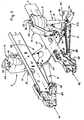
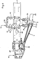
- Front axle shown. From the chassis are essential in the drawing Parts of the frame whose two longitudinal beams are labeled 1 and 2.
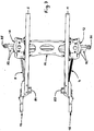
- the invention Rigid axle exists including all suspension, suspension and Damping elements from the following main parts, namely a rigid axle body 3, a left trailing arm 4 and right trailing arm 5, a left strut 6 with air or coil spring 7 and this coaxial shock absorber 8, a right Strut 9 with air or coil spring 10 and this coaxial shock absorber 11, a Panhard rod 15 and a U-shaped cross member 38, which are in detail from a left strut bracket 12, a right strut bracket 13 and a crossbar 14 is composed.
- a left multifunction bearing shield and 17 denotes a right multi-function bearing plate, each of which is outside is attached to a frame side member 1, 2 and for frame-side articulation the rigid axle according to the invention and beyond in the example shown also as a holding, support and bearing element for a larger number of vehicle parts to be attached serves.
- the rigid axle according to the invention is in the manner of a self-stabilizing torsion beam axle educated.
- the rigid axle is basically designed in this way is that only the Panhard rod 15 is necessary for their transverse guidance and they without the previously necessary in heavy commercial vehicles to limit swaying independent U-shaped stabilizer, but its function Component composite is stamped, which consists of the rigid axle body 3 and assembled on this attached trailing arms 4, 5.
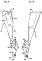
- This purpose and obeying function, the rigid axle body 3 is in a straight line Middle region 18 between the two trailing arms 4, 5 connected to it defined trained torsional.
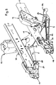
- End section 19 or 20 is on the end face - in the case of a drawn axis at the front and in the case of a pushed axle at the rear - on the rigid axle body 3 in each case a projection or protrusion with reworked contact surface 21 or 22, on each of the two trailing arms 4, 5 with its axle body side Foot 23 or 24 non-positively and if necessary also flanged positively is.
- the contact surface 21 or 22 extends with a large width preferably over the entire height available on the rigid axle body 3, around the rigid axle body 3 the largest possible connection base for the respective trailing arm 4 or 5 to provide.
- each trailing arm 4, 5 25, e.g. B. 4 pieces each, provided by the opposite side of the Rigid axle body 3 passed through through holes formed therein as well as in aligned blind hole tapped holes in the respective Trailing arm feet 23 and 24 are screwed in, with a high preload and secured so that the rigid axle-trailing arm connection with all Loads occurring during driving operation are perfectly preserved.
- the two, like the rigid axle 3 in the stabilizer function integrated trailing arm 4, 5 are each produced as a cast part, optionally also a forged part, subsequently machined or finished at certain points and in the vertical is comparatively rigid, but can be twisted to a limited extent about its longitudinal axis educated.
- each of the two trailing arms 4, 5 are rigid in terms of their bending strength and torsion ability in connection with the torsionable rigid axle body 3 on the overall stabilizing effect of the rigid axle-trailing arm assembly coordinated, and that about appropriate dimensioning and shaping of their cross sections.
- each of the two has the same length Trailing arm 4, 5 between his foot 23 and 24 and another existing one Bearing eye 26 and 27, a rod-shaped area with an over the Length changing cross-section.
- the two trailing arms 4, 5 to the vehicle longitudinal center axis mirror-symmetrical and - viewed from above - so swept towards each other standing connected to the rigid axle body 3 that they have a trapezoidal surface include, the distance between their bearing eyes 26 and 27 with which each on the multifunction bearing plates 16 and 17, which are fixed to the frame are articulated, is smaller than the distance between their axles-side feet 23 and 24. If the rigid axle according to the invention is installed in the vehicle, run the two trailing arms 4, 5 - viewed from the side - from the rigid axle body 3 proceeding diagonally upwards towards the frame-side multi-function shields 16 and 17 respectively.
- the rigid axle according to the invention has never guaranteed a commercial vehicle shown driving and suspension comfort. This reaches an optimum when the largest possible spring track is determined, that is, each of the two struts 6 or 9 at its lower end z. B. via in a local eye 28th or 29 built-in claw joint 30 or 31 at a bearing position fixed to the axle body is articulated, which is spatially in the area between a trailing arm 4 or 5 and an adjacent axle end wheel carrier connection head 34 or 35 so far arranged as possible towards the latter and each by one on the rigid axle beam 3 attached or molded mouth-like trestle 32 or 33 formed is.
- each strut 6 or 9 is either vertical or depending on whether it is a pushed or - as shown - drawn rigid axle acts, slightly inclined forward or backward.
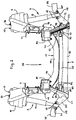
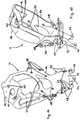
- each strut 6 and 9 is spatially above and laterally outside of the adjacent frame side member 1 or 2 on one the two strut brackets 12 and 13 supported and attached.
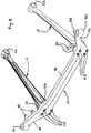
- the two strut holders 12 and 13 together with the crossbar 14 form the - from the front seen - U-shaped cross member 38 according to the invention, the rigid axle body 3rd and bridging the Panhard rod 15 at the top with a small spacing and also connects the two frame side members 1, 2 stabilizing together.
- the cross member 14 by an im Cross-section of hat-shaped pressed metal part, possibly also forged or cast part, formed, which is a straight central section 39 and on both sides thereof, preferably has an obliquely raised end section 40 or 41.
- hat-shaped pressed metal part possibly also forged or cast part, formed, which is a straight central section 39 and on both sides thereof, preferably has an obliquely raised end section 40 or 41.
- whose outer ends are designed in the manner of a mouth with which the one to be connected Suspension strut bracket 12 or 13 is gripped on the outside. Every mouth is through a cutout 42 or 43 in the upper flange of the crossbar 14 and on both sides of each Section 42 and 43 remaining cheeks 44, 45 and 46, 47 formed, which on respective shock absorber bracket 12 or 13 associated front and rear contact surfaces 48, 49 and 50, 51 are assigned.
- the crossbar 14 In the area of these contact surfaces 48, 49 and 50, 51 the crossbar 14 is supported with its cheeks 44, 45 and 46, 47 and there screws 53 penetrating through corresponding bores or holes 52 the respective strut holder 12 or 13 firmly connected. In the middle of his Upper flange, the crossbar 14 to reduce weight one or more Have breakthroughs.
- the two strut brackets 12 and 13 are preferably each by a steel casting realized that after the casting in the required places is finished or finished.
- Each strut holder 12 or 13 is what his As far as shape is concerned, at least in its upper area in the manner of an exterior open half-shell 54 and 55 formed, from the boundary wall 56th or 57 the associated strut 6 or 9 in the area of its air or coil spring 7 or 10 partially covered radially outside with a small distance from the inside is and on the head plate 58 and 59, the respective strut 6 and 9 at the top supported and by means of two holes 60 or 61 penetrating screw connections 62 or 63 is attached.
- a central hole 64 or 65 in the strut head plate 58 or 59 is used to center the respective shock absorber 12 or 13 and free passage from its upper end 36 or 37.
- Each suspension strut bracket 12 or 13 has a height range on the outside of the half-shell 54 or 55 then a connecting flange 66 or 67 with several Screw holes 68 and 69 on.
- the respective connection flange 66 or 67 which is given approximately in the center of thrust, is each of the two strut holders 12 or 13 flanged to the outside of the associated frame side member 1 or 2 and there in each case by means of a plurality of holes 68 and 69, respectively, which are aligned within the longitudinal member Holes penetrating screws 70 attached with associated nuts.
- Different openings 71 and 72 in the strut holders 12 and 13 serve to reduce their weight.
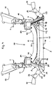
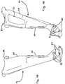
- One of the two strut holders 12 and 13 is about its actual function another function is imprinted, namely that, the frame-side support, Holding and articulating member to form one end of the Panhard rod 15.
- another function is imprinted, namely that, the frame-side support, Holding and articulating member to form one end of the Panhard rod 15.
- the strut holder 12 or 13 down through a bearing plate 73 extended, at the lower end of a mouth and on both sides of the same
- a bearing eye 74 and 75 are formed on each of which the Panhard rod 15 e.g. B. via a claw joint 77 built into its one-end bearing eye 76 and associated screws 78 is attached.
- the Panhard rod 15 is z. B. about a claw joint 80 installed in the bearing eye 79 there at a suitable point of the rigid axle trailing arm assembly.
- a terminal block is preferably formed on it, on which a corresponding contact surface and threaded holes for screwing of the claw joint 80 are worked on.
- this is on this attached or - as shown - co-molded with a protruding laterally inwards Mouth-like bearing block 81 with an outer end face and two internal ones Blind threaded holes provided on which the claw joint 80 can be supported and can be fastened by means of screws 82.
- the essentially straight rod with the bearing eyes forged on the end 76, 79 trained Panhard rod 15 extends due to the as above specified articulation approximately parallel or slightly oblique to the central region 18th of the rigid axle body 3 extending.
- the two multifunction end shields 16, 17 each have one towards the center of the vehicle protruding projection 83 and 84 respectively.
- each the two projections 83, 84 have a pivot point for the rigid axle, namely in the form of a contact surface and a transverse bore 85, in the assembly a bearing bolt penetrating the front trailing arm bearing eye 26 or 27 is installed. Then each of these two bearings from the outside by means of a plurality of screws 86 on the multifunction end shield 16 or 17 attached cover 87 secured.
Landscapes
- Engineering & Computer Science (AREA)
- Mechanical Engineering (AREA)
- Chemical & Material Sciences (AREA)
- Combustion & Propulsion (AREA)
- Transportation (AREA)
- Vehicle Body Suspensions (AREA)
Applications Claiming Priority (2)
| Application Number | Priority Date | Filing Date | Title |
|---|---|---|---|
| DE19809281 | 1998-03-04 | ||
| DE19809281A DE19809281A1 (de) | 1998-03-04 | 1998-03-04 | Fahrgestell eines schweren Nutzfahrzeuges |
Publications (2)
| Publication Number | Publication Date |
|---|---|
| EP0940320A1 true EP0940320A1 (fr) | 1999-09-08 |
| EP0940320B1 EP0940320B1 (fr) | 2003-05-02 |
Family
ID=7859714
Family Applications (1)
| Application Number | Title | Priority Date | Filing Date |
|---|---|---|---|
| EP99101606A Expired - Lifetime EP0940320B1 (fr) | 1998-03-04 | 1999-02-03 | Chassis pour véhicule utilitaire lourd |
Country Status (2)
| Country | Link |
|---|---|
| EP (1) | EP0940320B1 (fr) |
| DE (2) | DE19809281A1 (fr) |
Cited By (6)
| Publication number | Priority date | Publication date | Assignee | Title |
|---|---|---|---|---|
| US6733021B1 (en) | 2001-10-26 | 2004-05-11 | Dana Corporation | Vehicle subframe mounting |
| EP1270282A3 (fr) * | 2001-06-26 | 2004-08-25 | MAN Nutzfahrzeuge Aktiengesellschaft | Essieu composite d'un véhicule utilitaire |
| CN104973135A (zh) * | 2014-04-04 | 2015-10-14 | 蒂森克虏伯钢铁欧洲股份公司 | 弹簧支柱顶部安装件 |
| US9758195B2 (en) | 2014-04-04 | 2017-09-12 | Thyseenkrupp Steel Europe Ag | Spring strut top mounting |
| EP3228485A1 (fr) * | 2016-04-07 | 2017-10-11 | Ford Global Technologies, LLC | Système de suspension d'essieu à barre panhard et véhicule avec système de suspension d'essieu |
| US20230060561A1 (en) * | 2021-08-30 | 2023-03-02 | Monroe Truck Equipment, Inc. | Suspension Mount for an Automotive Vehicle |
Families Citing this family (8)
| Publication number | Priority date | Publication date | Assignee | Title |
|---|---|---|---|---|
| DE10011417B4 (de) * | 2000-03-09 | 2006-01-26 | Daimlerchrysler Ag | Einzelradaufhängung mit radführenden Schräglenkern |
| DE10158107C1 (de) | 2001-11-27 | 2003-02-27 | Daimler Chrysler Ag | Modulartiges Fahrgestell für Nutzfahrzeuge |
| DE10334156A1 (de) | 2003-07-26 | 2005-02-24 | Man Nutzfahrzeuge Ag | Achsaufhängung eines Nutzfahrzeugs |
| DE102005003936B4 (de) * | 2005-01-28 | 2007-05-16 | Daimler Chrysler Ag | Fahrgestellrahmen für ein Nutzfahrzeug |
| DE102008022657A1 (de) | 2008-05-07 | 2009-11-19 | Knorr-Bremse Systeme für Nutzfahrzeuge GmbH | Achsaggregat und Lenker |
| DE102016207518A1 (de) * | 2016-05-02 | 2017-11-02 | Zf Friedrichshafen Ag | Feder-Dämpfermodulanordnung für ein Nutzfahrzeug |
| DE102016207958A1 (de) * | 2016-05-10 | 2017-11-16 | Bayerische Motoren Werke Aktiengesellschaft | Zwei-Rohr-Schwingungsdämpfer für ein Fahrzeug, Fahrzeug mit einem Zwei-Rohr-Schwingungsdämpfer sowie Strömungswiderstandselement für einen Zwei-Rohr-Schwingungsdämpfer |
| CN115432068B (zh) * | 2022-09-30 | 2024-04-12 | 中国重汽集团济南动力有限公司 | 一种轻量化超低位四气囊空气悬架系统 |
Citations (6)
| Publication number | Priority date | Publication date | Assignee | Title |
|---|---|---|---|---|
| US4168086A (en) * | 1977-08-01 | 1979-09-18 | Dana Corporation | Radius arm support for a driving axle |
| DE4226500A1 (de) * | 1992-08-11 | 1994-02-17 | Daimler Benz Ag | Anschlußknoten |
| EP0636531A2 (fr) * | 1993-07-27 | 1995-02-01 | Nissan Motor Co., Ltd. | Structure de véhicule |
| EP0678405A2 (fr) * | 1994-04-18 | 1995-10-25 | Mercedes-Benz Ag | Partie avant d'autobus comprenant un élément porteur pour suspensions élastiques |
| US5641181A (en) * | 1995-03-23 | 1997-06-24 | Ford Motor Company | Cross member for a vehicle having rack and pinion steering |
| DE19624242A1 (de) * | 1996-06-18 | 1997-09-18 | Daimler Benz Ag | Vorrichtung zur Querführung einer Starrachse eines Kraftfahrzeuges |
Family Cites Families (11)
| Publication number | Priority date | Publication date | Assignee | Title |
|---|---|---|---|---|
| DE7728344U1 (de) * | 1977-09-14 | 1978-05-24 | Bergische Achsenfabrik Fr. Kotz & Soehne, 5276 Wiehl | Lenker- und Stabilisatoranordnung für Radachsen von Straßenfahrzeugen |
| DE3706982A1 (de) * | 1986-03-06 | 1987-09-17 | Mazda Motor | Hinterradaufhaengung fuer fahrzeuge |
| US4951962A (en) * | 1986-07-08 | 1990-08-28 | Toyoda Gosei Co., Ltd. | Vibration-proof structure for axle beam of motor vehicle |
| IT1197358B (it) * | 1986-10-07 | 1988-11-30 | Pirelli Accessori Ind | Dispositivo di sospensione per autoveicoli |
| FR2662118A1 (fr) * | 1990-05-17 | 1991-11-22 | Peugeot | Train arriere d'un vehicule automobile. |
| US5518265A (en) * | 1990-08-10 | 1996-05-21 | Benteler Industries, Inc. | Stress equalizing transition twist beam axle |
| CA2081046A1 (fr) * | 1992-03-11 | 1993-09-12 | Robert G. Delbeke | Bras oscillant transversal superieur creux a courbe de resonance amelioree |
| JP3079791B2 (ja) * | 1992-09-11 | 2000-08-21 | 日産自動車株式会社 | 車両用アクスルビーム式サスペンションの配設構造 |
| US5636857A (en) * | 1995-03-06 | 1997-06-10 | Ford Motor Company | Vehicle solid axle front suspension system |
| DE4329862A1 (de) * | 1993-09-03 | 1995-03-09 | Hotzenblitz Mobile Gmbh Co Kg | Hinterachse für Kraftfahrzeuge |
| IT1288797B1 (it) * | 1996-10-31 | 1998-09-24 | Iveco Fiat | Sospensione pneumatica per un assale di un autoveicolo. |
-
1998
- 1998-03-04 DE DE19809281A patent/DE19809281A1/de not_active Withdrawn
-
1999
- 1999-02-03 EP EP99101606A patent/EP0940320B1/fr not_active Expired - Lifetime
- 1999-02-03 DE DE59905271T patent/DE59905271D1/de not_active Expired - Lifetime
Patent Citations (6)
| Publication number | Priority date | Publication date | Assignee | Title |
|---|---|---|---|---|
| US4168086A (en) * | 1977-08-01 | 1979-09-18 | Dana Corporation | Radius arm support for a driving axle |
| DE4226500A1 (de) * | 1992-08-11 | 1994-02-17 | Daimler Benz Ag | Anschlußknoten |
| EP0636531A2 (fr) * | 1993-07-27 | 1995-02-01 | Nissan Motor Co., Ltd. | Structure de véhicule |
| EP0678405A2 (fr) * | 1994-04-18 | 1995-10-25 | Mercedes-Benz Ag | Partie avant d'autobus comprenant un élément porteur pour suspensions élastiques |
| US5641181A (en) * | 1995-03-23 | 1997-06-24 | Ford Motor Company | Cross member for a vehicle having rack and pinion steering |
| DE19624242A1 (de) * | 1996-06-18 | 1997-09-18 | Daimler Benz Ag | Vorrichtung zur Querführung einer Starrachse eines Kraftfahrzeuges |
Cited By (9)
| Publication number | Priority date | Publication date | Assignee | Title |
|---|---|---|---|---|
| EP1270282A3 (fr) * | 2001-06-26 | 2004-08-25 | MAN Nutzfahrzeuge Aktiengesellschaft | Essieu composite d'un véhicule utilitaire |
| US6733021B1 (en) | 2001-10-26 | 2004-05-11 | Dana Corporation | Vehicle subframe mounting |
| WO2003037699A3 (fr) * | 2001-10-26 | 2004-08-12 | Dana Corp | Montage d'un faux cadre de vehicule |
| CN104973135A (zh) * | 2014-04-04 | 2015-10-14 | 蒂森克虏伯钢铁欧洲股份公司 | 弹簧支柱顶部安装件 |
| US9758195B2 (en) | 2014-04-04 | 2017-09-12 | Thyseenkrupp Steel Europe Ag | Spring strut top mounting |
| EP3228485A1 (fr) * | 2016-04-07 | 2017-10-11 | Ford Global Technologies, LLC | Système de suspension d'essieu à barre panhard et véhicule avec système de suspension d'essieu |
| CN107264218A (zh) * | 2016-04-07 | 2017-10-20 | 福特全球技术公司 | 具有横向稳定杆的车轴悬架系统和具有车轴悬架系统的车辆 |
| US20230060561A1 (en) * | 2021-08-30 | 2023-03-02 | Monroe Truck Equipment, Inc. | Suspension Mount for an Automotive Vehicle |
| US11813911B2 (en) * | 2021-08-30 | 2023-11-14 | Monroe Truck Equipment, Inc. | Suspension mount for an automotive vehicle |
Also Published As
| Publication number | Publication date |
|---|---|
| DE59905271D1 (de) | 2003-06-05 |
| DE19809281A1 (de) | 1999-09-09 |
| EP0940320B1 (fr) | 2003-05-02 |
Similar Documents
| Publication | Publication Date | Title |
|---|---|---|
| EP0940272B1 (fr) | Chassis pour un camion à cabine avancée | |
| EP1240065B1 (fr) | Carrosserie automobile comportant un dispositif d'entretoise cote inferieur | |
| DE102013108695B4 (de) | Hilfsrahmen für eine Kraftfahrzeugachse | |
| EP1035003B1 (fr) | Cadre auxiliaire pour un véhicule automobile | |
| DE4204825C2 (de) | Wagenkasten für Kraftfahrzeuge, insbesondere Personenkraftwagen | |
| DE19536460B4 (de) | Teilrahmen für ein Fahrzeug | |
| DE102004028161B4 (de) | Unterfahrschutz für Personenkraftfahrzeuge zur Anordnung unter Längsträgerniveau vor einem Hilfsrahmen oder Achsträger als zusätzliche Crashebene | |
| DE102006062889B4 (de) | Hilfsrahmen, insbesondere für Kraftfahrzeuge | |
| WO2007031060A1 (fr) | Support d'essieu avant destine en particulier a des vehicules | |
| EP0940320B1 (fr) | Chassis pour véhicule utilitaire lourd | |
| DE102009042060A1 (de) | Strukturbauteil für Hinterrahmenstruktur eines Kraftfahrzeugs | |
| EP2114753B1 (fr) | Support d'essieu pour véhicules automobiles | |
| EP0940319B1 (fr) | Chassis d'un véhicule utilitaire lourd | |
| WO2014009320A1 (fr) | Bras de suspension de roue et groupe d'essieu pour un essieu non mené d'un véhicule, notamment d'un véhicule utilitaire | |
| DE69426991T2 (de) | Längsarmaufhängung | |
| EP0940324B1 (fr) | Chassis pour véhicule utilitaire lourd | |
| EP0940322B1 (fr) | Chassis pour véhicule utilitaire lourd | |
| EP0940325B1 (fr) | Chassis pour véhicule utilitaire lourd | |
| EP0940323B1 (fr) | Chassis pour véhicule utilitaire lourd | |
| EP0940321B1 (fr) | Chassis pour véhicule utilitaire lourd | |
| DE102015004858A1 (de) | Lenker für Starrachsen von Nutzfahrzeugen | |
| EP1500530B1 (fr) | Suspension d'essieu rigide pour véhicules avec capture de resort | |
| DE202015102551U1 (de) | Achsanordnung | |
| DE102006010130B4 (de) | Hilfsrahmen, insbesondere für Kraftfahrzeuge | |
| DE102018006572B4 (de) | Fahrzeugaufhängungsanordnung für mindestens eine Radachse |
Legal Events
| Date | Code | Title | Description |
|---|---|---|---|
| PUAI | Public reference made under article 153(3) epc to a published international application that has entered the european phase |
Free format text: ORIGINAL CODE: 0009012 |
|
| 17P | Request for examination filed |
Effective date: 19990714 |
|
| AK | Designated contracting states |
Kind code of ref document: A1 Designated state(s): DE FR IT NL SE |
|
| AX | Request for extension of the european patent |
Free format text: AL;LT;LV;MK;RO;SI |
|
| AKX | Designation fees paid |
Free format text: DE FR IT NL SE |
|
| 17Q | First examination report despatched |
Effective date: 20010716 |
|
| GRAG | Despatch of communication of intention to grant |
Free format text: ORIGINAL CODE: EPIDOS AGRA |
|
| GRAG | Despatch of communication of intention to grant |
Free format text: ORIGINAL CODE: EPIDOS AGRA |
|
| GRAH | Despatch of communication of intention to grant a patent |
Free format text: ORIGINAL CODE: EPIDOS IGRA |
|
| GRAH | Despatch of communication of intention to grant a patent |
Free format text: ORIGINAL CODE: EPIDOS IGRA |
|
| GRAA | (expected) grant |
Free format text: ORIGINAL CODE: 0009210 |
|
| AK | Designated contracting states |
Designated state(s): DE FR IT NL SE |
|
| REF | Corresponds to: |
Ref document number: 59905271 Country of ref document: DE Date of ref document: 20030605 Kind code of ref document: P |
|
| REG | Reference to a national code |
Ref country code: SE Ref legal event code: TRGR |
|
| ET | Fr: translation filed | ||
| PLBE | No opposition filed within time limit |
Free format text: ORIGINAL CODE: 0009261 |
|
| STAA | Information on the status of an ep patent application or granted ep patent |
Free format text: STATUS: NO OPPOSITION FILED WITHIN TIME LIMIT |
|
| 26N | No opposition filed |
Effective date: 20040203 |
|
| REG | Reference to a national code |
Ref country code: NL Ref legal event code: TD Effective date: 20110420 |
|
| REG | Reference to a national code |
Ref country code: FR Ref legal event code: CD |
|
| REG | Reference to a national code |
Ref country code: DE Ref legal event code: R081 Ref document number: 59905271 Country of ref document: DE Owner name: MAN TRUCK & BUS AG, DE Free format text: FORMER OWNER: MAN NUTZFAHRZEUGE AG, 80995 MUENCHEN, DE Effective date: 20110518 |
|
| REG | Reference to a national code |
Ref country code: FR Ref legal event code: PLFP Year of fee payment: 18 |
|
| REG | Reference to a national code |
Ref country code: FR Ref legal event code: PLFP Year of fee payment: 19 |
|
| REG | Reference to a national code |
Ref country code: FR Ref legal event code: PLFP Year of fee payment: 20 |
|
| PGFP | Annual fee paid to national office [announced via postgrant information from national office to epo] |
Ref country code: NL Payment date: 20180223 Year of fee payment: 20 |
|
| PGFP | Annual fee paid to national office [announced via postgrant information from national office to epo] |
Ref country code: FR Payment date: 20180227 Year of fee payment: 20 Ref country code: SE Payment date: 20180227 Year of fee payment: 20 Ref country code: IT Payment date: 20180221 Year of fee payment: 20 |
|
| PGFP | Annual fee paid to national office [announced via postgrant information from national office to epo] |
Ref country code: DE Payment date: 20180430 Year of fee payment: 20 |
|
| REG | Reference to a national code |
Ref country code: DE Ref legal event code: R071 Ref document number: 59905271 Country of ref document: DE |
|
| REG | Reference to a national code |
Ref country code: NL Ref legal event code: MK Effective date: 20190202 |
|
| REG | Reference to a national code |
Ref country code: SE Ref legal event code: EUG |