EP0528219A2 - Kompositstrukturen und Wasserleitstrukturen für Schiffe - Google Patents
Kompositstrukturen und Wasserleitstrukturen für Schiffe Download PDFInfo
- Publication number
- EP0528219A2 EP0528219A2 EP92112909A EP92112909A EP0528219A2 EP 0528219 A2 EP0528219 A2 EP 0528219A2 EP 92112909 A EP92112909 A EP 92112909A EP 92112909 A EP92112909 A EP 92112909A EP 0528219 A2 EP0528219 A2 EP 0528219A2
- Authority
- EP
- European Patent Office
- Prior art keywords
- layers
- elastomeric
- laminate
- vanes
- vibration
- Prior art date
- Legal status (The legal status is an assumption and is not a legal conclusion. Google has not performed a legal analysis and makes no representation as to the accuracy of the status listed.)
- Granted
Links
Images








Classifications
-
- B—PERFORMING OPERATIONS; TRANSPORTING
- B32—LAYERED PRODUCTS
- B32B—LAYERED PRODUCTS, i.e. PRODUCTS BUILT-UP OF STRATA OF FLAT OR NON-FLAT, e.g. CELLULAR OR HONEYCOMB, FORM
- B32B1/00—Layered products having a non-planar shape
-
- B—PERFORMING OPERATIONS; TRANSPORTING
- B32—LAYERED PRODUCTS
- B32B—LAYERED PRODUCTS, i.e. PRODUCTS BUILT-UP OF STRATA OF FLAT OR NON-FLAT, e.g. CELLULAR OR HONEYCOMB, FORM
- B32B25/00—Layered products comprising a layer of natural or synthetic rubber
- B32B25/04—Layered products comprising a layer of natural or synthetic rubber comprising rubber as the main or only constituent of a layer, which is next to another layer of the same or of a different material
-
- B—PERFORMING OPERATIONS; TRANSPORTING
- B32—LAYERED PRODUCTS
- B32B—LAYERED PRODUCTS, i.e. PRODUCTS BUILT-UP OF STRATA OF FLAT OR NON-FLAT, e.g. CELLULAR OR HONEYCOMB, FORM
- B32B25/00—Layered products comprising a layer of natural or synthetic rubber
- B32B25/04—Layered products comprising a layer of natural or synthetic rubber comprising rubber as the main or only constituent of a layer, which is next to another layer of the same or of a different material
- B32B25/08—Layered products comprising a layer of natural or synthetic rubber comprising rubber as the main or only constituent of a layer, which is next to another layer of the same or of a different material of synthetic resin
-
- B—PERFORMING OPERATIONS; TRANSPORTING
- B32—LAYERED PRODUCTS
- B32B—LAYERED PRODUCTS, i.e. PRODUCTS BUILT-UP OF STRATA OF FLAT OR NON-FLAT, e.g. CELLULAR OR HONEYCOMB, FORM
- B32B25/00—Layered products comprising a layer of natural or synthetic rubber
- B32B25/12—Layered products comprising a layer of natural or synthetic rubber comprising natural rubber
-
- B—PERFORMING OPERATIONS; TRANSPORTING
- B32—LAYERED PRODUCTS
- B32B—LAYERED PRODUCTS, i.e. PRODUCTS BUILT-UP OF STRATA OF FLAT OR NON-FLAT, e.g. CELLULAR OR HONEYCOMB, FORM
- B32B25/00—Layered products comprising a layer of natural or synthetic rubber
- B32B25/18—Layered products comprising a layer of natural or synthetic rubber comprising butyl or halobutyl rubber
-
- B—PERFORMING OPERATIONS; TRANSPORTING
- B32—LAYERED PRODUCTS
- B32B—LAYERED PRODUCTS, i.e. PRODUCTS BUILT-UP OF STRATA OF FLAT OR NON-FLAT, e.g. CELLULAR OR HONEYCOMB, FORM
- B32B25/00—Layered products comprising a layer of natural or synthetic rubber
- B32B25/20—Layered products comprising a layer of natural or synthetic rubber comprising silicone rubber
-
- B—PERFORMING OPERATIONS; TRANSPORTING
- B32—LAYERED PRODUCTS
- B32B—LAYERED PRODUCTS, i.e. PRODUCTS BUILT-UP OF STRATA OF FLAT OR NON-FLAT, e.g. CELLULAR OR HONEYCOMB, FORM
- B32B27/00—Layered products comprising a layer of synthetic resin
- B32B27/06—Layered products comprising a layer of synthetic resin as the main or only constituent of a layer, which is next to another layer of the same or of a different material
- B32B27/08—Layered products comprising a layer of synthetic resin as the main or only constituent of a layer, which is next to another layer of the same or of a different material of synthetic resin
-
- B—PERFORMING OPERATIONS; TRANSPORTING
- B32—LAYERED PRODUCTS
- B32B—LAYERED PRODUCTS, i.e. PRODUCTS BUILT-UP OF STRATA OF FLAT OR NON-FLAT, e.g. CELLULAR OR HONEYCOMB, FORM
- B32B27/00—Layered products comprising a layer of synthetic resin
- B32B27/30—Layered products comprising a layer of synthetic resin comprising vinyl (co)polymers; comprising acrylic (co)polymers
- B32B27/302—Layered products comprising a layer of synthetic resin comprising vinyl (co)polymers; comprising acrylic (co)polymers comprising aromatic vinyl (co)polymers, e.g. styrenic (co)polymers
-
- B—PERFORMING OPERATIONS; TRANSPORTING
- B32—LAYERED PRODUCTS
- B32B—LAYERED PRODUCTS, i.e. PRODUCTS BUILT-UP OF STRATA OF FLAT OR NON-FLAT, e.g. CELLULAR OR HONEYCOMB, FORM
- B32B27/00—Layered products comprising a layer of synthetic resin
- B32B27/30—Layered products comprising a layer of synthetic resin comprising vinyl (co)polymers; comprising acrylic (co)polymers
- B32B27/308—Layered products comprising a layer of synthetic resin comprising vinyl (co)polymers; comprising acrylic (co)polymers comprising acrylic (co)polymers
-
- B—PERFORMING OPERATIONS; TRANSPORTING
- B32—LAYERED PRODUCTS
- B32B—LAYERED PRODUCTS, i.e. PRODUCTS BUILT-UP OF STRATA OF FLAT OR NON-FLAT, e.g. CELLULAR OR HONEYCOMB, FORM
- B32B27/00—Layered products comprising a layer of synthetic resin
- B32B27/38—Layered products comprising a layer of synthetic resin comprising epoxy resins
-
- B—PERFORMING OPERATIONS; TRANSPORTING
- B63—SHIPS OR OTHER WATERBORNE VESSELS; RELATED EQUIPMENT
- B63B—SHIPS OR OTHER WATERBORNE VESSELS; EQUIPMENT FOR SHIPPING
- B63B3/00—Hulls characterised by their structure or component parts
- B63B3/14—Hull parts
- B63B3/42—Shaft brackets
-
- B—PERFORMING OPERATIONS; TRANSPORTING
- B63—SHIPS OR OTHER WATERBORNE VESSELS; RELATED EQUIPMENT
- B63B—SHIPS OR OTHER WATERBORNE VESSELS; EQUIPMENT FOR SHIPPING
- B63B3/00—Hulls characterised by their structure or component parts
- B63B3/14—Hull parts
- B63B3/68—Panellings; Linings, e.g. for insulating purposes
-
- B—PERFORMING OPERATIONS; TRANSPORTING
- B63—SHIPS OR OTHER WATERBORNE VESSELS; RELATED EQUIPMENT
- B63B—SHIPS OR OTHER WATERBORNE VESSELS; EQUIPMENT FOR SHIPPING
- B63B5/00—Hulls characterised by their construction of non-metallic material
- B63B5/24—Hulls characterised by their construction of non-metallic material made predominantly of plastics
-
- B—PERFORMING OPERATIONS; TRANSPORTING
- B63—SHIPS OR OTHER WATERBORNE VESSELS; RELATED EQUIPMENT
- B63H—MARINE PROPULSION OR STEERING
- B63H21/00—Use of propulsion power plant or units on vessels
- B63H21/30—Mounting of propulsion plant or unit, e.g. for anti-vibration purposes
- B63H21/305—Mounting of propulsion plant or unit, e.g. for anti-vibration purposes with passive vibration damping
-
- B—PERFORMING OPERATIONS; TRANSPORTING
- B63—SHIPS OR OTHER WATERBORNE VESSELS; RELATED EQUIPMENT
- B63H—MARINE PROPULSION OR STEERING
- B63H23/00—Transmitting power from propulsion power plant to propulsive elements
- B63H23/32—Other parts
- B63H23/321—Bearings or seals specially adapted for propeller shafts
- B63H23/326—Water lubricated bearings
-
- F—MECHANICAL ENGINEERING; LIGHTING; HEATING; WEAPONS; BLASTING
- F16—ENGINEERING ELEMENTS AND UNITS; GENERAL MEASURES FOR PRODUCING AND MAINTAINING EFFECTIVE FUNCTIONING OF MACHINES OR INSTALLATIONS; THERMAL INSULATION IN GENERAL
- F16C—SHAFTS; FLEXIBLE SHAFTS; ELEMENTS OR CRANKSHAFT MECHANISMS; ROTARY BODIES OTHER THAN GEARING ELEMENTS; BEARINGS
- F16C17/00—Sliding-contact bearings for exclusively rotary movement
- F16C17/12—Sliding-contact bearings for exclusively rotary movement characterised by features not related to the direction of the load
- F16C17/14—Sliding-contact bearings for exclusively rotary movement characterised by features not related to the direction of the load specially adapted for operating in water
-
- F—MECHANICAL ENGINEERING; LIGHTING; HEATING; WEAPONS; BLASTING
- F16—ENGINEERING ELEMENTS AND UNITS; GENERAL MEASURES FOR PRODUCING AND MAINTAINING EFFECTIVE FUNCTIONING OF MACHINES OR INSTALLATIONS; THERMAL INSULATION IN GENERAL
- F16C—SHAFTS; FLEXIBLE SHAFTS; ELEMENTS OR CRANKSHAFT MECHANISMS; ROTARY BODIES OTHER THAN GEARING ELEMENTS; BEARINGS
- F16C33/00—Parts of bearings; Special methods for making bearings or parts thereof
- F16C33/02—Parts of sliding-contact bearings
- F16C33/04—Brasses; Bushes; Linings
- F16C33/26—Brasses; Bushes; Linings made from wire coils; made from a number of discs, rings, rods, or other members
-
- F—MECHANICAL ENGINEERING; LIGHTING; HEATING; WEAPONS; BLASTING
- F16—ENGINEERING ELEMENTS AND UNITS; GENERAL MEASURES FOR PRODUCING AND MAINTAINING EFFECTIVE FUNCTIONING OF MACHINES OR INSTALLATIONS; THERMAL INSULATION IN GENERAL
- F16D—COUPLINGS FOR TRANSMITTING ROTATION; CLUTCHES; BRAKES
- F16D3/00—Yielding couplings, i.e. with means permitting movement between the connected parts during the drive
- F16D3/50—Yielding couplings, i.e. with means permitting movement between the connected parts during the drive with the coupling parts connected by one or more intermediate members
-
- B—PERFORMING OPERATIONS; TRANSPORTING
- B32—LAYERED PRODUCTS
- B32B—LAYERED PRODUCTS, i.e. PRODUCTS BUILT-UP OF STRATA OF FLAT OR NON-FLAT, e.g. CELLULAR OR HONEYCOMB, FORM
- B32B2605/00—Vehicles
- B32B2605/12—Ships
-
- F—MECHANICAL ENGINEERING; LIGHTING; HEATING; WEAPONS; BLASTING
- F16—ENGINEERING ELEMENTS AND UNITS; GENERAL MEASURES FOR PRODUCING AND MAINTAINING EFFECTIVE FUNCTIONING OF MACHINES OR INSTALLATIONS; THERMAL INSULATION IN GENERAL
- F16C—SHAFTS; FLEXIBLE SHAFTS; ELEMENTS OR CRANKSHAFT MECHANISMS; ROTARY BODIES OTHER THAN GEARING ELEMENTS; BEARINGS
- F16C2326/00—Articles relating to transporting
- F16C2326/30—Ships, e.g. propelling shafts and bearings therefor
-
- Y—GENERAL TAGGING OF NEW TECHNOLOGICAL DEVELOPMENTS; GENERAL TAGGING OF CROSS-SECTIONAL TECHNOLOGIES SPANNING OVER SEVERAL SECTIONS OF THE IPC; TECHNICAL SUBJECTS COVERED BY FORMER USPC CROSS-REFERENCE ART COLLECTIONS [XRACs] AND DIGESTS
- Y10—TECHNICAL SUBJECTS COVERED BY FORMER USPC
- Y10T—TECHNICAL SUBJECTS COVERED BY FORMER US CLASSIFICATION
- Y10T403/00—Joints and connections
- Y10T403/57—Distinct end coupler
- Y10T403/5761—Interrupted periphery, e.g., split or segmental, etc.
- Y10T403/5766—Axially divided segments
- Y10T403/5781—Bolted
-
- Y—GENERAL TAGGING OF NEW TECHNOLOGICAL DEVELOPMENTS; GENERAL TAGGING OF CROSS-SECTIONAL TECHNOLOGIES SPANNING OVER SEVERAL SECTIONS OF THE IPC; TECHNICAL SUBJECTS COVERED BY FORMER USPC CROSS-REFERENCE ART COLLECTIONS [XRACs] AND DIGESTS
- Y10—TECHNICAL SUBJECTS COVERED BY FORMER USPC
- Y10T—TECHNICAL SUBJECTS COVERED BY FORMER US CLASSIFICATION
- Y10T428/00—Stock material or miscellaneous articles
- Y10T428/13—Hollow or container type article [e.g., tube, vase, etc.]
- Y10T428/1352—Polymer or resin containing [i.e., natural or synthetic]
-
- Y—GENERAL TAGGING OF NEW TECHNOLOGICAL DEVELOPMENTS; GENERAL TAGGING OF CROSS-SECTIONAL TECHNOLOGIES SPANNING OVER SEVERAL SECTIONS OF THE IPC; TECHNICAL SUBJECTS COVERED BY FORMER USPC CROSS-REFERENCE ART COLLECTIONS [XRACs] AND DIGESTS
- Y10—TECHNICAL SUBJECTS COVERED BY FORMER USPC
- Y10T—TECHNICAL SUBJECTS COVERED BY FORMER US CLASSIFICATION
- Y10T428/00—Stock material or miscellaneous articles
- Y10T428/13—Hollow or container type article [e.g., tube, vase, etc.]
- Y10T428/1352—Polymer or resin containing [i.e., natural or synthetic]
- Y10T428/1355—Elemental metal containing [e.g., substrate, foil, film, coating, etc.]
- Y10T428/1359—Three or more layers [continuous layer]
-
- Y—GENERAL TAGGING OF NEW TECHNOLOGICAL DEVELOPMENTS; GENERAL TAGGING OF CROSS-SECTIONAL TECHNOLOGIES SPANNING OVER SEVERAL SECTIONS OF THE IPC; TECHNICAL SUBJECTS COVERED BY FORMER USPC CROSS-REFERENCE ART COLLECTIONS [XRACs] AND DIGESTS
- Y10—TECHNICAL SUBJECTS COVERED BY FORMER USPC
- Y10T—TECHNICAL SUBJECTS COVERED BY FORMER US CLASSIFICATION
- Y10T428/00—Stock material or miscellaneous articles
- Y10T428/13—Hollow or container type article [e.g., tube, vase, etc.]
- Y10T428/1352—Polymer or resin containing [i.e., natural or synthetic]
- Y10T428/1372—Randomly noninterengaged or randomly contacting fibers, filaments, particles, or flakes
-
- Y—GENERAL TAGGING OF NEW TECHNOLOGICAL DEVELOPMENTS; GENERAL TAGGING OF CROSS-SECTIONAL TECHNOLOGIES SPANNING OVER SEVERAL SECTIONS OF THE IPC; TECHNICAL SUBJECTS COVERED BY FORMER USPC CROSS-REFERENCE ART COLLECTIONS [XRACs] AND DIGESTS
- Y10—TECHNICAL SUBJECTS COVERED BY FORMER USPC
- Y10T—TECHNICAL SUBJECTS COVERED BY FORMER US CLASSIFICATION
- Y10T428/00—Stock material or miscellaneous articles
- Y10T428/31504—Composite [nonstructural laminate]
- Y10T428/31511—Of epoxy ether
-
- Y—GENERAL TAGGING OF NEW TECHNOLOGICAL DEVELOPMENTS; GENERAL TAGGING OF CROSS-SECTIONAL TECHNOLOGIES SPANNING OVER SEVERAL SECTIONS OF THE IPC; TECHNICAL SUBJECTS COVERED BY FORMER USPC CROSS-REFERENCE ART COLLECTIONS [XRACs] AND DIGESTS
- Y10—TECHNICAL SUBJECTS COVERED BY FORMER USPC
- Y10T—TECHNICAL SUBJECTS COVERED BY FORMER US CLASSIFICATION
- Y10T428/00—Stock material or miscellaneous articles
- Y10T428/31504—Composite [nonstructural laminate]
- Y10T428/31786—Of polyester [e.g., alkyd, etc.]
-
- Y—GENERAL TAGGING OF NEW TECHNOLOGICAL DEVELOPMENTS; GENERAL TAGGING OF CROSS-SECTIONAL TECHNOLOGIES SPANNING OVER SEVERAL SECTIONS OF THE IPC; TECHNICAL SUBJECTS COVERED BY FORMER USPC CROSS-REFERENCE ART COLLECTIONS [XRACs] AND DIGESTS
- Y10—TECHNICAL SUBJECTS COVERED BY FORMER USPC
- Y10T—TECHNICAL SUBJECTS COVERED BY FORMER US CLASSIFICATION
- Y10T428/00—Stock material or miscellaneous articles
- Y10T428/31504—Composite [nonstructural laminate]
- Y10T428/31855—Of addition polymer from unsaturated monomers
- Y10T428/31909—Next to second addition polymer from unsaturated monomers
- Y10T428/31913—Monoolefin polymer
- Y10T428/31917—Next to polyene polymer
-
- Y—GENERAL TAGGING OF NEW TECHNOLOGICAL DEVELOPMENTS; GENERAL TAGGING OF CROSS-SECTIONAL TECHNOLOGIES SPANNING OVER SEVERAL SECTIONS OF THE IPC; TECHNICAL SUBJECTS COVERED BY FORMER USPC CROSS-REFERENCE ART COLLECTIONS [XRACs] AND DIGESTS
- Y10—TECHNICAL SUBJECTS COVERED BY FORMER USPC
- Y10T—TECHNICAL SUBJECTS COVERED BY FORMER US CLASSIFICATION
- Y10T428/00—Stock material or miscellaneous articles
- Y10T428/31504—Composite [nonstructural laminate]
- Y10T428/31855—Of addition polymer from unsaturated monomers
- Y10T428/31909—Next to second addition polymer from unsaturated monomers
- Y10T428/31913—Monoolefin polymer
- Y10T428/3192—Next to vinyl or vinylidene chloride polymer
Definitions
- This invention relates to propulsion shaft supports for marine vessels and more particularly to a new and improved means including a composite structure for fairing and protecting propeller shaft, strut barrels, and its bearings in a marine environment while providing a unique means to force lubricate and/or cool the bearings for such shaft while preventing marine-fouling and reducing vibration.
- the composite structure is of a laminate or sandwiched construction which is cavitation-resistant, anti-fouling and vibration-dampening.
- Such composite can be formed or molded into various sizes and shapes to facilitate its application to a marine environment such as underwater ship structures and the like.
- the propulsion shaft of a marine vessel extends a considerable distance aft or to the stern from its exit position from such vessel or ship and requires a plurality of support points along such extension of the shaft to assure support of the shafts over hung load and stability as it rotates. On many vessels there may be up to three or four support points along its entire length that need support.
- the conventional strut supports for supporting the bearings and the coupling of the rotating shaft would include a metal housing or fairwater that encompasses these elements.
- the metal housing has a vertical extending support or strut whose upper portions is suitably connected to the vessel framework to provide stability to the support structure.
- the fairwater structure and strut supports are metallic in nature wherein such housings or fairwater structures are two hemispheres that are clamped onto the coupling of the drive shaft while desirably having a hydrodynamically balanced shape to reduce turbulence in that area.
- Such housings since in dealing with metal, take the shapes of cylinders and portions of spheres to enhance their handling and manufacture. Considerable shaping and welding and rewelding is required in the manufacture of such housings, which in effect are not ideally hydrodynamic in shape.
- the present invention solves these problems and provides other advantages by providing a composite structure that can be molded into optimal hydrodynamic shapes while insuring durability. Further a cover or casing is attached to the drive shaft forwardly of the bearing structure with pumping vanes mounted thereon. The fairwater structure is then mounted over such cover and attached to the bearing housing to provide a clearance space therebetween so that as the drive shaft is rotated, the vanes will force water through the bearing structure to cool the shaft while providing lubricant to the bearing.
- such combination of the cover, pumping vanes and fairwater structure can be used on a coupling that joins axially aligned drive shafts for the propeller to enhance the hydrodynamic flow of water thereover and therethrough.
- such fairwater structure enhances serviceability while insuring the forced flow of the surrounding fluids through the bearing structure even when the drive shaft is at an idle speed and the propeller blades are feathered.
- the invention is directed to a bearing assembly and a coupling for a drive shaft of a marine vessel wherein the coupling has a coupling cover encompassing it and secured to the shaft with a fairwater further encompassing the coupling cover and secured to the bearing assembly.
- a plurality of vanes are either mounted on the coupling cover or on a separate support that is attached to the shaft between the coupling cover and the bearing assembly to direct the flow of fluids along the clearance space between the coupling cover and the fairwater to lubricate the staves in the bearing assembly.
- the housings of the bearing assembly, the coupling cover, the vanes and related accessories are molded from the new and improved composite to provide an impact and abrasion resistant, corrosion and cavitation-resistant, anti-fouling, self-dampening, light weight parts. This permits repair and easy removing of the parts under water.
- a further object of this invention is to provide a marine composite which can be efficiently and economically manufactured.
- Figs. 1 and 2 a pair of longitudinally extending propeller shafts or drive shafts 10 and 11, each supported by brackets or struts 12-14, which struts are themselves depending from and are suitably attached to ships hull 15.
- the shafts 10 and 11 have separate axial center lines and are similarly constructed and only shaft 10 will be described.
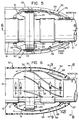
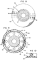
- Shaft 10 is composed of axially aligned shaft sections or drive shafts 16, 17 and 18 interconnected by couplings 19 as more specifically shown in Figs. 3, 5 and 6. All couplings are similar and only the coupling for adjacent end portions of shafts 17 and 18 will be described.
- shaft sections 17 and 18 have circular flanges 21 and 22 respectively which are secured together as by bolts 23 or by other suitable means.
- the one exposed end portion of shaft 16 extends into the hull 15 of the ship through a suitable stuffing box 24 for connection to the engine of the ship.
- Each shaft 10 and 11 have variably pitched propellers 26 and 27 respectively suitably mounted on their respective ends.
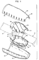
- the flanges 21 and 22 are covered by a pair of shell halves (Fig. 11) 28 and 29, joined together by suitable bolts.
- the shell halves 28 and 29 at the respective ends are recessed to closely encompass and frictionally engage shafts 17 and 18 close to the abutting ends of such shafts and their flanges 21 and 22.
- An annular gasket 31 may be interposed between the shaft sections 17 and 18 and the respective end portions of such shell halves 28, 29 to provide a sealed chamber to receive a suitable filler or preservative.
- the general contour of such joined shell halves 28 and 29 is generally ellipsoidal or oval shaped to define a support or coupling cover or casing 30. Although reference is ellipsoidal, other shapes are contemplated as discussed hereinafter.
- the coupling cover or housing 30 is firmly secured to the respective shaft sections 17 and 18 to rotate with them.
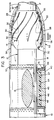
- the coupling cover has a plurality of circumferentially spaced vanes 32 mounted on the outer surface thereof in a spiral or helical path relative to the longitudinal center line or axial center line of the shaft 10.
- the vanes 32 are solid and can be molded with the molding of the shell halves 28 and 29 or molded separately and suitably attached to such shell halves.
- a vane is a thin flat or curved object that is made to rotate about an axis to cause a fluid to flow or that redirects a flow of fluid.
- the vanes can be helical as shown in Fig. 3 or a series of flat thin members as disclosed in Fig. 23.
- housing or strut barrel 40 mounted by a strut 13.
- Housing or strut barrel 40 has a pair of spaced annular end surfaces 42 (Fig. 4), with threaded bores 43 extending into the housing.
- the housing 40 has a central opening or bore 44 with a central axis to accommodate a bearing unit to be described.
- the bearing unit has an outer cylindrical shell 45 which receives a plurality of circumferentially spaced bearing staves 46.
- Each stave 46 includes a rectangular bearing support element or backing support 47 made from a high quality non-corroding, ultra high molecular weight polyethylene.
- Suitably bonded to each support bearing element 47 is an elastomeric bearing element 48.
- the bearing housing, the cylindrical shell 45 and the staves define a bearing assembly that is supported by the strut 13, which strut may be integral with the bearing housing or suitably attached to it.
- An elastomer is defined as a substance that can be stretched at room temperatures to at least twice its original length and, after having been stretched and the stress removed, returns with force to approximately its original length in a short time (see Glossary of Terms as prepared by ASTM Committee D11 on Rubber and Rubberlike Materials published by the American Society for Testing Materials).
- the elastomeric or rubber material that can be used can be any of the well known elastomers including for example natural rubber, copolymers of butadiene and acrylonitrile, copolymers of butadiene and styrene, copolymers of butadiene and alkyl acrylates, butyl rubber, olefin rubbers such as ethylene-propylene and EPDM rubber, fluorocarbon rubbers, fluorosilicone rubbers, silicone rubbers, chlorosulfonated polyethylene, polyacrylates, polybutadiene, polychloroprene and the like.
- the outer shell 45 and the staves 46 are located within such central bore 44 of the housing 40 such that the respective ends abut a pair of semicircular retainer rings 49 which are secured to the end sections of the housing 40.
- Rings 49 have a plurality of circumferentially spaced bores which receive bolts 51 which in turn are threaded into the respective threaded bores 43 to securely fasten the bearing units within housing 40 with the respective staves 46 surrounding and supporting the propeller shafts 10.
- the staves 46 have a clearance space between adjacent ones defining a plurality of circumferentially spaced grooves to insure a proper flow of water for lubricating the rubber bearing surfaces as well as cool the bearing assembly.
- the respective staves 46 are replaceable and are easily accessible by the removal of retainer rings 49.
- a metal oval shaped housing, shell, cover or fairwater nose 53 composed of two half shell sections 54 and 55 (Figs. 1 and 4) are suitably secured together by bolts 56.
- the one end of fairwater nose 53 is suitably connected to the retainer ring 50 or bearing housing 40 to permit selective detachment for inspection of the bearings and maintenance thereof.
- the other end portion of fairwater 53 tapers downwardly over the coupling cover 30 to provide an annular clearance space 57 between such fairwater and the outer peripheral surface of shaft section 17.
- the general outer and inner shape or contour of fairwater 53 is to the general outer ellipsoidal shape of the coupling cover 30 as depicted by Fig.
- the interior or fairwater 61 has a smooth contour that directs the flow of water away from the fairwater 53 and the bearing assembly 40 outwardly therefrom to maintain a smooth flow path.
- the fairwater 53 is referred to as the fairwater nose while the fairwater 61 is referred to as the fairwater tail.
- Fig. 11 discloses in phantom lines the axially aligned shaft sections 17 and 18 fastened together by a coupling 19, which coupling 19 has a pair of half shells 28 and 29 securely fastened to the shaft sections to provide a rotating coupling cover 30 with helical vanes 32 thereon, which in turn is encompassed by a fairwater 53 composed of two half shell sections 54 and 55.
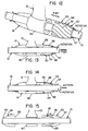
- FIG. 16 discloses a coupling cover, designated 64, having a plurality of vanes or fins 65 suitably connected to the upstream or rearwardly disposed portion of such coupling cover 64.
- Such fins are made from a flexible elastomeric compound to permit a slight flexing thereof in accordance with the direction of rotation of the shaft sections.
- the cover is generally cylindrical for the major portion of its axial length and tapers sharply as at 66 on its rearward portion to closely encompass and frictionally engage the shaft sections and to be suitably secured thereto to ensure simultaneous rotation therewith.
- a fairwater or cover 68 encompasses the coupling cover 64 and is attached to the bearing assembly 40 while providing an annular clearance space between its interior surface and the coupling cover 64 while terminating at its forwardly disposed position with a clearance space around shaft section 17 to insure a proper flow of lubricant fluids.
- This modification as well as other modifications are described with respect to shaft sections 17 and 18 and their coupling 19 for simplicity are equally applicable to other shaft sections or to wherever a supporting strut may be required. In certain instances where a strut and bearing assembly is used to support a shaft section, a coupling cover may be used even though a coupling is absent so that the function is to provide the means for lubricating the staves of a bearing assembly.
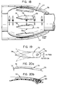
- FIG. 18 A further modification of the invention is shown in Figs. 18, 19 and 20 and which discloses a coupling cover designated 71.
- Cover 71 is substantially identical in construction and contour to the rotating coupling cover 30 described in the first embodiment of Figs. 3 through 6 except that the vanes 72 on cover 71 are made from a flexible elastomeric compound that may have fabric reinforcing them or, if desired, a stiffening rib embedded therein to give the vane 72 some stiffness, yet permitting flexing thereof as shown in Fig. 19.
- Vanes 72 are in effect flexible vanes in comparison to the fixed vanes of the first embodiment (vanes 32).
- Vanes 72 are oblong in shape in plan view having a rounded forward end 73 and a rearwardly disposed tapering end 74.
- the forwardly disposed end 73 of vane 72 has a greater thickness than the remaining portion of the vanes to provide a clearance space indicated as "A" in Fig. 20 (as viewed in side elevation) to facilitate the deflection of the rearwardly disposed portion 74 to permit its pumping of water as the coupling cover 71 rotates in either direction.
- the forwardly disposed end portion 73 is suitably and firmly secured to the coupling cover, which in Fig. 19 is shown as a threaded bolt 75. More than one bolt may be used to assure the alignment of the vanes 72 on coupling cover 71.
- the coupling cover 71 is encompassed by a fairwater 76 to provide an annular clearance space 77 for the passage of water between such fairwater 76 and the outer surface of coupling cover 71 to provide lubricant to the bearing assembly as previously described.
- a further modification of this invention would be to have the fins 72 of rigid material and have an elastomeric connection in lieu of the threaded bolt 75 to thus allow the rigid vane to yield at its elastomeric connection which in effect would act as a torsion spring as illustrated in Fig. 20b.
- the fin 72' is illustrated as secured to an elastomeric bushing 69 that is square in plan view, and which bushing 69 is bonded to a hex or square threaded bushing 70 to provide means for securing it to a coupling cover.
- the elastomeric bushing 69 with its interconnection to the coupling cover and the fin 72' acts as a torsion spring.
- FIGs. 21 through 25 discloses a coupling cover 80 similar in contour to the coupling cover 64 of Fig. 16 although any hydrodynamically contoured shape is contemplated including that of Fig. 6.
- Upstream of the coupling cover 80 is the bearing housing 40 containing its staves as previously described.
- Encompassing the coupling cover 80 and suitably attached to bearing housing 40 is a fairwater or outer shell 81 having a forwardly disposed hemispherical portion 82 and a longitudinally extending cylindrical portion 83 to define a chamber 84 therebetween.
- the contour of the fairwater 81 follows the general contour of the coupling cover 80 to define an annular clearance space 58 therebetween to facilitate the flow of water into chamber 84 for lubricating the staves of the adjacent bearing assembly within bearing housing 40.
- the forwardly disposed end of hemispherical portion 82 closely encompasses the drive shaft to permit the flow of water into chamber 84.
- a hub 85 Located between bearing housing 40 and the coupling cover 80 is a hub 85, composed of two half sections containing inner rim portions 86, 87 and outer rim portions 88, 89.
- the inner rim half portions 86, 87 are secured to the outer rim half portions 88, 89 by radially extending members that are interconnected by suitable bolts to form such hub 85 that frictionally engages the outer peripheral surface of shaft section 18 to insure rotation therewith.
- a plurality of circumferentially spaced elastomeric vanes 90 are suitably secured between the inner rim portions 86, 87 and the outer rim portions 88, 89.
- the vanes 90 may be constructed of an elastomeric compound with or without fabric reinforcing elements to restrict the flexibility of their deflection.
- the cross-sectional plan view of each vane 90 has one end of a rounded configuration as at 91 whose respective sides taper to an apex 92. As seen in Fig.
- the respective vanes in this embodiment are molded integrally with the inner and outer rim sections 86, 87 and 88, 89 respectively.
- the vanes 90 In the normal stationary condition of such hub 85 as mounted on the shaft section 18, the vanes 90 have their apexes 92 disposed along planes that pass through the axial center line (designated B in Fig. 22).
- the vanes will deflect to provide a pumping action to the water contained in the chamber 84 through the bearing assembly to lubricate the staves.
- the hub 85 with its vanes 90 located between the coupling cover 80 and the bearing housing 40 such hub 85 and its vanes 90 may be used where there is no coupling 19 and no need for a coupling cover 80 but only a fairwater or outer shell 83 and a bearing assembly and housing 40.
- the vanes Upon rotation of the shaft and the hub 85 in the normal manner to move the vessel or ship forward, the vanes will act as pumps to force flow the water to the staves in the bearing assembly. When the rotation of the shaft is reversed, these same vanes will act to pull the water through the bearing assembly.
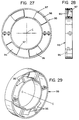
- FIG. 26 through 29 disclose a hub 95 similar in construction to that disclosed in Fig. 18-23, which hub 95 has the two half sections joined together to facilitate its attachment to a drive shaft.
- a plurality of circumferentially spaced pumping vanes 96 are suitably secured at one end to the hub 95 between an inner rim portion and an outer rim portion with the vanes lying generally within the structure of the hub such that in their normal condition the vanes are disposed in a circumferential plane that is normal to the axis of rotation of such hub 95, which axis is designated C in Fig. 27 and C-C in Fig. 29.
- Each vane has one end secured by a pin 97 to the hub 95 allowing the remaining portion of the vane 96 to deflect upon rotation of the drive shaft to which such hub is connected to and pumps water to the staves of a bearing unit with which it is associated with as described in the other embodiments.
- FIG. 30 A further modification of the invention is shown in Fig. 30 which disloses a propeller or drive shaft 100 journaled in a bearing assembly 101 similar to that described above and disclosed by Figs. 4, 7, 21 and 26, which bearing assembly has a strut barrel or housing 102 suitably supported by a strut 103.
- a cylindrically shaped rope guard 104 mounted adjacent to the strut barrel 102 is a cylindrically shaped rope guard 104 secured to shaft 100 and mounted adjacent to rope guard 104 is a cylindrically shaped hub 105 with propeller blades 106 extending radially outwardly therefrom.
- a hemi-spherically shaped dunce cap 107 Mounted on the end portion of shaft 100 and adjeacent to hub 105 is a hemi-spherically shaped dunce cap 107 with a plurality of apertures 120 therein to facilitate the exiting flow of water from the bearing asembly 101.
- a cover 110 encompasses the hub 108 and the portion of the shaft 100 adjacent thereto.
- cover 110 is suitably secured to the strut barrel 102 while the other end 112 closely encompasses the shaft 100 leaving a clearance space therebetween by which water enters into the chamber 115 defined by the outer surface of shaft 100, cover 110 and the bearing assembly 101.
- the vanes 109 pump the water from chamber 115 through the bearing assembly 101 and out through the apertures 120.
- vanes In the above described pumping action by the elastomeric or resilient vanes, such vanes by their flexibility and restricted yielding in the hub that is attached to the rotating shaft will pump water in either direction of rotation of the drive shaft.
- Such vanes are especially applicable where water flow is needed as for lubricating a bearing even though the fairwater/coupling cover condition is not present, as where only a hub and its vanes are mounted adjacent to a bearing assembly.
- Laminate 130 includes a fiber-reinforced toughened epoxy resin intermediate or core layer 131, sandwiched between elastomeric outer layers 132 and 133, respectively.
- modified or toughened epoxy resins which are additionally fiber-reinforced are preferred.
- the particular epoxy resin, modifier and reinforcement all are application-dependent.
- suitable epoxy resins and modifiers or toughening compounds therefor are well known to those of ordinary skill in the art.
- suitable fibrous reinforcements include aramids, aramid/carbon hybrids, carbon fibers, carbon/glass hybrids, ceramic fibers, glass fibers, metallic fibers, thermoplastic fibers, and the like.
- a specific example of an epoxy resin useful in the present invention is one identified by the trade name "APCO” available from Applied Plastics Co., Inc. of 612 Franklin Ave., El Segundo, CA 90245.
- This epoxy resin has a specific gravity of 1.165 and its accompanying curing agent or hardener has a specific gravity of 1.809.
- the epoxy resin has a Shore D hardness of 84 at 25°C and a glass transition temperature of 196°F.
- the viscosity of the epoxy resin is 2000 cps (1800 ⁇ 300), and the viscosity of the hardener is 410 cps (310 ⁇ 200).
- Another epoxy resin suitable for use in the present invention is "EVERFIX EPOXY RESIN” having a density of 8.5 lbs. per gallon.
- the hardener used with this epoxy resin is a modified aliphatic amine product available through Fibre Glass-Evercoat Co., Inc., 6600 Georgia Road, Cincinnati, OH 45242.
- modified epoxy resin useful in forming marine laminate 130 of the present invention could be free of fiber-reinforcement without affecting the overall concept of the present invention.
- intermediate layer 131 could be a polyester compound, again without affecting the concept of the present invention.
- elastomeric outer layer 132 it generally is an elastomeric or viscoelastic vibration-dampening material as are well known in the art and to the literature.
- An example of a suitable vibration-dampening material is DEADBEAT®, which is available from The BFGoodrich Company of Akron, Ohio. It should be noted, however, that selection of a specific vibration-dampening material is dependent on the marine application for laminate 130.
- Elastomeric outer layer 133 is an elastomer composition having slow-release biocidal properties as are well known to those of ordinary skill in the art.
- One suitable elastomeric biocidal composition useful in forming marine laminate 130 of the present invention is NOFOUL®, which also is available from The BFGoodrich Company of Akron, Ohio.
- NOFOUL® which also is available from The BFGoodrich Company of Akron, Ohio.
- a more complete description of a biocidal elastomeric composition is set forth in U.S. Patent No. 3,639,583.
- the biocidal elastomeric compositions are special rubbery compositions in which both the concentration of biocidal toxicant dissolved therein, on the one hand, and the proportion of certain types of compounding ingredients and the state of cure or vulcanization on the other, are balanced or adjusted, as to provide, when vulcanized, a rubbery elastic matrix in which the organic toxicant remains appreciably soluble and sufficiently mobile as to diffuse to the surface of the composition at a rate at which it is removed from the surface and which is finite, low and selected for the intended biocidal application.
- Such surface toxicant is released to the environment, particularly in water, by molecular release.
- biocidal rubbers Molecular release at low levels by means of these biocidal rubbers permit the use of many organic toxicants of known high biocidal activity, but which are known to hydrolyze or oxidize or which are easily absorbed or destroyed too rapidly to be useful for direct application.
- the rubber matrix holds such materials in solution and protects such toxicants until after release and, even through the biocidal activity of released material quickly dissipates, such is quickly renewed and sustained over long periods.
- High structure (reinforcing) carbon blacks, petroleum waxes, and many of the other filler and lubricant type of ingredients normally added in the compounding of rubber have the effect of reducing the rate of diffusion of organic toxicants dissolved in the vulcanized matrix.
- the biocidal rubbers contain lower levels of total compounding ingredients than those commonly employed in the same base elastomer intended for high stress, non-biocidal applications of the rubber. For example, whereas 40 to 100 parts/wt. or more of a high structure carbon black per 100 parts/wt.
- neoprene rubber requires less carbon black for diffusion control than most other rubbers. Carbon black levels of from about 5 to about 35 phr. (more preferred from about 10 to about 35 phr.) seem to produce a very wide range of release rate with neoprene.
- biocidal elastomeric compositions will have a specific gravity at 25°C greater than about 1.0.
- the effect of density of the rubber is of little moment.
- these biocidal compositions will sink and this is an advantage in destroying snails (which move throughout a body of water) and other scavenger or bottom-favoring pests or larvae and in all larvicidal applications carried out in moving waters since the toxicant is and must be released throughout the body of water to be effective in such applications.
- a phenolic (i.e., phenol/formaldehyde) resin may be employed in the form of "micro-balloons" or "micro-spheres" to absorb and hold the excess toxicant. From about 20%/wt. to about 100%/wt. of the phenolic resin based on the weight of toxicant can be employed in this manner without undue loss of vulcanizate physical properties and while otherwise controlling the toxicant release rate. Even though bis(tributyl tin) oxide is soluble in neoprene rubber to the extent of only about 9 to 10%/wt. based on the raw rubber, the use of these amounts of microspheres makes it possible to employ up to 15 phr. or more of TBTO in neoprene with very little other changes in the recipe and with an effective biocidal life measured in years.
- petroleum waxes of the type normally employed in rubber compounding for lubricity and antioxidant activity have a relatively strong suppressing effect on toxicant diffusion or toxicant release rate.
- the use of from about 1.5 to about 5 phr. of such wax, in any given composition, will contribute very materially increased biocidal life to the composition.
- filler and/or lubricant-type compounding ingredients are of lesser effect than carbon black and wax but nevertheless reduce toxicant release at higher loadings and must be taken into account when designing a formulation.
- total loadings, other than carbon black and wax, should be below about 20 phr.
- Certain ingredients of sulfur vulcanization systems notably the C10 to C18 fatty acids normally added as vulcanization accelerators and dispersants or normally present in the elastomer, apparently either react or cooperate in some manner with the organotin toxicants during vulcanization so that the biocidal activity and efficiency of the composition is relatively greater than can be attributed to the amount of original toxicant added.
- the organotin toxicants notably the C10 to C18 fatty acids normally added as vulcanization accelerators and dispersants or normally present in the elastomer, apparently either react or cooperate in some manner with the organotin toxicants during vulcanization so that the biocidal activity and efficiency of the composition is relatively greater than can be attributed to the amount of original toxicant added.
- the fatty acid materials lauric acid, palmitic acid, and oleic acid are very effective, with palmitic acid having greatest apparent activity.
- Laboratory bench scale tests have confirmed that bis(tributyltin) oxide reacts with these fatty acids. From about
- the biocidal compositions useful in this invention may employ any of the known vulcanization systems including all of the sulfur vulcanization types, metal oxide cures, peroxide cures, amine cures, etc. It is preferred, to employ sulfur vulcanization systems because these are inexpensive, they are simple and well understood, and appear to offer the most desirable biocidal vulcanizates.
- organic toxicant is meant a toxicant compound carrying in its chemical structure sufficient of chemically-bound organic groups as to render the toxicant soluble to the extent of from about 0.01% to about 20%/wt. in the "organic vulcanizable elastomer", as the latter is defined below. More preferred toxicants have, in addition, low volatility in air and low solubility in natural waters. The toxicant should have a boiling point in excess of about 150°C and most preferably in excess of about 200°C.
- the preferred toxicants should have a solubility in natural waters (i.e., water containing some "hardness") below about 50 p.p.m., more preferably below about 30 p.p.m., and most preferably not more than about 2 to 10 p.p.m.
- water containing some "hardness” i.e., water containing some "hardness"
- the exact nature of the toxicant having these properties is not too important since the choice will be dictated primarily by the target pest to be killed, controlled or repelled.
- organotin compounds of the formula R3SnX see definition below
- nitrosalicylanilide compounds and their salts the organophosphorus, and the chlorinated hydrocarbons.
- n is a number from 1 to 3 (intermediate numbers indicate mixtures), R is an alkyl or aryl group and X is a substituent radical selected from the class consisting of sulfide, oxide, halogen such as chloride, bromide, and fluoride, chromate, sulfate, nitrate, hydroxide, acetate, fatty acid groups such as acetate, octanoate, laurate, neodecanoate, rosinate (or resinate), dimethyl dithiocarbamate, naphthenate, paravinyl benzoate, acrylate, methacrylate, iso-octylmercaptoacetate, hydride or methoxide.
- Preferred R groups are alkyl groups containing from 3 to 8 carbon atoms. The butyl group seems to maximize toxicity of the tin compounds.
- Preferred X groups are oxide, sulfide or a halogen. A particularly effective member of the latter preferred class is bis(tri-n-butyl tin) oxide (“TBTO”). Other highly effective compound is bis()tri-n-butyl tin) sulfide (“TBTS”) and tributyl tin fluoride (“TBTF”).
- Typical examples of other organotin compounds useful in the biocidal rubber compositions are bis(tri-n-propyl tin) oxide, tri-n-propyl tin chloride ("TPTC"), triisopropyl tin chloride, bis(triamyl tin) oxide, triisobutyl tin chloride, tributyl tin acetate, tributyl tin chloride, triphenyl tin chloride, tributyl tin laurate, tributyl tin adipate ("TBTAd”), tributyl tin chromate bis(tributyl tin) maleate, tributyl tin neodecanoate, bis(tri-n-butyl tin) phthalate, amyl diethyl tin chloride, butyl dipropyl tin chloride, bis(tri-n-butyl tin) sulfate,
- Another highly preferred class of toxicants for use in the biocidal rubber compositions are the salicylanilides and their derivatives including their alkali-metal and alkanol amine salts such as are described in U.S. Pats. 3,079,297, 3,113,067 and 3,238,098.
- One particular toxicant of this class known commercially as "Bayluscide” (TM Bayer) has been found particularly effective in the biocidal rubbers of this invention.
- the latter material is said to be the 2-aminoethanol salt of 5,2'-dichloro-4'-nitrosalicylanilide and has achieved at least provisionally acceptance by public health authorities in some countries.
- the salicylanilide type toxicants most useful in the biocidal rubbers of this invention have the formula wherein R is hydrogen or a lower alkanoyl radical having 1 to 4 carbon atoms, R1 is hydrogen or methyl, R2 is a halogen such as chlorine, bromine or fluorine, R3 and R4 are hydrogen, methyl, or a halogen, or a nitro group, R4 , R5 and R6 are hydrogen, halogen or a nitro group and wherein always the compound contains only one nitro group and at most three halogen substituents.
- Illustrative toxicants having the above formula are 5,2'-dichloro-4',5-chloro-4'-nitrosalicylanilide, 5-nitro-4'-chlorosalicylanilide, 5,3',5'-trichloro-2'-nitrosalicylanilide, 5,2',5'-trichloro-3-methyl-4'-nitrosalicylanilide, 5,3'-dichloro-4'-nitrosalicylanilide, 5,4',6'-trichloro-2'-nitrosalicylanilide, 5'-dichloro-4'-nitrosalicylanilide, 5-bromo-2', 5,2',5'-trichloro-4-nitro-2-acetoxybenzanilide, 5,2'-dichloro-5'-trifluoro-methylsalicylanilide, and the alkali-metal and alkanolamine salts of the above and still other compounds of the above formula.
- Organo-phosphorous compounds which may be employed are "Malathion” (O,O-dimethyl phosphorothioate or diethyl mercapto-succinate) (American Cyanamid Co.), "Dasanit” (Chemagro Corporation, Kansas City, Mo., a sulfinyl phosphorothioate (C2H5O)2PSOC6H4SOCH3); and others as set forth in U.S. patent 3,639,583.
- the biocidal rubber compositions may contain anywhere between about 0.02 to about 20 parts/wt. of toxicant per 100 parts/wt. of base elastomer in the composition(hereinafter "phr.”). Where the upper limit exceeds the intrinsic solubility of the toxicant in the base elastomer, slightly increased proportions of carbon black, wax and/or other fillers and special additives (phenolic resin micro-spheres) can be employed to absorb and hold the excess toxicant. More practical concentrations are between about 0.2 to about 15 phr. of toxicant and for longest-lived biocidal effects between about 4 and about 12 phr. The concentration chosen will depend on the biocidal application and the biocidal longevity required.
- the concentration will usually be in the range of from about 1 to about 15 phr., with from about 4 to about 12 phr. being preferred.
- concentration will cover almost the entire range depending on the application, although a generally effective range is from about 2 to about 12 phr.
- Toxicant concentration can also be expressed in terms of the toxicant concentration released to the environment.
- Bayluscide is said to exhibit a solubility in distilled water of 230 p.p.m. ⁇ 50 (by weight) and less than this in hard waters.
- the organotin compounds usually exhibit a solubility below 50 p.p.m. in natural waters.
- biocidally lethal concentrations usually are well below the water solubility level.
- vulcanizable organic elastomer means any vulcanizable elastomer or rubbery material whose structural backbone consists of carbon-to-carbon chains, although such structure may contain non-hydrocarbon substituents (i.e., halogen and nitrile groups) or pendant groups (as contrasted with a silicone rubber having a backbone of O-Si-O repeating units); and which is vulcanizable or curable from the thermoplastic to the elastic condition.
- vulcanizable to an elastomeric condition is meant an ability of the rubber to be converted from a thermoplastic to an essentially elastic condition by any of the many mechanisms including, but not limited to, sulfur-vulcanization, metal-oxide curing systems, peroxide curing systems, amine curing systems, curing through metal-carboxylate linkages, and many others.
- neoprene polychloroprene
- butyl isobutylene/isoprene copolymer
- SBR sapene/butadiene rubbers
- polybutadiene rubbers such as cis-polybutadiene rubber
- synthetic polyisoprene rubbers such as cis-polyisoprene or synthetic natural rubber
- nitrile rubbers butadiene/acrylonitrile copolymers
- EPDM rubbers ethylene/propylene/dicyclopentadiene and other ethylene/propylene/diene terpolymers
- the solubility of these toxicants in all of the rubbers is between about 7% to about 15%/wt. With the nitrile rubbers toxicant solubility is adequate in the range of from about 15% to about 40%/wt. of combined acrylonitrile and rapidly decreases when the "bound" or combined acrylonitrile content of the copolymer exceeds the region of about 40%/wt.
- compositions intended for antifouling applications in seawater are neoprene, natural rubber, butyl and the nitrile rubbers containing not more than about 35%/wt., of combined acrylonitrile. Most preferred in compositions for use in antifouling applications is neoprene.
- neoprene In biocidal rubber compositions, particularly for use in larvacidal applications in fresh water, preferred rubbers are neoprene, natural rubber, butyl rubber, SBR, and EPDM rubbers. Again, most preferred for this type of application is neoprene.
- compositions of these compositions may be prepared in conventional rubber mixing and processing equipment.
- the compositions should also include antioxidants, lubricants, accelerators and curatives, and other ingredients used for quality rubber vulcanizates in accordance with the rubber compounder's art.
- the elastomer is mixed in the usual fashion with the toxicant being added to the mixing batch at the time for addition of similar non-toxic rubber compounding ingredients.
- the organotin compounds are supplied in the form of dry high melting powders which may be added at the same time as other dry and powdery compounding ingredients.
- Toxicants which are liquid or oily in consistency are added in the same fashion and at the same point in the mixing operation as are the ordinary lubricating and extender oils.
- Mixing may be carried out on two-roll rubber mills or in Banbury or other internal-type mixers. Once mixed, the composition may be sheeted off on a rubber mill or on a rubber calendar for use as sheets of antifouling rubber, or processed through an extruder as strips or tapes, or the output of the extruder fed to a pelletizer where it is cut, chopped or formed into pellets, or the stock formed into crude sheets and/or preforms for use in molding into the shapes and forms desired. The so-shaped rubber can then be vulcanized in an air or steam oven before use. The unvulcanized composition may be calendared or skim coated on fabric or other substrates to produce biocidal sheeting and fabrics for various protective uses.
- compositions for antifoulant use will be prepared as calendared sheets of uniform gauge or as formable putties which are then adhered by means of appropriate rubber-to-metal or other adhesives or, vulcanized directly to a variety of substrates such as metal plates, or as in the instant application to the intermediate layer 131 by a suitable cement or adhesive.
- the biocidal elastomeric layer of approximately 0.05 inch in the composite structure maintains its surface free of barnacles, bryozoans, hydroids, algae, bugula, mussels and other fouling genera for over 7 years.
- TBTO bis(tri-n-butyl) oxide
- Neoprene WRT polychloroprene
- the compounding recipe is as follows: Material: Parts/wt. Neoprene WRT 100.0 FEF carbon black 14.5 PBNA1 2.0 ZnO 5.0 Lauric acid 3.0 MgO 4.0 Ethylene thiourea (“Na22”) 0.75 Benzothiozyldisulfide (MBTS) 1.0 1 Phenyl beta-naphthylamine.
- MBTS Benzothiozyldisulfide
- the above materials are mixed on a cold rubber mill by first milling the rubber until a sheet forms and then adding the other materials gradually while continuing the milling.
- To the above standard formulation are added varying amounts of TBTO added as an oily liquid. The latter disappears rapidly and is absorbed by the rubber qualities.
- the resulting compositions are vulcanized for 30 or 45 minutes at 300°F in a sheet mold.
- the rubber sheets are cured 45 minutes at 300°F.
- Laminate 130 typically will be used in marine applications wherein elastomeric outer layer 133 having biocidal properties will be directly exposed to the marine environment, and more particularly seawater, while elastomer outer layer 132 has vibration-dampening properties. It is understood that although laminate 130 preferably is comprised of a fiber-reinforced toughened epoxy resin intermediate layer sandwiched between an elastomeric biocidal composition layer and an elastomeric vibration-dampening material layer, other variations of this basic structure are possible. More particularly as shown in Fig.
- laminate 135 could be comprised of a fiber-reinforced toughened epoxy resin intermediate or core layer 136 sandwiched between a pair of biocidal elastomeric composition layers 133, which would still provide laminate 135 with vibration-dampening properties due to the elastomeric base of the outer layers.
- a polyester layer could be substituted for the fiber-reinforced toughened epoxy resin intermediate layer.
- the laminate 130 and 135 of the present invention as discussed above is formed in the following manner.
- the selected fiber-reinforced and toughened epoxy resin intermediate layer preferably is in the form of a plied prepreg, that is, the fibrous reinforcement is preimpregnated with the modified epoxy resin.
- the number of plies of the prepreg is dependent on the specific marine end use.
- the prepreg then is coated on both sides by any suitable means with a primer which improves the compatibility between the epoxy resin intermediate layer 131 and elastomeric layers 132 and 133.
- primers or tiecoats for improving the compatibility between generally dissimilar materials are well known to those of ordinary skill in the art, with a preferred primer being CHEMLOK®, which is available from the Lord Corporation of Erie, PA.
- the ingredients of CHEMLOK® are as follows: containing 50% by weight of Xylene (commonly known as Xylol), 25% by weight of trichloro ethylene (commonly referred to as TCE), 5% carbon black, and 1% carbon tetrachloride.
- Xylene commonly known as Xylol
- TCE trichloro ethylene
- carbon black commonly referred to as carbon black
- carbon black 1% carbon tetrachloride
- the composite then is co-cured in an autoclave at a temperature of from about 250°F to about 350°F, desirably from about 280°F to about 310°F, and preferably at about 300°F, and at a pressure of from about 50 psi to about 140 psi, desirably from about 75 psi to about 120 psi, and preferably at about 100 psi.
- the above-described process causes a mechanical bond to form between intermediate epoxy resin layer 131 and each of elastomeric outer layers 132 , 133.
- the primer compound promotes possible chemical cross-linking between intermediate epoxy resin layer 131 and each of the elastomeric layers 132 and 133.
- each of the layers of marine laminate 130 or 135 depends on the application in which the composite is being utilized, and can be varied without affecting the concept of the present invention.
- the laminate 140 of the invention shown in Fig. 33 comprises a fiber-reinforced toughened epoxy resin intermediate layer 141 sandwiched between a pair of elastomeric outer layers 142 of viscoelastic vibration-dampening materials such as DEADBEAT® described above.
- the laminate 145 comprises a fiber-reinforced toughened epoxy resin intermediate layer 146 sandwiched between two elastomeric layers 147 of viscoelastic vibration-dampening materials such as DEADBEAT® described above.
- An elastomeric outer layer 148 having biocidal properties is suitably adhered to one of the layers 147 to provide a laminate that exhibits the properties of ensuring greater vibration dampening means while assuring the prevention of a build-up of marine life.
- the laminate 150 comprises a fiber-reinforced toughened epoxy resin intermediate layer 151 sandwiched between two elastomeric layers 152 of viscoelastic vibration-dampening materials such as DEADBEAT" described above.
- a pair of elastomeric outer layers 153 having biocidal properties as described above are suitably adhered to the outer surfaces of the layers 152 to provide a laminate that exhibits maximum vibration dampening properties while also containing maximum anti-fouling properties.
- the respective laminates 135, 140, 145, and 150 are prepared as described above with respect to laminate 130.
- the fiber-reinforced epoxy resin layers may be non-fiber-reinforced.
Landscapes
- Engineering & Computer Science (AREA)
- Mechanical Engineering (AREA)
- General Engineering & Computer Science (AREA)
- Chemical & Material Sciences (AREA)
- Combustion & Propulsion (AREA)
- Ocean & Marine Engineering (AREA)
- Sliding-Contact Bearings (AREA)
- Compositions Of Macromolecular Compounds (AREA)
- Vibration Prevention Devices (AREA)
- Physical Water Treatments (AREA)
- Support Of The Bearing (AREA)
Priority Applications (1)
| Application Number | Priority Date | Filing Date | Title |
|---|---|---|---|
| EP95119815A EP0710544A3 (de) | 1991-08-01 | 1992-07-29 | Schichtstoff und Verfahren zu seiner Herstellung |
Applications Claiming Priority (2)
| Application Number | Priority Date | Filing Date | Title |
|---|---|---|---|
| US73900391A | 1991-08-01 | 1991-08-01 | |
| US739003 | 1991-08-01 |
Related Child Applications (1)
| Application Number | Title | Priority Date | Filing Date |
|---|---|---|---|
| EP95119815.9 Division-Into | 1992-07-29 |
Publications (3)
| Publication Number | Publication Date |
|---|---|
| EP0528219A2 true EP0528219A2 (de) | 1993-02-24 |
| EP0528219A3 EP0528219A3 (en) | 1993-05-12 |
| EP0528219B1 EP0528219B1 (de) | 1996-09-25 |
Family
ID=24970402
Family Applications (2)
| Application Number | Title | Priority Date | Filing Date |
|---|---|---|---|
| EP95119815A Withdrawn EP0710544A3 (de) | 1991-08-01 | 1992-07-29 | Schichtstoff und Verfahren zu seiner Herstellung |
| EP92112909A Expired - Lifetime EP0528219B1 (de) | 1991-08-01 | 1992-07-29 | Kompositstrukturen und Wasserleitstrukturen für Schiffe |
Family Applications Before (1)
| Application Number | Title | Priority Date | Filing Date |
|---|---|---|---|
| EP95119815A Withdrawn EP0710544A3 (de) | 1991-08-01 | 1992-07-29 | Schichtstoff und Verfahren zu seiner Herstellung |
Country Status (7)
| Country | Link |
|---|---|
| US (4) | US5292270A (de) |
| EP (2) | EP0710544A3 (de) |
| KR (1) | KR930004149A (de) |
| AU (1) | AU1634992A (de) |
| BR (1) | BR9202952A (de) |
| DE (1) | DE69214065T2 (de) |
| ES (1) | ES2094856T3 (de) |
Families Citing this family (41)
| Publication number | Priority date | Publication date | Assignee | Title |
|---|---|---|---|---|
| FR2497050A1 (fr) * | 1980-12-23 | 1982-06-25 | Saphymo Stel | Dispositif de fusion par induction directe en cage froide avec confinement electromagnetique de la charge fondue |
| AU1634992A (en) * | 1991-08-01 | 1993-02-04 | B.F. Goodrich Company, The | Composite and fairwater structures for marine vessels |
| DE4418590C2 (de) * | 1994-05-27 | 1996-11-21 | Clouth Gummiwerke Ag | Verbundschichtkörper, insbesondere Fördergurt |
| DE19714420A1 (de) | 1997-04-08 | 1998-10-29 | Hackforth Gmbh & Co Kg | Wellenkupplung |
| EP1107906B1 (de) * | 1998-09-04 | 2003-08-27 | Manfred Meincke | Vorrichtung zum antrieb eines bootes |
| CA2367305A1 (en) * | 1999-03-24 | 2000-09-28 | Environmental Separation Technologies Pty Ltd. | A separator |
| US6626638B2 (en) | 1999-07-29 | 2003-09-30 | Jonathan B. Rosefsky | Ribbon drive power generation for variable flow conditions |
| US7018170B2 (en) * | 1999-07-29 | 2006-03-28 | Rosefsky Jonathan B | Ribbon drive pumping apparatus and method with added fluid |
| US6527520B2 (en) | 1999-07-29 | 2003-03-04 | Jonathan B. Rosefsky | Ribbon drive pumping with centrifugal contaminant removal |
| EP1203160B1 (de) | 1999-07-29 | 2004-06-30 | Jonathan B. Rosefsky | Bandantriebverfahren und -system |
| WO2001092103A1 (en) * | 2000-05-29 | 2001-12-06 | Environmental Separation Technologies Pty Ltd. | A centrifugal pump for a shaft bearing |
| US6325687B1 (en) * | 2000-08-14 | 2001-12-04 | David Ungerbuehler | Overheat indicator for strut bearing and stern tube bearing |
| US7325652B2 (en) * | 2001-11-06 | 2008-02-05 | Ocv Intellectual Capital, Llc | Bumper/muffler assembly |
| US20030103251A1 (en) * | 2001-12-04 | 2003-06-05 | Sanger Blossom A. | Artwork creation process using copier |
| US7172800B2 (en) * | 2003-11-03 | 2007-02-06 | Material Sciences Corporation | Sheet molding compound damper component, and methods for making and using the same |
| US7199970B2 (en) * | 2003-11-03 | 2007-04-03 | Material Sciences Corporation | Damped disc drive assembly, and method for damping disc drive assembly |
| US7387553B1 (en) | 2004-02-17 | 2008-06-17 | Brunswick Corporation | Marine drive unit overmolded with a polymer material |
| DE102005023320A1 (de) * | 2005-05-17 | 2006-11-30 | Gummiwerk Kraiburg Gmbh & Co. Kg | Verbundbauteil aus wärmehärtenden Harzen und Elastomeren, Verfahren zur Herstellung und Verwendung eines solchen Verbundteils |
| US7216922B2 (en) * | 2005-06-29 | 2007-05-15 | The Boeing Company | Fairing panel retainer apparatus |
| WO2007029317A1 (ja) * | 2005-09-07 | 2007-03-15 | Miyasaka Gomu Kabushiki Kaisha | 振動吸収体用組成物 |
| US7942237B2 (en) * | 2006-04-12 | 2011-05-17 | Ocv Intellectual Capital, Llc | Long fiber thermoplastic composite muffler system with integrated reflective chamber |
| US7934580B2 (en) * | 2006-04-12 | 2011-05-03 | Ocv Intellectual Capital, Llc | Long fiber thermoplastic composite muffler system |
| US7528195B2 (en) | 2006-12-11 | 2009-05-05 | The United States Of America As Represented By The Secretary Of The Navy | Mixing and curing carboxy-terminated butadiene-nitrile rubber, epoxy resin and curing agent |
| US7837524B2 (en) * | 2007-08-22 | 2010-11-23 | Tesvich John A | Underwater propulsion apparatus performance enhancement device and associated methods |
| GB0720387D0 (en) | 2007-10-18 | 2007-11-28 | Airbus Uk Ltd | Panel with impact protection membrane |
| DE102007052427A1 (de) | 2007-11-02 | 2009-05-07 | Schaeffler Kg | Lageranordnung für ein Lager |
| US20100307863A1 (en) * | 2007-12-14 | 2010-12-09 | Ocv Intellectual Capital, Llc | Composite muffler system thermosetable polymers |
| CN102307720A (zh) * | 2008-12-15 | 2012-01-04 | 3M创新有限公司 | 包含具有阻挡层的粘弹性层的复合材料制品 |
| ITTO20110710A1 (it) * | 2011-08-01 | 2013-02-02 | Monte Carlo Yachts S P A Con Socio Unico | Imbarcazione da diporto con struttura portante di tipo perfezionato |
| CN103603878B (zh) * | 2013-10-21 | 2015-11-18 | 宁波纬尚汽车零部件有限公司 | 一种带喷塑层的驱动轴总成 |
| CN103708017B (zh) * | 2013-12-10 | 2016-07-06 | 珠海市海斯比船舶工程有限公司 | 复合材料船艇轴架及其制造方法、复合材料船艇 |
| US10689079B2 (en) * | 2016-05-27 | 2020-06-23 | Pennestri Products, Llc | Jet pump systems |
| US11377185B2 (en) | 2016-05-27 | 2022-07-05 | Pennestri Products, Llc | Jet pump systems |
| US10627295B2 (en) | 2017-12-19 | 2020-04-21 | David Richard Ungerbuehler | Marine vessel shaft bearing overheat monitor and alarm system |
| CN110329478A (zh) * | 2019-06-18 | 2019-10-15 | 珠海超弦智能科技有限公司 | 一种用于船舶推进器的增压导流喷口 |
| US11987334B2 (en) * | 2021-01-05 | 2024-05-21 | Epco Products Inc | Outboard motor support device |
| CN113879451B (zh) * | 2021-10-29 | 2023-10-31 | 大连理工大学 | 一种用于航行体水下航行的组合圆盘式空化结构 |
| CN114194354B (zh) * | 2021-12-10 | 2024-01-23 | 海鹰企业集团有限责任公司 | 一种具有降噪功能的仿生型导流罩设计方法 |
| WO2025014649A1 (en) * | 2023-07-12 | 2025-01-16 | Owens Corning Intellectual Capital, Llc | Algae resistant polymer-based granules for asphalt shingles |
| EP4613627A1 (de) * | 2024-03-07 | 2025-09-10 | Navantia, S.A., SME | Unterwasserelemente eines wasserfahrzeugs und verfahren zur montage der unterwasserelemente |
| EP4613628A1 (de) * | 2024-03-07 | 2025-09-10 | Navantia, S.A., SME | Fairwater und verfahren zur bereitstellung von fairwaessern |
Family Cites Families (23)
| Publication number | Priority date | Publication date | Assignee | Title |
|---|---|---|---|---|
| GB236763A (en) * | 1924-09-09 | 1925-07-16 | Stephen Leggett | An improved bearing for under-water shafts |
| US2203039A (en) * | 1939-09-21 | 1940-06-04 | Evender S Aker | Shaft bearing |
| NL134190C (de) | 1959-08-27 | |||
| US3079297A (en) | 1960-05-31 | 1963-02-26 | Bayer Ag | Method of combating gastropods |
| US3238098A (en) | 1964-01-27 | 1966-03-01 | John H Howell | Method of controlling sea lamprey |
| US3407779A (en) * | 1965-12-21 | 1968-10-29 | Satterthwaite James Glenn | Marine bearing |
| US3455613A (en) * | 1966-10-11 | 1969-07-15 | Byron Jackson Inc | Composite marine bearing |
| US3606505A (en) * | 1967-07-17 | 1971-09-20 | Satterthwaite James G | Marine bearing |
| US3639583A (en) | 1968-06-28 | 1972-02-01 | Goodrich Co B F | Biocidal elastomeric compositions |
| US3515449A (en) * | 1968-09-10 | 1970-06-02 | Us Navy | Soft rubber squeeze film bearing |
| US3894169A (en) * | 1972-02-18 | 1975-07-08 | Rockwell International Corp | Acoustical damping structure and method of preparation |
| US4205034A (en) * | 1975-06-02 | 1980-05-27 | The Gates Rubber Company | Method for making a reinforced tubular article |
| US4062422A (en) * | 1976-06-21 | 1977-12-13 | The United States Of America As Represented By The Secretary Of The Navy | Antifouling damping system for sonar domes |
| SU1050966A1 (ru) * | 1982-06-17 | 1983-10-30 | Войсковая часть 27177 | Система охлаждени подшипников гребного вала судна забортной водой |
| JPS59182836A (ja) * | 1983-04-01 | 1984-10-17 | Asahi Glass Co Ltd | 含フツ素エラストマ−組成物およびそれよりなるライニング材 |
| EP0133280A3 (de) * | 1983-08-01 | 1986-03-19 | American Cyanamid Company | Durch Wärme vernetzte laminatartige Harzmatrixkompositen mit Kompressionseigenschaften |
| US4602624A (en) * | 1984-10-11 | 1986-07-29 | Case Western Reserve University | Implantable cuff, method of manufacture, and method of installation |
| US4596471A (en) * | 1985-01-07 | 1986-06-24 | The B. F. Goodrich Company | Bearing assembly |
| US4989497A (en) * | 1985-08-30 | 1991-02-05 | The United States Of America As Represented By The Administrator Of The National Aeronautics And Space Administration | Flexible diaphragm-extreme temperature usage |
| DE3812323A1 (de) * | 1988-04-14 | 1989-10-26 | Basf Ag | Faserverbundwerkstoffe |
| US5143790A (en) * | 1989-08-09 | 1992-09-01 | Westinghouse Electric Corp. | Integrally-damped steel composite laminated structure and method of attaching same |
| US5228876A (en) * | 1991-06-07 | 1993-07-20 | Woods Woodrow E | Marine exhaust system component |
| AU1634992A (en) * | 1991-08-01 | 1993-02-04 | B.F. Goodrich Company, The | Composite and fairwater structures for marine vessels |
-
1992
- 1992-05-18 AU AU16349/92A patent/AU1634992A/en not_active Abandoned
- 1992-07-29 DE DE69214065T patent/DE69214065T2/de not_active Expired - Fee Related
- 1992-07-29 EP EP95119815A patent/EP0710544A3/de not_active Withdrawn
- 1992-07-29 ES ES92112909T patent/ES2094856T3/es not_active Expired - Lifetime
- 1992-07-29 EP EP92112909A patent/EP0528219B1/de not_active Expired - Lifetime
- 1992-07-30 BR BR929202952A patent/BR9202952A/pt not_active IP Right Cessation
- 1992-08-01 KR KR1019920013913A patent/KR930004149A/ko not_active Ceased
- 1992-12-18 US US07/995,901 patent/US5292270A/en not_active Expired - Fee Related
-
1994
- 1994-03-03 US US08/205,863 patent/US5540173A/en not_active Expired - Fee Related
-
1995
- 1995-06-05 US US08/461,477 patent/US5656376A/en not_active Expired - Fee Related
- 1995-06-05 US US08/463,153 patent/US5582528A/en not_active Expired - Fee Related
Also Published As
| Publication number | Publication date |
|---|---|
| US5292270A (en) | 1994-03-08 |
| EP0710544A2 (de) | 1996-05-08 |
| KR930004149A (ko) | 1993-03-22 |
| AU1634992A (en) | 1993-02-04 |
| DE69214065T2 (de) | 1997-04-03 |
| EP0528219B1 (de) | 1996-09-25 |
| EP0528219A3 (en) | 1993-05-12 |
| BR9202952A (pt) | 1993-03-30 |
| DE69214065D1 (de) | 1996-10-31 |
| US5540173A (en) | 1996-07-30 |
| US5656376A (en) | 1997-08-12 |
| ES2094856T3 (es) | 1997-02-01 |
| US5582528A (en) | 1996-12-10 |
| EP0710544A3 (de) | 1996-09-18 |
Similar Documents
| Publication | Publication Date | Title |
|---|---|---|
| US5540173A (en) | Composite and fairwater structures for marine vessels | |
| US4596839A (en) | Elastomer PTFE composition | |
| US3979354A (en) | Non-polluting, antifouling composition and method | |
| NO873311L (no) | Elastomer pife-blanding, artikler og deres fremstillingsmetoder. | |
| Brady | Fouling-release coatings for warships | |
| EP2692789B1 (de) | Nbr-zusammensetzung und gummi-metal-laminat | |
| EP0016195B1 (de) | Verhinderung von bewuchs auf marinestrukturen | |
| CN119081530A (zh) | 一种适用于橡胶基材表面的单组份自抛光防污涂料及其制备方法 | |
| AU2006233263B2 (en) | Safety propeller | |
| KR20020000783A (ko) | 항오염성 페인트 조성물 및 이로 도포된 물품 | |
| US6303683B1 (en) | Liquid ebonite mixtures and coatings and concretes formed therefrom | |
| CN104356921A (zh) | 一种船舶表面用粉末涂料 | |
| EP0249593B1 (de) | Elastomere polytetrafluoräthylenzusammensetzungen, -gegenstände und herstellungsverfahren | |
| KR101803439B1 (ko) | 공기부양정 소음 저감장치 | |
| US8118562B2 (en) | Sacrificial blade tip | |
| KR20240098289A (ko) | 고내구성을 갖춘 함정 마운트용 방진고무 조성물 | |
| JPH06305913A (ja) | 樹脂組成物およびこれを用いた構造物 | |
| US4966925A (en) | Antifouling organometallic polymer rubber coverings | |
| JP2981120B2 (ja) | 水中生物の付着防止用ゴム組成物およびその構造物 | |
| NO168365B (no) | Polymert flersjikts-antibegroingsbelegg med et ytre sjiktav silikongummi | |
| Graner | Marine applications | |
| KR102777468B1 (ko) | 복합 방오 기능성 코팅 기술 및 이를 적용한 해양구조물의 제조방법 | |
| DK182268B1 (en) | Antifouling paint composition | |
| CN221234046U (zh) | 一种船舶舷外机通风型保护罩 | |
| CN1392208A (zh) | 仿生无毒舰船防污涂料及其制法 |
Legal Events
| Date | Code | Title | Description |
|---|---|---|---|
| PUAI | Public reference made under article 153(3) epc to a published international application that has entered the european phase |
Free format text: ORIGINAL CODE: 0009012 |
|
| AK | Designated contracting states |
Kind code of ref document: A2 Designated state(s): DE ES FR GB IT NL |
|
| PUAL | Search report despatched |
Free format text: ORIGINAL CODE: 0009013 |
|
| AK | Designated contracting states |
Kind code of ref document: A3 Designated state(s): DE ES FR GB IT NL |
|
| 17P | Request for examination filed |
Effective date: 19931022 |
|
| 17Q | First examination report despatched |
Effective date: 19950125 |
|
| GRAH | Despatch of communication of intention to grant a patent |
Free format text: ORIGINAL CODE: EPIDOS IGRA |
|
| GRAH | Despatch of communication of intention to grant a patent |
Free format text: ORIGINAL CODE: EPIDOS IGRA |
|
| GRAA | (expected) grant |
Free format text: ORIGINAL CODE: 0009210 |
|
| AK | Designated contracting states |
Kind code of ref document: B1 Designated state(s): DE ES FR GB IT NL |
|
| DX | Miscellaneous (deleted) | ||
| REF | Corresponds to: |
Ref document number: 69214065 Country of ref document: DE Date of ref document: 19961031 |
|
| ET | Fr: translation filed | ||
| ITF | It: translation for a ep patent filed | ||
| REG | Reference to a national code |
Ref country code: ES Ref legal event code: FG2A Ref document number: 2094856 Country of ref document: ES Kind code of ref document: T3 |
|
| PLBE | No opposition filed within time limit |
Free format text: ORIGINAL CODE: 0009261 |
|
| STAA | Information on the status of an ep patent application or granted ep patent |
Free format text: STATUS: NO OPPOSITION FILED WITHIN TIME LIMIT |
|
| 26N | No opposition filed | ||
| PGFP | Annual fee paid to national office [announced via postgrant information from national office to epo] |
Ref country code: FR Payment date: 20010702 Year of fee payment: 10 |
|
| PGFP | Annual fee paid to national office [announced via postgrant information from national office to epo] |
Ref country code: GB Payment date: 20010703 Year of fee payment: 10 Ref country code: DE Payment date: 20010703 Year of fee payment: 10 |
|
| PGFP | Annual fee paid to national office [announced via postgrant information from national office to epo] |
Ref country code: NL Payment date: 20010717 Year of fee payment: 10 |
|
| PGFP | Annual fee paid to national office [announced via postgrant information from national office to epo] |
Ref country code: ES Payment date: 20010808 Year of fee payment: 10 |
|
| REG | Reference to a national code |
Ref country code: GB Ref legal event code: IF02 |
|
| PG25 | Lapsed in a contracting state [announced via postgrant information from national office to epo] |
Ref country code: GB Free format text: LAPSE BECAUSE OF NON-PAYMENT OF DUE FEES Effective date: 20020729 |
|
| PG25 | Lapsed in a contracting state [announced via postgrant information from national office to epo] |
Ref country code: ES Free format text: LAPSE BECAUSE OF NON-PAYMENT OF DUE FEES Effective date: 20020730 |
|
| PG25 | Lapsed in a contracting state [announced via postgrant information from national office to epo] |
Ref country code: NL Free format text: LAPSE BECAUSE OF NON-PAYMENT OF DUE FEES Effective date: 20030201 Ref country code: DE Free format text: LAPSE BECAUSE OF NON-PAYMENT OF DUE FEES Effective date: 20030201 |
|
| GBPC | Gb: european patent ceased through non-payment of renewal fee |
Effective date: 20020729 |
|
| PG25 | Lapsed in a contracting state [announced via postgrant information from national office to epo] |
Ref country code: FR Free format text: LAPSE BECAUSE OF NON-PAYMENT OF DUE FEES Effective date: 20030331 |
|
| NLV4 | Nl: lapsed or anulled due to non-payment of the annual fee |
Effective date: 20030201 |
|
| REG | Reference to a national code |
Ref country code: FR Ref legal event code: ST |
|
| REG | Reference to a national code |
Ref country code: ES Ref legal event code: FD2A Effective date: 20030811 |
|
| PG25 | Lapsed in a contracting state [announced via postgrant information from national office to epo] |
Ref country code: IT Free format text: LAPSE BECAUSE OF NON-PAYMENT OF DUE FEES;WARNING: LAPSES OF ITALIAN PATENTS WITH EFFECTIVE DATE BEFORE 2007 MAY HAVE OCCURRED AT ANY TIME BEFORE 2007. THE CORRECT EFFECTIVE DATE MAY BE DIFFERENT FROM THE ONE RECORDED. Effective date: 20050729 |