EP0528404A2 - Dispositif de reroduction de signaux auditifs - Google Patents
Dispositif de reroduction de signaux auditifs Download PDFInfo
- Publication number
- EP0528404A2 EP0528404A2 EP92114077A EP92114077A EP0528404A2 EP 0528404 A2 EP0528404 A2 EP 0528404A2 EP 92114077 A EP92114077 A EP 92114077A EP 92114077 A EP92114077 A EP 92114077A EP 0528404 A2 EP0528404 A2 EP 0528404A2
- Authority
- EP
- European Patent Office
- Prior art keywords
- signal level
- suppressing
- sound
- level
- reproducing device
- Prior art date
- Legal status (The legal status is an assumption and is not a legal conclusion. Google has not performed a legal analysis and makes no representation as to the accuracy of the status listed.)
- Granted
Links
Images

Classifications
-
- G—PHYSICS
- G11—INFORMATION STORAGE
- G11B—INFORMATION STORAGE BASED ON RELATIVE MOVEMENT BETWEEN RECORD CARRIER AND TRANSDUCER
- G11B20/00—Signal processing not specific to the method of recording or reproducing; Circuits therefor
- G11B20/24—Signal processing not specific to the method of recording or reproducing; Circuits therefor for reducing noise
-
- H—ELECTRICITY
- H04—ELECTRIC COMMUNICATION TECHNIQUE
- H04R—LOUDSPEAKERS, MICROPHONES, GRAMOPHONE PICK-UPS OR LIKE ACOUSTIC ELECTROMECHANICAL TRANSDUCERS; ELECTRIC HEARING AIDS; PUBLIC ADDRESS SYSTEMS
- H04R5/00—Stereophonic arrangements
- H04R5/04—Circuit arrangements, e.g. for selective connection of amplifier inputs/outputs to loudspeakers, for loudspeaker detection, or for adaptation of settings to personal preferences or hearing impairments
-
- H—ELECTRICITY
- H04—ELECTRIC COMMUNICATION TECHNIQUE
- H04R—LOUDSPEAKERS, MICROPHONES, GRAMOPHONE PICK-UPS OR LIKE ACOUSTIC ELECTROMECHANICAL TRANSDUCERS; ELECTRIC HEARING AIDS; PUBLIC ADDRESS SYSTEMS
- H04R5/00—Stereophonic arrangements
- H04R5/033—Headphones for stereophonic communication
Definitions
- This invention relates to an audio signal reproducing device and is more particularly suitable for an application to, such as a portable type tape reproducer.
- One of the methods to obviate such problems, as shown in Fig. 2, is to detect the level of sound (as shown characteristics K1 and K2) and to suppress the part where the level of sound is high (as shown characteristics K11 and K12).
- an object of this invention is to provide a reproducing device capable of preventing the decline in sound quality in advance and effectively avoiding the sound leakage from earphones.
- an audio signal reproducing device which comprises amplifiers 12, 14, 16, 18, 20, 22, 24 and 26 for amplifying the reproducing signals to be obtained from the prescribed recording medium 6; earphones 28 and 30 for reproducing the output signals of amplifiers 12, 14, 16, 18, 20, 22, 24 and 26; signal level detection circuits 32, 34, 36, 38, 40, 42, 43, 44, 46, 50, 52, 54 and 58 for detecting signal level of medium to high frequency sounds regarding input signals of earphones 28 and 30; and gain control circuits 56, 60, 62, 64 and 66 for controlling gains of amplifiers 12, 14, 16, 18, 20, 22, 24 and 26; and suppresses entire frequency range of signal level of the input signal when the sound volume of medium to high frequency sounds of the input signal is high.
- the signal level of medium to high frequency is detected and when the sound volume of medium to high frequency sounds is high depending on the detected result thereof, the deterioration in sound quality can be effectively avoided and also sound leakage from earphones can be prevented by suppressing the signal level.
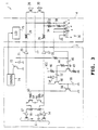
- FIG. 3 Designated generally at 1, in Fig. 3 is a tape reproducer, and the function of the tape reproducer 1 is changed by operating a controller 4 which is connected to the tape reproducer body 2.
- a magnetic tape 6 runs with the prescribed speed and the audio signal recorded on the magnetic tape 6 will be reproduced.
- reproducing signals to be obtained from the magnetic heads 8 and 10 are amplified at the head amplifiers 12 and 14 and then are supplied to the amplifiers 20 and 22 via the sound level adjusting volumes 16 and 18 and are amplified by the prescribed gains and supplied to the controller 4.
- the output signals of amplifiers 20 and 22 are supplied outputted to the stereo type earphones 28 and 30 via sub sound level adjusting volumes 24 and 26.
- music can be enjoyed with desired level of sound by adjusting the sound level adjusting volumes 16 and 18 and the level of sound can be easily adjustable by operating the sub sound level adjusting volumes 24 and 26 of the controller 4 as occasion demands.
- the input signals of the earphones 28 and 30 are added via the resistances 32 and 34, and supplied to the connecting point a of the slide switch 36.
- the slide switch 36 is adapted to change the connecting point in three steps by slide operating the operation switch, and also to connect the connecting point a and b with the resistance 38, and to connect the connecting point c and d, and to earth the connecting point e.
- the slide switch 36 maintains the signal level of the output signal at the zero level by supplying the output signal of the connecting point c to the tape reproducer body 2, on the condition that the connecting points c and e are short circuited; on the other hand, it feedbacks the input signals of the earphones 28 and 30 via the resistances 32, 34 and 38, on the condition that the connecting points b and d are short circuited.
- the slide switch 36 feedbacks the input signals of the earphones 28 and 30 to the tape reproducer body 2 via the resistances 32 and 34 on the condition that the connecting points a and c are short circuited.
- the signal level regarding the input signals of the earphones 28 and 30 can be detected directly, and then the detected level can be changed by operating the slide switch 36.
- the output signal of the slide switch 36 is supplied to the transistor 42 via the capacitor 40 and is obtained upon suppressing the low-frequency range.
- the transistor 42 is constituted by the emitter grounded circuit having the emitter resistance 43, and connects between the collector and the base with the resistance 44 and also the electric power source VCC will be supplied via the collector resistance 46.
- the transistor 50 receives the collector output of the transistor 42 upon suppressing the low-frequency range via the capacitor 52, and said corrector output will be full-wave rectified at the diode 54 connected between the base and the emitter.
- the signal level will be detected with medium to high frequency of higher than 1 [kHz].
- the transistor 56 is adapted to input the collector output of the transistor 50 to the base and also to ground the base at the capacitor 58.
- the transistor 56 is adapted to ground the emitter and also to connect the collector to the transistors 64 and 66 via the resistances 60 and 62.
- the transistors 64 and 66 are connected to the sound level adjusting volumes 16 and 18, and thus the signal level can be varied corresponding to the changes of base voltage in regards to the output signals of the sound level adjusting volumes 16 and 18.
- the earphones 28 and 30 will be actuated by the signal level determined at the sound level adjusting volumes 16 and 18 and sub sound level adjusting volumes 24 and 26.
- the input signals of the earphones 28 and 30 will be feedbacked as much level of feedbacks as determined by the resistances 34 and 38.
- the transistors 64 and 66 will be controlled depending on the level of said feedbacks thereof, and thus the sound level of the earphones 28 and 30 will be suppressed depending on the sound level of medium to high frequency of the reproducing signal.
- the earphone output is controlled to not exceed 95 [dB] in signal level.
- the input signals of the earphones 28 and 30 will be feed backed as much level of feedbacks as determined by the resistances 32 and 34, and accordingly, the sound level of the earphones 28 and 30 will be further suppressed as compared with the case of selecting the connecting points b and e.
- the earphone output is controlled to not exceed 85 [dB] in signal level.
- the level of sound suppressing function can be steadily sustained by detecting the signal level directly regarding the input signals of the earphones 28 and 30, and thus the sound leakage can be prevented.
- the occurrence of the hearing disorders can be effectively avoided as well as preventing the sound leakage.
- the level of sound can be decreased without harming the frequency characteristic of reproducing signal by controlling the transistors 64 and 66, and accordingly, the deterioration in sound quality of the tape reproducer 1 can be effectively avoided.
- the level of sounds can be decreased only when necessary by the present invention relates to a reproducing device, e.g., in the portable tape reproducer, the deterioration in sound quality is prevented in advance and the sound leakage will be effectively avoided.
- the level of sounds can be decreased only when necessary by detecting the signal level of medium to high frequency sounds and suppressing the level of sounds. And accordingly, the usability of the tape reproducer 1 can be remarkably improved.
- the slide switch 36 for the level of sound suppressing since the slide switch 36 for the level of sound suppressing is installed in the controller 4, operation can be switched easily at hand whenever necessary, and accordingly, the usability of the tape reproducer 1 can be improved.
- the output signal of the slide switch 36 is transmitted to the transistor 72 via the resistance 70 and the capacitor 71, and thus the shifting information of the slide switch 36 will be supplied to the control circuit 74 via the transistor 72.
- the control circuit 74 shift controls the overall function of the tape reproducer 1 corresponding to the operation of, such as, a reproducing operation switch (not shown in Fig. 1) and drives a liquid crystal display unit 75 which is installed in the controller 4, depending on the shifting information of the slide switch 36.
- the condition of the sound volume suppressing function can be confirmed by eye through the controller 4, and the usability of the tape reproducer 1 can be improved.
- the reproducing signals to be obtained from the magnetic heads 8 and 10 are adjusted to the prescribed level of sound at the sound level adjusting volumes 16 and 18 via the amplifiers 12 and 14 and then supplied to the earphones 28 and 30 via the amplifiers 20 and 22 and sub sound level adjusting volumes 24 and 26.
- the input signals of the earphones 28 and 30 are supplied to the transistor 42 via the resistances 32 and 34 and the slide switch 36, and after the low frequency range band is suppressed herein, full-wave rectified at the diode 54, then the signal level of medium to high frequency sounds will be detected via the transistor 50.
- the detected result of said signal level is supplied to the transistors 64 and 66 via the transistor 56 and thus the sound level of reproducing signal will be suppressed.
- the signal level of medium to high frequency sounds will be detected directly and by suppressing the signal level of said input signals depending on the detected result thereof, the level of sound can be suppressed without fail effectively avoiding the deterioration in sound quality.
- the present invention has dealt with the case of applying the present invention to the tape reproducer equipped with the controller.
- the present invention is not only limited to the above, but also suitably applied to the tape reproducer which is adapted that the volume of sound can be adjusted only by the side of the tape reproducer body.
- the embodiment discussed above has dealt with the case of only suppressing the signal level.
- the present invention is not only limited to the above, but also frequency characteristic may be corrected at the same time.
- the embodiment discussed above has dealt with the case of applying the present invention to the tape reproducers.
- the present invention is not only limited to the tape reproducers, but also widely applicable to the reproducing device which is adapted to test hearing by the earphone.
- the reproducing device which is capable of preventing the sound leakage by effectively avoiding the deterioration in sound quality, can be obtained after directly detecting the signal level of medium to high frequency sounds and by suppressing the signal level depending on the detected result.
Landscapes
- Engineering & Computer Science (AREA)
- Signal Processing (AREA)
- Physics & Mathematics (AREA)
- Acoustics & Sound (AREA)
- Signal Processing Not Specific To The Method Of Recording And Reproducing (AREA)
- Control Of Amplification And Gain Control (AREA)
- Headphones And Earphones (AREA)
- Stereophonic Arrangements (AREA)
- Recording Or Reproducing By Magnetic Means (AREA)
- Circuit For Audible Band Transducer (AREA)
- Amplifiers (AREA)
Applications Claiming Priority (2)
| Application Number | Priority Date | Filing Date | Title |
|---|---|---|---|
| JP3232403A JP3016446B2 (ja) | 1991-08-20 | 1991-08-20 | 再生装置 |
| JP232403/91 | 1991-08-20 |
Publications (3)
| Publication Number | Publication Date |
|---|---|
| EP0528404A2 true EP0528404A2 (fr) | 1993-02-24 |
| EP0528404A3 EP0528404A3 (en) | 1995-01-18 |
| EP0528404B1 EP0528404B1 (fr) | 1997-05-14 |
Family
ID=16938701
Family Applications (1)
| Application Number | Title | Priority Date | Filing Date |
|---|---|---|---|
| EP92114077A Expired - Lifetime EP0528404B1 (fr) | 1991-08-20 | 1992-08-18 | Dispositif de reproduction de signaux auditifs |
Country Status (6)
| Country | Link |
|---|---|
| US (1) | US5537668A (fr) |
| EP (1) | EP0528404B1 (fr) |
| JP (1) | JP3016446B2 (fr) |
| KR (1) | KR100240554B1 (fr) |
| DE (1) | DE69219695T2 (fr) |
| HK (1) | HK1006909A1 (fr) |
Families Citing this family (10)
| Publication number | Priority date | Publication date | Assignee | Title |
|---|---|---|---|---|
| US6488097B1 (en) | 1999-01-08 | 2002-12-03 | Pnm, Inc. | Fire protection sprinkler head support |
| JP5396685B2 (ja) | 2006-12-25 | 2014-01-22 | ソニー株式会社 | 音声出力装置、音声出力方法、音声出力システムおよび音声出力処理用プログラム |
| JP5401759B2 (ja) | 2007-01-16 | 2014-01-29 | ソニー株式会社 | 音声出力装置、音声出力方法、音声出力システムおよび音声出力処理用プログラム |
| JP4640461B2 (ja) | 2008-07-08 | 2011-03-02 | ソニー株式会社 | 音量調整装置およびプログラム |
| JP5482579B2 (ja) * | 2010-09-02 | 2014-05-07 | ソニー株式会社 | 信号処理装置および方法 |
| US8831230B2 (en) * | 2011-04-15 | 2014-09-09 | Fairchild Semiconductor Corporation | Amplifier crosstalk cancellation technique |
| US10173088B2 (en) | 2014-05-28 | 2019-01-08 | The Reliable Automatic Sprinkler Co., Inc. | Bracket for installation of a fire protection sprinkler |
| MX364612B (es) | 2014-06-27 | 2019-05-02 | Anvil Int Llc | Abrazadera ajustable y cubo para soporte de manguera flexible. |
| KR20160052405A (ko) | 2014-10-31 | 2016-05-12 | 페어차일드 세미컨덕터 코포레이션 | 오디오 크로스토크 교정 스위치 |
| US10015578B2 (en) | 2014-11-19 | 2018-07-03 | Fairchild Semiconductor Corporation | Remote ground sensing for reduced crosstalk of headset and microphone audio signals |
Family Cites Families (10)
| Publication number | Priority date | Publication date | Assignee | Title |
|---|---|---|---|---|
| US3571529A (en) * | 1968-09-09 | 1971-03-16 | Zenith Radio Corp | Hearing aid with frequency-selective agc |
| NL8001592A (nl) * | 1980-03-18 | 1981-10-16 | Philips Nv | Mfb systeem met een overnamenetwerk. |
| DE3027953A1 (de) * | 1980-07-23 | 1982-02-25 | Zuch, Erhard H., 4930 Detmold | Elektro-akustisches hoergeraet mit adaptiver filterschaltung |
| JPS59108497A (ja) * | 1982-12-14 | 1984-06-22 | Matsushita Electric Ind Co Ltd | スピ−カ保護装置 |
| EP0410157A3 (en) * | 1983-06-03 | 1992-07-08 | Mills-Ralston, Inc. | Signal processing system for use with an audio reproduction system |
| KR910007197B1 (ko) * | 1988-08-23 | 1991-09-19 | 삼성전자 주식회사 | 리모트 콘트롤회로 |
| JPH03297209A (ja) * | 1990-04-16 | 1991-12-27 | Matsushita Electric Ind Co Ltd | 音響再生装置 |
| JP2897316B2 (ja) * | 1990-02-23 | 1999-05-31 | ソニー株式会社 | 再生装置及びヘッドフォーン装置 |
| DE4017506A1 (de) * | 1990-05-31 | 1991-12-05 | Sennheiser Electronic | Schaltungsanordnung zur begrenzung der lautstaerke |
| JP3107816U (ja) | 2004-09-21 | 2005-02-17 | 株式会社三実通商 | バッグ用錠 |
-
1991
- 1991-08-20 JP JP3232403A patent/JP3016446B2/ja not_active Expired - Lifetime
-
1992
- 1992-08-18 DE DE69219695T patent/DE69219695T2/de not_active Expired - Lifetime
- 1992-08-18 EP EP92114077A patent/EP0528404B1/fr not_active Expired - Lifetime
- 1992-08-20 KR KR1019920014953A patent/KR100240554B1/ko not_active Expired - Lifetime
-
1994
- 1994-10-27 US US08/330,225 patent/US5537668A/en not_active Expired - Lifetime
-
1998
- 1998-06-22 HK HK98105924A patent/HK1006909A1/en not_active IP Right Cessation
Also Published As
| Publication number | Publication date |
|---|---|
| US5537668A (en) | 1996-07-16 |
| KR100240554B1 (ko) | 2000-01-15 |
| EP0528404B1 (fr) | 1997-05-14 |
| DE69219695T2 (de) | 1997-09-04 |
| DE69219695D1 (de) | 1997-06-19 |
| HK1006909A1 (en) | 1999-03-19 |
| JPH0549091A (ja) | 1993-02-26 |
| JP3016446B2 (ja) | 2000-03-06 |
| EP0528404A3 (en) | 1995-01-18 |
| KR930004992A (ko) | 1993-03-23 |
Similar Documents
| Publication | Publication Date | Title |
|---|---|---|
| EP0528404B1 (fr) | Dispositif de reproduction de signaux auditifs | |
| HK1006909B (en) | Audio signal reproducing device | |
| US5300892A (en) | Audio signal amplifier circuit | |
| US5323275A (en) | Digital signal recording and/or reproducing apparatus having correlated digital and analog signal level controllers | |
| US6198586B1 (en) | Voice recording/playback apparatus for producing a noise level of a voice output unit in a voice recording mode | |
| JP3243737B2 (ja) | 音量調整回路装置 | |
| JPH0993063A (ja) | オートゲインコントロール回路 | |
| JPH01151066A (ja) | テープレコーダ | |
| JPS63281271A (ja) | ノイズリダクシヨン回路 | |
| SU1543453A1 (ru) | Устройство дл снижени уровн шума при перезаписи фонограмм | |
| JP2690090B2 (ja) | テープレコーダ | |
| JP3423208B2 (ja) | 記録再生信号処理装置 | |
| KR950013446B1 (ko) | 캠코더의 오디오 기록/재생장치 | |
| JP2544441Y2 (ja) | 小型再生機器 | |
| KR910008984Y1 (ko) | 주파수별 오디오 녹음 제어장치 | |
| JP2502086Y2 (ja) | 音響再生装置 | |
| KR940004985B1 (ko) | 브이씨알의 녹음 모니터 및 서라운드 음향회로 | |
| US4148081A (en) | Volume controlled tape end alarm for tape recorder | |
| JP2715503B2 (ja) | カセットテープレコーダ | |
| US5856892A (en) | Recording apparatus with a control for selecting a gain adjustment amount | |
| JPS6112582Y2 (fr) | ||
| JP2517856Y2 (ja) | テープレコーダーのハウリング防止回路 | |
| JPH055691Y2 (fr) | ||
| JP3365019B2 (ja) | 記録装置 | |
| JP3162869B2 (ja) | 記録再生装置のノイズ低減回路 |
Legal Events
| Date | Code | Title | Description |
|---|---|---|---|
| PUAI | Public reference made under article 153(3) epc to a published international application that has entered the european phase |
Free format text: ORIGINAL CODE: 0009012 |
|
| AK | Designated contracting states |
Kind code of ref document: A2 Designated state(s): DE FR GB |
|
| PUAL | Search report despatched |
Free format text: ORIGINAL CODE: 0009013 |
|
| AK | Designated contracting states |
Kind code of ref document: A3 Designated state(s): DE FR GB |
|
| 17P | Request for examination filed |
Effective date: 19950705 |
|
| GRAG | Despatch of communication of intention to grant |
Free format text: ORIGINAL CODE: EPIDOS AGRA |
|
| 17Q | First examination report despatched |
Effective date: 19960731 |
|
| GRAH | Despatch of communication of intention to grant a patent |
Free format text: ORIGINAL CODE: EPIDOS IGRA |
|
| GRAH | Despatch of communication of intention to grant a patent |
Free format text: ORIGINAL CODE: EPIDOS IGRA |
|
| GRAA | (expected) grant |
Free format text: ORIGINAL CODE: 0009210 |
|
| AK | Designated contracting states |
Kind code of ref document: B1 Designated state(s): DE FR GB |
|
| REF | Corresponds to: |
Ref document number: 69219695 Country of ref document: DE Date of ref document: 19970619 |
|
| ET | Fr: translation filed | ||
| PLBE | No opposition filed within time limit |
Free format text: ORIGINAL CODE: 0009261 |
|
| 26N | No opposition filed | ||
| REG | Reference to a national code |
Ref country code: GB Ref legal event code: IF02 |
|
| PGFP | Annual fee paid to national office [announced via postgrant information from national office to epo] |
Ref country code: GB Payment date: 20110819 Year of fee payment: 20 Ref country code: DE Payment date: 20110823 Year of fee payment: 20 Ref country code: FR Payment date: 20110901 Year of fee payment: 20 |
|
| REG | Reference to a national code |
Ref country code: DE Ref legal event code: R071 Ref document number: 69219695 Country of ref document: DE |
|
| REG | Reference to a national code |
Ref country code: DE Ref legal event code: R071 Ref document number: 69219695 Country of ref document: DE |
|
| REG | Reference to a national code |
Ref country code: GB Ref legal event code: PE20 Expiry date: 20120817 |
|
| PG25 | Lapsed in a contracting state [announced via postgrant information from national office to epo] |
Ref country code: DE Free format text: LAPSE BECAUSE OF EXPIRATION OF PROTECTION Effective date: 20120821 Ref country code: GB Free format text: LAPSE BECAUSE OF EXPIRATION OF PROTECTION Effective date: 20120817 |