EP0528560B1 - Kombinierte Extruderkopf Anordnung zur Herstellung eines Dichtungsstreifens - Google Patents
Kombinierte Extruderkopf Anordnung zur Herstellung eines Dichtungsstreifens Download PDFInfo
- Publication number
- EP0528560B1 EP0528560B1 EP92306916A EP92306916A EP0528560B1 EP 0528560 B1 EP0528560 B1 EP 0528560B1 EP 92306916 A EP92306916 A EP 92306916A EP 92306916 A EP92306916 A EP 92306916A EP 0528560 B1 EP0528560 B1 EP 0528560B1
- Authority
- EP
- European Patent Office
- Prior art keywords
- open end
- head body
- head assembly
- shaping aperture
- extrusion head
- Prior art date
- Legal status (The legal status is an assumption and is not a legal conclusion. Google has not performed a legal analysis and makes no representation as to the accuracy of the status listed.)
- Expired - Lifetime
Links
- 238000001125 extrusion Methods 0.000 title claims description 30
- 239000000463 material Substances 0.000 claims description 73
- 229920001971 elastomer Polymers 0.000 claims description 33
- 239000005060 rubber Substances 0.000 claims description 33
- 238000007493 shaping process Methods 0.000 claims description 30
- 238000000034 method Methods 0.000 claims description 11
- 238000004519 manufacturing process Methods 0.000 claims description 10
- 235000011837 pasties Nutrition 0.000 claims description 8
- 239000012815 thermoplastic material Substances 0.000 claims description 8
- 229910052751 metal Inorganic materials 0.000 claims description 4
- 239000002184 metal Substances 0.000 claims description 4
- 238000010438 heat treatment Methods 0.000 claims description 3
- 235000012438 extruded product Nutrition 0.000 claims 1
- 229920003023 plastic Polymers 0.000 description 26
- 239000004033 plastic Substances 0.000 description 26
- 239000011521 glass Substances 0.000 description 11
- 239000011347 resin Substances 0.000 description 7
- 229920005989 resin Polymers 0.000 description 7
- 239000004743 Polypropylene Substances 0.000 description 6
- 229920001155 polypropylene Polymers 0.000 description 6
- 238000001816 cooling Methods 0.000 description 5
- 230000004048 modification Effects 0.000 description 5
- 238000012986 modification Methods 0.000 description 5
- 239000004698 Polyethylene Substances 0.000 description 4
- 229920000573 polyethylene Polymers 0.000 description 4
- -1 polypropylene Polymers 0.000 description 4
- OKTJSMMVPCPJKN-UHFFFAOYSA-N Carbon Chemical compound [C] OKTJSMMVPCPJKN-UHFFFAOYSA-N 0.000 description 3
- 238000010276 construction Methods 0.000 description 3
- 238000007796 conventional method Methods 0.000 description 3
- 238000005520 cutting process Methods 0.000 description 3
- 239000005357 flat glass Substances 0.000 description 3
- 239000003921 oil Substances 0.000 description 3
- MQIUGAXCHLFZKX-UHFFFAOYSA-N Di-n-octyl phthalate Natural products CCCCCCCCOC(=O)C1=CC=CC=C1C(=O)OCCCCCCCC MQIUGAXCHLFZKX-UHFFFAOYSA-N 0.000 description 2
- ZRALSGWEFCBTJO-UHFFFAOYSA-N Guanidine Chemical compound NC(N)=N ZRALSGWEFCBTJO-UHFFFAOYSA-N 0.000 description 2
- 239000004952 Polyamide Substances 0.000 description 2
- BJQHLKABXJIVAM-UHFFFAOYSA-N bis(2-ethylhexyl) phthalate Chemical compound CCCCC(CC)COC(=O)C1=CC=CC=C1C(=O)OCC(CC)CCCC BJQHLKABXJIVAM-UHFFFAOYSA-N 0.000 description 2
- 229910052799 carbon Inorganic materials 0.000 description 2
- 239000003795 chemical substances by application Substances 0.000 description 2
- 239000005038 ethylene vinyl acetate Substances 0.000 description 2
- 229920001200 poly(ethylene-vinyl acetate) Polymers 0.000 description 2
- 229920002647 polyamide Polymers 0.000 description 2
- 229920013716 polyethylene resin Polymers 0.000 description 2
- 229920000642 polymer Polymers 0.000 description 2
- 229920006324 polyoxymethylene Polymers 0.000 description 2
- 239000004800 polyvinyl chloride Substances 0.000 description 2
- FNSVFYNYEORBIV-UHFFFAOYSA-N 2,2-dioctylhexanedioic acid Chemical compound CCCCCCCCC(C(O)=O)(CCCC(O)=O)CCCCCCCC FNSVFYNYEORBIV-UHFFFAOYSA-N 0.000 description 1
- 229920002943 EPDM rubber Polymers 0.000 description 1
- 229920000181 Ethylene propylene rubber Polymers 0.000 description 1
- YCKRFDGAMUMZLT-UHFFFAOYSA-N Fluorine atom Chemical compound [F] YCKRFDGAMUMZLT-UHFFFAOYSA-N 0.000 description 1
- 244000043261 Hevea brasiliensis Species 0.000 description 1
- CHJJGSNFBQVOTG-UHFFFAOYSA-N N-methyl-guanidine Natural products CNC(N)=N CHJJGSNFBQVOTG-UHFFFAOYSA-N 0.000 description 1
- 229920006602 NBR/PVC Polymers 0.000 description 1
- 229930182556 Polyacetal Natural products 0.000 description 1
- XUIMIQQOPSSXEZ-UHFFFAOYSA-N Silicon Chemical compound [Si] XUIMIQQOPSSXEZ-UHFFFAOYSA-N 0.000 description 1
- FZWLAAWBMGSTSO-UHFFFAOYSA-N Thiazole Chemical compound C1=CSC=N1 FZWLAAWBMGSTSO-UHFFFAOYSA-N 0.000 description 1
- 239000002253 acid Substances 0.000 description 1
- 229920000800 acrylic rubber Polymers 0.000 description 1
- 239000000853 adhesive Substances 0.000 description 1
- 230000001070 adhesive effect Effects 0.000 description 1
- 125000003118 aryl group Chemical group 0.000 description 1
- NTXGQCSETZTARF-UHFFFAOYSA-N buta-1,3-diene;prop-2-enenitrile Chemical compound C=CC=C.C=CC#N NTXGQCSETZTARF-UHFFFAOYSA-N 0.000 description 1
- 239000000919 ceramic Substances 0.000 description 1
- 239000000498 cooling water Substances 0.000 description 1
- 238000010168 coupling process Methods 0.000 description 1
- SWSQBOPZIKWTGO-UHFFFAOYSA-N dimethylaminoamidine Natural products CN(C)C(N)=N SWSQBOPZIKWTGO-UHFFFAOYSA-N 0.000 description 1
- 239000013013 elastic material Substances 0.000 description 1
- 239000011737 fluorine Substances 0.000 description 1
- 229910052731 fluorine Inorganic materials 0.000 description 1
- NBVXSUQYWXRMNV-UHFFFAOYSA-N fluoromethane Chemical compound FC NBVXSUQYWXRMNV-UHFFFAOYSA-N 0.000 description 1
- 229910002804 graphite Inorganic materials 0.000 description 1
- 239000010439 graphite Substances 0.000 description 1
- 229920002681 hypalon Polymers 0.000 description 1
- 238000005304 joining Methods 0.000 description 1
- 238000002844 melting Methods 0.000 description 1
- 230000008018 melting Effects 0.000 description 1
- 239000003094 microcapsule Substances 0.000 description 1
- 238000002156 mixing Methods 0.000 description 1
- 239000000203 mixture Substances 0.000 description 1
- CWQXQMHSOZUFJS-UHFFFAOYSA-N molybdenum disulfide Chemical compound S=[Mo]=S CWQXQMHSOZUFJS-UHFFFAOYSA-N 0.000 description 1
- 229910052982 molybdenum disulfide Inorganic materials 0.000 description 1
- 238000000465 moulding Methods 0.000 description 1
- 229920003052 natural elastomer Polymers 0.000 description 1
- 229920001194 natural rubber Polymers 0.000 description 1
- 229920001084 poly(chloroprene) Polymers 0.000 description 1
- 229920000058 polyacrylate Polymers 0.000 description 1
- 229920005668 polycarbonate resin Polymers 0.000 description 1
- 239000004431 polycarbonate resin Substances 0.000 description 1
- 239000004810 polytetrafluoroethylene Substances 0.000 description 1
- 229920001343 polytetrafluoroethylene Polymers 0.000 description 1
- 229920000915 polyvinyl chloride Polymers 0.000 description 1
- 239000002994 raw material Substances 0.000 description 1
- 238000007789 sealing Methods 0.000 description 1
- 229910052710 silicon Inorganic materials 0.000 description 1
- 239000010703 silicon Substances 0.000 description 1
- 229920003048 styrene butadiene rubber Polymers 0.000 description 1
- 229920003051 synthetic elastomer Polymers 0.000 description 1
- 239000005061 synthetic rubber Substances 0.000 description 1
- 229920002725 thermoplastic elastomer Polymers 0.000 description 1
- 229920005992 thermoplastic resin Polymers 0.000 description 1
- 229920001187 thermosetting polymer Polymers 0.000 description 1
- KUAZQDVKQLNFPE-UHFFFAOYSA-N thiram Chemical compound CN(C)C(=S)SSC(=S)N(C)C KUAZQDVKQLNFPE-UHFFFAOYSA-N 0.000 description 1
- 229960002447 thiram Drugs 0.000 description 1
- XLYOFNOQVPJJNP-UHFFFAOYSA-N water Substances O XLYOFNOQVPJJNP-UHFFFAOYSA-N 0.000 description 1
- 238000003466 welding Methods 0.000 description 1
Images

Classifications
-
- B—PERFORMING OPERATIONS; TRANSPORTING
- B60—VEHICLES IN GENERAL
- B60J—WINDOWS, WINDSCREENS, NON-FIXED ROOFS, DOORS, OR SIMILAR DEVICES FOR VEHICLES; REMOVABLE EXTERNAL PROTECTIVE COVERINGS SPECIALLY ADAPTED FOR VEHICLES
- B60J10/00—Sealing arrangements
- B60J10/70—Sealing arrangements specially adapted for windows or windscreens
- B60J10/74—Sealing arrangements specially adapted for windows or windscreens for sliding window panes, e.g. sash guides
-
- B—PERFORMING OPERATIONS; TRANSPORTING
- B29—WORKING OF PLASTICS; WORKING OF SUBSTANCES IN A PLASTIC STATE IN GENERAL
- B29C—SHAPING OR JOINING OF PLASTICS; SHAPING OF MATERIAL IN A PLASTIC STATE, NOT OTHERWISE PROVIDED FOR; AFTER-TREATMENT OF THE SHAPED PRODUCTS, e.g. REPAIRING
- B29C48/00—Extrusion moulding, i.e. expressing the moulding material through a die or nozzle which imparts the desired form; Apparatus therefor
- B29C48/03—Extrusion moulding, i.e. expressing the moulding material through a die or nozzle which imparts the desired form; Apparatus therefor characterised by the shape of the extruded material at extrusion
- B29C48/12—Articles with an irregular circumference when viewed in cross-section, e.g. window profiles
-
- B—PERFORMING OPERATIONS; TRANSPORTING
- B29—WORKING OF PLASTICS; WORKING OF SUBSTANCES IN A PLASTIC STATE IN GENERAL
- B29C—SHAPING OR JOINING OF PLASTICS; SHAPING OF MATERIAL IN A PLASTIC STATE, NOT OTHERWISE PROVIDED FOR; AFTER-TREATMENT OF THE SHAPED PRODUCTS, e.g. REPAIRING
- B29C48/00—Extrusion moulding, i.e. expressing the moulding material through a die or nozzle which imparts the desired form; Apparatus therefor
- B29C48/15—Extrusion moulding, i.e. expressing the moulding material through a die or nozzle which imparts the desired form; Apparatus therefor incorporating preformed parts or layers, e.g. extrusion moulding around inserts
- B29C48/154—Coating solid articles, i.e. non-hollow articles
- B29C48/155—Partial coating thereof
-
- B—PERFORMING OPERATIONS; TRANSPORTING
- B29—WORKING OF PLASTICS; WORKING OF SUBSTANCES IN A PLASTIC STATE IN GENERAL
- B29C—SHAPING OR JOINING OF PLASTICS; SHAPING OF MATERIAL IN A PLASTIC STATE, NOT OTHERWISE PROVIDED FOR; AFTER-TREATMENT OF THE SHAPED PRODUCTS, e.g. REPAIRING
- B29C48/00—Extrusion moulding, i.e. expressing the moulding material through a die or nozzle which imparts the desired form; Apparatus therefor
- B29C48/16—Articles comprising two or more components, e.g. co-extruded layers
- B29C48/18—Articles comprising two or more components, e.g. co-extruded layers the components being layers
- B29C48/21—Articles comprising two or more components, e.g. co-extruded layers the components being layers the layers being joined at their surfaces
-
- B—PERFORMING OPERATIONS; TRANSPORTING
- B29—WORKING OF PLASTICS; WORKING OF SUBSTANCES IN A PLASTIC STATE IN GENERAL
- B29C—SHAPING OR JOINING OF PLASTICS; SHAPING OF MATERIAL IN A PLASTIC STATE, NOT OTHERWISE PROVIDED FOR; AFTER-TREATMENT OF THE SHAPED PRODUCTS, e.g. REPAIRING
- B29C48/00—Extrusion moulding, i.e. expressing the moulding material through a die or nozzle which imparts the desired form; Apparatus therefor
- B29C48/25—Component parts, details or accessories; Auxiliary operations
- B29C48/36—Means for plasticising or homogenising the moulding material or forcing it through the nozzle or die
- B29C48/49—Means for plasticising or homogenising the moulding material or forcing it through the nozzle or die using two or more extruders to feed one die or nozzle
-
- B—PERFORMING OPERATIONS; TRANSPORTING
- B60—VEHICLES IN GENERAL
- B60J—WINDOWS, WINDSCREENS, NON-FIXED ROOFS, DOORS, OR SIMILAR DEVICES FOR VEHICLES; REMOVABLE EXTERNAL PROTECTIVE COVERINGS SPECIALLY ADAPTED FOR VEHICLES
- B60J10/00—Sealing arrangements
-
- B—PERFORMING OPERATIONS; TRANSPORTING
- B60—VEHICLES IN GENERAL
- B60J—WINDOWS, WINDSCREENS, NON-FIXED ROOFS, DOORS, OR SIMILAR DEVICES FOR VEHICLES; REMOVABLE EXTERNAL PROTECTIVE COVERINGS SPECIALLY ADAPTED FOR VEHICLES
- B60J10/00—Sealing arrangements
- B60J10/15—Sealing arrangements characterised by the material
- B60J10/17—Sealing arrangements characterised by the material provided with a low-friction material on the surface
-
- B—PERFORMING OPERATIONS; TRANSPORTING
- B29—WORKING OF PLASTICS; WORKING OF SUBSTANCES IN A PLASTIC STATE IN GENERAL
- B29C—SHAPING OR JOINING OF PLASTICS; SHAPING OF MATERIAL IN A PLASTIC STATE, NOT OTHERWISE PROVIDED FOR; AFTER-TREATMENT OF THE SHAPED PRODUCTS, e.g. REPAIRING
- B29C48/00—Extrusion moulding, i.e. expressing the moulding material through a die or nozzle which imparts the desired form; Apparatus therefor
- B29C48/001—Combinations of extrusion moulding with other shaping operations
- B29C48/0022—Combinations of extrusion moulding with other shaping operations combined with cutting
-
- B—PERFORMING OPERATIONS; TRANSPORTING
- B29—WORKING OF PLASTICS; WORKING OF SUBSTANCES IN A PLASTIC STATE IN GENERAL
- B29K—INDEXING SCHEME ASSOCIATED WITH SUBCLASSES B29B, B29C OR B29D, RELATING TO MOULDING MATERIALS OR TO MATERIALS FOR MOULDS, REINFORCEMENTS, FILLERS OR PREFORMED PARTS, e.g. INSERTS
- B29K2009/00—Use of rubber derived from conjugated dienes, as moulding material
-
- B—PERFORMING OPERATIONS; TRANSPORTING
- B29—WORKING OF PLASTICS; WORKING OF SUBSTANCES IN A PLASTIC STATE IN GENERAL
- B29K—INDEXING SCHEME ASSOCIATED WITH SUBCLASSES B29B, B29C OR B29D, RELATING TO MOULDING MATERIALS OR TO MATERIALS FOR MOULDS, REINFORCEMENTS, FILLERS OR PREFORMED PARTS, e.g. INSERTS
- B29K2023/00—Use of polyalkenes or derivatives thereof as moulding material
- B29K2023/04—Polymers of ethylene
- B29K2023/08—Copolymers of ethylene
- B29K2023/083—EVA, i.e. ethylene vinyl acetate copolymer
Definitions
- the present invention relates in general to a weather strip which is mounted to an automotive door window frame, an automotive door opening or the like, and more particularly, the present invention relates to a combination extrusion head assembly for producing such weather strips.
- the known weather strip shown in the drawing is a glass runner 10 which is mounted to the inside wall of an automotive window frame 100.
- the glass runner 10 is generally constructed of elastic material, such as natural rubber, synthetic rubber, thermosetting resin or the like.
- the glass runner 10 comprises a base portion 1 attached to the window frame 10, side wall portions 3 and 5 raised from both sides of the base portion 1, and lip portions 3a and 5a extending inwardly downward and obliquely from respective tops of the side wall portions 3 and 5 toward the base portion 1.
- the base portion, the side wall portions 3 and 5 and the lips 3a and 5a constitute a glass runner proper 10'.
- Designated by numeral 7 is a window glass which is slidably contactable with the lip portions 3a and 5a during its opening and closing movement.
- the inside wall of the base portion 1 and the outside walls of the lip portions 3a and 5a are each equipped with a low friction layer 11 for improving the sliding ability of the window glass 7 relative to the glass runner 10. Due to provision of such friction layers 11, the wear resistance of the glass runner 10 against the window glass 7 is also increased.
- the friction layer 11 is usually constructed of thermoplastic resin, such as polyethylene resin (PE), polypropylene resin (PP) or the like.
- the glass runner proper 10' and the friction layer 11 are produced or molded by two different extrusion molding machines, and thereafter the molded parts are united through suitable coupling method, such as method of using adhesive, method of partially melting the friction layers 11, method of using a welding device, or the like.
- FR-A-2 310 207 discloses a device for producing a weather strip comprising an extrusion die having three die plates in series.
- the first die plate is fed with rubber material by a first extruder.
- Sponge rubber for forming a sealing portion is fed to the extrusion via the second die plate.
- Rubber material for forming an outer surface portion is fed to the extrusion via the third plate. Thus, only rubber materials are used.
- An object of the present invention is to provide a combination extrusion head assembly which can be used in the production of a weather strip from unvulcanized rubber material and uncured thermoplastic material as the raw materials.
- the present invention provides a combination extrusion head assembly as set forth in claim 1.
- the assembly includes a heat insulating plate having a shaping aperture through which the unvulcanized rubber material is to pass.
- the uncured but pasty thermoplastic material is introduced downstream of the heat insulating plate.
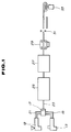
- a production line which comprises a rubber material supplier 13 from which a rubber material carrying track 15 extends to a combination extrusion head assembly 17.
- the rubber material supplier 13 is fed with an unvulcanized rubber material which includes suitable amounts of polymer(s), carbon, oil, vulcanizing agent, etc.
- polymer ethylene-propylene rubber (EPDM), styrene-butadiene rubber (SBR), polychloroprene (CR), acrylonitrile-butadiene/polyvinyl chloride copolymer (NBR/PVC), chlorosulfonated polyethylene (CSM) and acrylic rubber (ACM) are used in single or combined fashion.
- the carbon is of the grade “MAF", "FEF” or "SRF".
- the oil is of paraffinic type, naphthenic type, aromatic type, or dioctyl phthalate (DOP), or dioctyl adipic acid (DOA).
- DOP dioctyl phthalate
- DOA dioctyl adipic acid
- thiazole type, thiuram type or dithiocarheminic acid guanidine type is used as the vulcanizing agent.
- Table 1 shows the mixing ratio of components of each rubber material.
- plastic material supplier 19 is a plastic material supplier from which a plastic material carrying track 21 extends to the combination extrusion head assembly 17. That is, the plastic material supplier 19 and the above-mentioned rubber material supplier 13 are arranged in parallel with respect to the combination extrusion head assembly 17.
- the plastic material supplier 19 is fed with an uncured thermoplastic material, such as polyethylene (PE), polypropylene (PP) or the like.
- an uncured thermoplastic material such as polyethylene (PE), polypropylene (PP) or the like.
- the combination extrusion head assembly 17 extrudes a continuous shaped strap 23 which has a layered structure.
- the strap from the head assembly 17 is led into a vulcanizing oven 25 and then into a cooling tunnel 27.
- a drawing machine 29 is arranged downstream of the cooling tunnel 27.
- the strap 23 thus cooled by the cooling tunnel 27 is cut into pieces by a cutting machine 31. The cut pieces are then neatly taken up by a take-up machine 33.
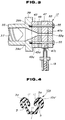
- FIGs. 2 and 3 there is shown in detail the combination extrusion head assembly 17 by which the layered and shaped strap 23 is continuously extruded.
- denoted by numeral 35 is a cylinder barrel in which an extruding screw 37 (see Fig. 3) is installed.
- the cylinder barrel 35 is communicated with the rubber material supplier 13.
- the cylinder barrel 35 has an enlarged head portion 39 in which a conical bore 39a merged with the bore of the barrel 35 is formed.
- the head portion 39 has at its outer side a circular recess 39c which is concentric with the conical bore 35a.
- the head portion 39 has at the circular recess 39c four threaded bolt holes 39b.
- the wall of the cylinder barrel 35 is formed with a steam jacket for heating the unvulcanized rubber material in the barrel 35.
- Steam inlet and outlet hoses 41 are connected to the head portion 39 to flow steam in the steam jacket.
- Designated by numeral 43 is an annular inside mouth piece which is snugly received in the circular recess 39c of the cylinder barrel 35.
- the inside mouth piece 43 is formed with a shaping aperture 43a which is shaped to correspond to the section of a product, viz., the produced weather strip 10a (see Fig. 4).
- the aperture 43a is tapered so as to be smoothly merged with the conical bore 39a of the cylinder barrel head portion 39.
- the piece 43 is further formed with four bolt holes 43b which are mated with the four threaded bolt holes 39b of the cylinder barrel head portion 39.
- a circular heat insulating plate 45 which is constructed of ceramics, fluorocarbon resin or the like.
- the insulating plate 45 has a shaping aperture 45a which is shaped to correspond to the section of the produced weather strip 10a.
- This plate 45 has also four bolt holes 45b which are mated with the four bolt holes of the mouth piece 43.
- Attached to the heat insulating plate 45 is a circular head body 47 which has a shaping aperture 47a identical to the shaping aperture 45a of the heat insulating plate 45.
- This head body 47 has also four bolt holes 47b which are mated with the four bolt holes 45b of the heat insulating plate 45.
- the circular head body 47 is formed with a passage 47c which extends from the outer surface of the head body 47 to the shaping aperture 47a of the same.
- the passage 47c is communicated with the plastic material supplier 19 to be fed with the uncured plastic material.
- the passage 47c is exposed to the shaping aperture 47a through three openings (no numerals), two being openings exposed to portions of the shaping aperture 47a, which portions correspond to positions where the inside lips 3a and 5a of the produced weather strip 10a (see Fig. 4) are located, and the remaining one being an opening exposed to a portion of the aperture 47a which portion corresponds to a position where a base portion 1 of the product 10a (see Fig. 4) is located.
- the head body 47 has an annular electric heater 49 disposed thereabout.
- the heater 49 is equipped with terminals 49a and 49b to which lead wires from an electric power source (not shown) are connected.
- the material carrying track 21 from the plastic material supplier 19 has an annular electric heater 51 disposed thereabout.
- the heater 51 is equipped with terminals 51a and 51b.
- an annular outside mouth piece 53 Attached to the circular head body 47 is an annular outside mouth piece 53 which has a shaping aperture 53a identical to the shaping aperture 47a of the circular head body 47.
- the outside mouth piece 53 also has four bolt holes 53b which are mated with the four bolt holes 47b of the head 47.
- the cylinder barrel 35, the inside mouth piece 43, the heat insulating plate 45, the head body 47 and the outside mouth piece 53 are tightly combined by four connecting bolts 55 which are received in the mated bores 53b, 47b, 45b and 43b and screwed into the threaded bolt holes 39b of the cylinder barrel head portion 39.
- the unvulcanized rubber material led into the cylinder barrel 35 from the rubber material supplier 13 is forced into the shaping aperture 43a of the inside mouth piece 43 and then into the shaping aperture 45a of the heat insulating plate 45.
- the rubber material extruded from the aperture 45a is forced to have a desired shape.
- the rubber material can keep its desired fluidity due to the heat applied thereto by the steam in the steam jacket of the cylinder barrel 35.
- the shaped rubber material from the shaping aperture 45a is then led into the shaping aperture 47a of the head body 47.
- the uncured but pasty plastic material from the plastic supplier 19 is led into the shaping aperture 47a through the above-mentioned three openings, so that three strips of the plastic material are continuously applied to three given portions of the shaped rubber material. Due to heat produced by the two heaters 49 and 51, the plastic material can keep its desired fluidity.
- the shaped rubber material thus applied with the three strips (which will be referred to as a continuous shaped strap 23 hereinafter) of the plastic material is forced into the shaping aperture 53a of the outside mouth piece 53 and then extruded from the combination extrusion head assembly 17.
- the continuous shaped strap 23 is then led into the vulcanizing oven 25 for its curing and then led into the cooling tunnel 27.
- the strap 23 thus cooled and hardened is then cut into pieces by the cutting machine 31 and neatly taken up by the take-up machine 33, as is seen from Fig. 1.
- the temperature of the extruding screw 37 should be kept at about 30°C
- the temperature of the cylinder barrel 35 should be kept at about 30°C to 60°C
- the temperature of the head portion 39 should be kept at about 40°C to 70°C
- the temperature of the inside mouth piece 43 should be kept at about 40°C to 100°C
- the temperature of the head body 47 should be kept at about 120°C to 300°C.
- the temperature of the vulcanizing oven 25 should be kept at about 150°C to 250°C. Of course, these temperatures must be changed in accordance with the types of the rubber arid plastic materials used. Thus, when occasion demands, cooling water may be fed to the steam jacket of the cylinder barrel 35 in place of the steam.
- plastic materials which are, for example, ethylene-vinyl acetate copolymer (EVA), polyamide (PA), polyacetal (POM), polycarbonate resin, polysulfonic resin, polyvinyl chloride (PVC) and TPE resin.
- EVA ethylene-vinyl acetate copolymer
- PA polyamide
- POM polyacetal
- polycarbonate resin polysulfonic resin
- PVC polyvinyl chloride
- TPE resin polyvinyl chloride
- PTFE fluorine type resin
- micro-capsules containing molybdenum disulfide, graphite, silicon oil, wax or oily material may be mixed with the plastic material. With this mixture, slidability and water repellency of the three strips (viz., the low friction layers 11) are improved.
- Fig. 4 shows the weather strip 10a produced through the above-mentioned process.
- the three low friction layers 11 formed on the given surfaces of the glass runner proper 10a' are the cured three strips of the plastic material.
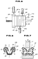
- a modification 17a of the above-mentioned combination extrusion head assembly 17 Since the modification 17a is similar in construction to the above-mentioned head assembly 17, the detailed description of the modification 17a will be directed to only parts and constructions which are different from those of the head assembly 17, and the substantially same parts are denoted by the same numerals.
- a separate annular body 39' is used, which corresponds to the head portion 39 of the above-mentioned head assembly 17.
- a cylinder barrel 35' communicated with the rubber material supplier 13 is connected through a thinner pipe 35'a to a side wall of the annular body 39'.
- the inside mouth piece 43, the heat insulating plate 45 and the head body 47 are connected to the annular body 39' in this order.
- the annular body 39' has at its front face an opening (not shown) through which an elongate metal core member 57 is continuously fed into the head assembly 17a for the reason which will become clarified therein after.
- Another head body 48 is further employed in this modification, which is attached to the head body 47 and is similar in construction to the head body 47.
- a passage 48c formed in the other head body 48 is communicated with another plastic material supplier 20.
- the passage 48c of the other head body 48 is exposed to the corresponding shaping aperture (not shown) through two openings. These two openings are exposed to portions of the corresponding shaping aperture, which portions correspond to positions where the outside lips 12 (see Fig. 6) are located.
- the outside mouth piece 53 is attached to the other head body 48.
- the annular body 39', the inside mouth piece 43, the heat insulating plate 45, the two head bodies 47 and 48, and the outside mouth piece 53 are tightly combined by the four connecting bolts 55.
- the unvulcanized rubber material from the rubber material supplier 13 is led through the cylinder barrel 35' into the annular body 39' and then forced into the shaping bore (viz., the mated shaping apertures) of the head assembly 17a.
- the metal core member 57 is inserted into the head assembly 17a, and the uncured pasty plastic materials from the plastic suppliers 19 and 20 are led into the corresponding shaping apertures through the respective openings.
- the strap 23 extruded from the head assembly 17a can have such a section as shown in Fig. 6.
- the strap 23 is thereafter led into the vulcanizing oven 25 and the cooling tunnel 27 before being cut into pieces by the cutting machine 31.
- Fig. 6 shows the weather strip 10b produced by the line in which the modified head assembly 17a is used.
- the metal core member 57 is embedded in the glass runner proper 10b'.
- the three low friction layers 11 are produced by the plastic material from the plastic supplier 19, while the other two low friction layers 12 are produced by the plastic material from the other plastic supplier 20.
- by suitably selecting the positions of the material feeding openings of the two head bodies 47 and 48 it is possible to provide a united structure of the two layers 11 and 12 on each lip portion 3a or 5a.
Landscapes
- Engineering & Computer Science (AREA)
- Mechanical Engineering (AREA)
- Extrusion Moulding Of Plastics Or The Like (AREA)
- Looms (AREA)
- Vehicle Waterproofing, Decoration, And Sanitation Devices (AREA)
- Window Of Vehicle (AREA)
- Seal Device For Vehicle (AREA)
Claims (9)
- Kombinierte Extruderkopf-Anordnung (17) zur Verwendung in einer Fertigungslinie für Dichtungsstreifen, die eine erste Material-Zufuhreinrichtung (13) zum Zuführen nicht vulkanisierten Gummimaterials und eine zweite Material-Zufuhreinrichtung (19) zum Zuführen nicht gehärteten, allerdings pastösen, thermoplastischen Materials umfaßt, wobei die Anordnung (17) aufweist:eine Zylindertrommel (35), durch die nicht vulkanisiertes Gummimaterial, das von der ersten Material-Zufuhreinrichtung (13) zugeführt wird, so zwangsgeführt wird, um zu einem stromabwärtigen, offenen Ende davon zu fließen;ein inneres Mundstück (43), das eine formende Öffnung (43a) besitzt und an dem stromabwärtigen, offenen Ende der Zylindertrommel (35) befestigt ist;eine wärmeisolierende Platte (45), die eine formende Öffnung (45a) besitzt und an dem inneren Mundstück (43) befestigt ist;einen Kopfkörper (47), der eine formende Öffnung (47a) besitzt und an der wärmeisolierenden Platte (45) befestigt ist, wobei der Kopfkörper (47) einen Material-Zufuhrkanal (47c) besitzt, wobei ein offenes Ende zu einem vorgegebenen Bereich der formenden Öffnung (47a) des Kopfkörpers (47) freigelegt ist und das andere offene Ende mit der zweiten Material-Zufuhreinrichtung (19) in Verbindung gesetzt ist, so daß nicht gehärtetes, allerdings pastöses, thermoplastisches Material, zu dem vorgegebenen Bereich durch den Material-Zufuhrkanal (47c) zugeführt wird;ein äußeres Mundstück (53), das eine formende Öffnung (53a) besitzt und an dem Kopfkörper (47) befestigt ist; undeine Einrichtung (39, 55) zum Vereinigen des inneren Mundstücks (43), der wärmeisolierenden Platte (45), des Kopfkörpers (47) und des äußeren Mundstücks (43) und zum Befestigen der vereinigten Struktur an dem stromabwärtigen, offenen Ende der Zylindertrommel (35), um so die formenden Öffnungen (43a, 45a, 47a, 53a) in Folge zu verbinden.
- Kombinierte Extruderkopf-Anordnung nach Anspruch 1, die eine Einrichtung (41) zum Beheizen des stromabwärtigen, offenen Endes der Zylindertrommel (35) umfaßt.
- Kombinierte Extruderkopf-Anordnung nach Anspruch 1 oder 2, die eine Einrichtung (49) zum Beheizen des Kopfkörpers (47) umfaßt.
- Kombinierte Extruderkopf-Anordnung nach einem der vorhergehenden Ansprüche, wobei das eine offene Ende des Material-Zufuhrkanals (47c) in mindestens zwei Bereiche unterteilt ist.
- Kombinierte Extruderkopf-Anordnung nach einem der vorhergehenden Ansprüche, die weiterhin einen zweiten Kopfkörper (48) aufweist, der eine formende Öffnung besitzt und zwischen dem ersten erwähnten Kopfkörper (47) und dem äußeren Mundstück (53) angeordnet ist, wobei der zweite Kopfkörper (48) einen Material-Zufuhrkanal (48c) besitzt, wobei ein offenes Ende zu einem vorgegebenen Bereich der formenden Öffnung des zweiten Kopfkörpers (48) hin freigelegt ist und das andere offene Ende mit einer dritten Material-Zufuhreinrichtung (20) zum Zuführen nicht gehärteten, allerdings pastösen, thermoplastischen Materials in Verbindung gesetzt ist, das zu dem vorgegebenen Bereich über den zweiten Material-Zufuhrkanal (48c) zugeführt wird.
- Kombinierte Extruderkopf-Anordnung nach Anspruch 5, wobei das eine offene Ende des zweiten Material-Zufuhrkanals (48c) in mindestens zwei Bereiche unterteilt ist.
- Kombinierte Extruderkopf-Anordnung nach einem der vorhergehenden Ansprüche, die weiterhin eine Struktur (39') aufweist, die zwischen der Zylindertrommel (35') und dem inneren Mundstück (43) angeordnet ist und die eine Öffnung besitzt, durch die ein Metallkernteil (57) für den produzierten Dichtungsstreifen (23) eingesetzt wird.
- Produktionslinie für einen Dichtungsstreifen, die eine erste Material-Zufuhreinrichtung (13) zum Zuführen nicht vulkanisierten Gummimaterials, eine zweite Material-Zufuhreinrichtung (19) zum Zuführen nicht gehärteten, allerdings pastösen, thermoplastischen Materials und eine kombinierte Extruderkopf-Anordnung (17) gemäß einem der vorhergehenden Ansprüche umfaßt.
- Verfahren zum Herstellen eines Dichtungsstreifens, das eine Produktionslinie gemäß Anspruch 8 verwendet, das aufweist:(a) Zwangsführung nicht vulkanisierten Gummimaterials von der ersten Material-Zufuhreinrichtung (13), um durch die Zylindertrommel (35) zu deren stromabwärtigen, offenen Ende zu fließen;(b) Zuführen nicht gehärteten, allerdings pastösen, thermoplastischen Materials von der zweiten Material-Zufuhreinrichtung (19) zu dem gegebenen Bereich der formenden Öffnung (47a) des Kopfkörpers (47) durch den Material-Zufuhrkanal (47c); und(c) Härten des extrudierten Produkts in einem vulkanisierenden Ofen (25).
Applications Claiming Priority (2)
| Application Number | Priority Date | Filing Date | Title |
|---|---|---|---|
| JP189727/91 | 1991-07-30 | ||
| JP3189727A JPH0531785A (ja) | 1991-07-30 | 1991-07-30 | ウエザーストリツプの製造方法 |
Publications (2)
| Publication Number | Publication Date |
|---|---|
| EP0528560A1 EP0528560A1 (de) | 1993-02-24 |
| EP0528560B1 true EP0528560B1 (de) | 1996-09-11 |
Family
ID=16246182
Family Applications (1)
| Application Number | Title | Priority Date | Filing Date |
|---|---|---|---|
| EP92306916A Expired - Lifetime EP0528560B1 (de) | 1991-07-30 | 1992-07-29 | Kombinierte Extruderkopf Anordnung zur Herstellung eines Dichtungsstreifens |
Country Status (5)
| Country | Link |
|---|---|
| US (1) | US5267846A (de) |
| EP (1) | EP0528560B1 (de) |
| JP (1) | JPH0531785A (de) |
| DE (1) | DE69213617T2 (de) |
| ES (1) | ES2094301T3 (de) |
Families Citing this family (22)
| Publication number | Priority date | Publication date | Assignee | Title |
|---|---|---|---|---|
| US5441685A (en) * | 1991-01-28 | 1995-08-15 | Tokiwa Chemical Industries Co., Ltd. | Method for producing a window glass edging member for a vehicle such as an automobile |
| US5447671A (en) * | 1991-02-24 | 1995-09-05 | Tokiwa Chemical Industries & Co., Ltd. | Window glass edging member for a vehicle such as an automobile and method for manufacturing the edging member |
| JP2539132B2 (ja) * | 1992-02-28 | 1996-10-02 | 鬼怒川ゴム工業株式会社 | ウエザストリップの製造方法 |
| JP3072941B2 (ja) * | 1992-06-26 | 2000-08-07 | 東海興業株式会社 | 自動車用モールディングの製造方法 |
| DE4314192C2 (de) * | 1993-04-30 | 1995-04-06 | Baedje K H Meteor Gummiwerke | Verfahren zur Herstellung eines Profilformteils |
| DE4314191C1 (de) * | 1993-04-30 | 1994-08-04 | Baedje K H Meteor Gummiwerke | Verfahren und Vorrichtung zur Kovulkanisation von thermoplastischen Kunststoffen und Elastomeren |
| US5345718A (en) * | 1993-05-25 | 1994-09-13 | Gencorp Inc. | Glass run guide for slidable vehicle window |
| JPH0773893B2 (ja) * | 1993-06-07 | 1995-08-09 | トキワケミカル工業株式会社 | 自動車用ウエザストリツプの成形方法 |
| US5538777A (en) * | 1993-09-01 | 1996-07-23 | Marley Mouldings Inc. | Triple extruded frame profiles |
| JP3142039B2 (ja) * | 1993-12-24 | 2001-03-07 | 東海興業株式会社 | 枠体付きガラスパネル |
| JP3572347B2 (ja) * | 1995-08-07 | 2004-09-29 | 西川ゴム工業株式会社 | ウェザーストリップの表面加工方法 |
| US6017477A (en) * | 1996-07-23 | 2000-01-25 | The Gillette Company | Extrusion apparatus and process |
| US6273983B1 (en) * | 1998-01-29 | 2001-08-14 | Tokiwa Chemical Industries Co., Ltd. | Molding for vehicle and its manufacturing method |
| US20050095374A1 (en) * | 2001-07-24 | 2005-05-05 | Liggett Cothran | Composites containing crosslinkable thermoplastic and TPV show layer |
| US6458301B1 (en) * | 2001-08-27 | 2002-10-01 | Schlegel Corporation | Method for forming weatherseals from an interchangeable insert die assembly |
| CN102476441B (zh) * | 2010-11-30 | 2015-03-25 | 比亚迪股份有限公司 | 一种汽车车窗密封条的挤出模具 |
| KR20120110634A (ko) * | 2011-03-30 | 2012-10-10 | (주)엘지하우시스 | 탄성층이 구비된 합성목재 |
| DK2948017T3 (en) * | 2013-01-25 | 2018-12-03 | Nite Ize Inc | Extruded zipper of several materials and methods |
| DE102016101312A1 (de) * | 2016-01-26 | 2017-07-27 | Cooper Standard GmbH | Profilstrang für ein Kraftfahrzeug und Profilstrang-Herstellungsverfahren |
| FR3061062A1 (fr) * | 2016-12-22 | 2018-06-29 | Compagnie Generale Des Etablissements Michelin | Installation d’extrusion comportant une tete d’extrusion perfectionnee |
| CN112356475B (zh) * | 2020-12-04 | 2022-07-15 | 德清尚邑塑料制品有限公司 | 一种滑块式密封袋密封条的生产工艺及其治具和挤出设备 |
| CN114536710B (zh) * | 2022-01-10 | 2025-05-13 | 广州东海敏孚汽车部件有限公司 | 一种滑轨饰条的加工工艺 |
Family Cites Families (19)
| Publication number | Priority date | Publication date | Assignee | Title |
|---|---|---|---|---|
| GB1545511A (en) * | 1975-05-07 | 1979-05-10 | Schlegel Uk Ltd | Extruded edge protector trim strip |
| US4187270A (en) * | 1977-07-22 | 1980-02-05 | The B. F. Goodrich Company | Extrusion apparatus |
| FR2437289A1 (fr) * | 1978-09-27 | 1980-04-25 | Ono | Dispositif d'alimentation d'une filiere de fabrication de feuilles en matiere thermoplastique |
| CH642911A5 (de) * | 1980-03-26 | 1984-05-15 | Schlegel Corp | Verfahren und vorrichtung zum aufbringen von velourbaendchen auf profile aus elastischen massen. |
| DE3405973A1 (de) * | 1984-02-18 | 1985-08-22 | Continental Gummi-Werke Ag, 3000 Hannover | Verfahren zum herstellen von dichtungsstreifen und aehnlichen profilstraengen aus kautschuk und kautschukartigen elastomeren |
| CH664528A5 (de) * | 1984-11-08 | 1988-03-15 | Daetwyler Ag | Verfahren zur herstellung einer spritzgiessvorrichtung. |
| US4963403A (en) * | 1987-10-30 | 1990-10-16 | Color Custom, Inc. | Unitary composite molding strip |
| US4817255A (en) * | 1987-11-19 | 1989-04-04 | Shaw Jr Howard C | Insertion-removal monitor/control for seal carrier manufacture |
| US4830898A (en) * | 1987-12-16 | 1989-05-16 | Sterling Engineered Products Inc. | Extruded vinyl molding incorporating a stiffener |
| US5013379A (en) * | 1988-01-25 | 1991-05-07 | Gencorp Inc. | Cohesive bonding process for forming a laminate of a wear resistant thermoplastic and a weather resistant rubber |
| FR2627835B1 (fr) * | 1988-02-26 | 1991-05-17 | Hutchinson | Coulisse d'etancheite de glace mobile, notamment de vitre de vehicule automobile |
| FR2633570B1 (fr) * | 1988-06-29 | 1991-04-12 | Hutchinson | Lecheur de bas de glace mobile de vehicule automobile |
| FR2634816B1 (fr) * | 1988-07-28 | 1990-11-02 | Hutchinson | Coulisse de guidage de glace mobile, notamment de glace ou vitre d'automobile |
| FR2636572B1 (fr) * | 1988-08-25 | 1993-11-12 | Hutchinson | Profil d'etancheite de glace mobile, notamment de glace ou vitre d'automobile |
| FR2638780B1 (fr) * | 1988-11-08 | 1991-02-15 | Mesnel Sa Ets | Profile pour le guidage et l'etancheite d'une glace mobile, notamment de porte d'automobile, et son procede de fabrication |
| US5087488A (en) * | 1989-10-19 | 1992-02-11 | Aeroquip Corporation | Method and apparatus for forming a plastic article with an overlay of varying thickness having a shaded color appearance |
| JP2931036B2 (ja) * | 1990-05-09 | 1999-08-09 | 東海興業株式会社 | シール材、並びにその成形方法及び装置 |
| JPH0459352A (ja) * | 1990-06-29 | 1992-02-26 | Toyoda Gosei Co Ltd | ゴム押出品の製造方法 |
| US5137675A (en) * | 1991-05-13 | 1992-08-11 | Gencorp Inc. | Apparatus and method for coextruding materials having different temperature dependent properties |
-
1991
- 1991-07-30 JP JP3189727A patent/JPH0531785A/ja active Pending
-
1992
- 1992-07-28 US US07/922,017 patent/US5267846A/en not_active Expired - Fee Related
- 1992-07-29 ES ES92306916T patent/ES2094301T3/es not_active Expired - Lifetime
- 1992-07-29 EP EP92306916A patent/EP0528560B1/de not_active Expired - Lifetime
- 1992-07-29 DE DE69213617T patent/DE69213617T2/de not_active Expired - Fee Related
Also Published As
| Publication number | Publication date |
|---|---|
| JPH0531785A (ja) | 1993-02-09 |
| US5267846A (en) | 1993-12-07 |
| DE69213617T2 (de) | 1997-02-27 |
| EP0528560A1 (de) | 1993-02-24 |
| ES2094301T3 (es) | 1997-01-16 |
| DE69213617D1 (de) | 1996-10-17 |
Similar Documents
| Publication | Publication Date | Title |
|---|---|---|
| EP0528560B1 (de) | Kombinierte Extruderkopf Anordnung zur Herstellung eines Dichtungsstreifens | |
| EP0325830B1 (de) | Verfahren zum Verbinden durch Kohäsion für die Herstellung eines Laminates aus einem verschleissbeständigen Thermoplast und einem wetterbeständigen Gummi | |
| US6899304B2 (en) | Method for forming a fastener | |
| EP1040950B1 (de) | Fahrzeugdichtung | |
| US5013379A (en) | Cohesive bonding process for forming a laminate of a wear resistant thermoplastic and a weather resistant rubber | |
| US5736215A (en) | Process for the manufacture of a profile part | |
| US6558146B1 (en) | Extrusion deposition molding with in-line compounding of reinforcing fibers | |
| US4676532A (en) | T-shaped rubber hose | |
| US20040043188A1 (en) | Weather strip for car and production method thereof | |
| US20040018339A1 (en) | Motor vehicle seal assembly and method of manufacture | |
| JPH0459352A (ja) | ゴム押出品の製造方法 | |
| US5334458A (en) | Rubber/plastic co-extrusion | |
| EP0719637B1 (de) | Verfahren zum Dekorieren von extrudierten Gummikörpern | |
| JPH03157238A (ja) | 車両用のモールディング兼ウエザーストリップ | |
| US6739599B1 (en) | Molding and method and device for manufacturing the molding | |
| WO2003018289A1 (en) | Method for forming weatherseals from an interchangeable insert die assembly | |
| CA1284780C (en) | Crosslinking the surface of rubber molding | |
| US20090098234A1 (en) | Screw with Carbide Inserts | |
| EP1021288A2 (de) | Vorrichtung und verfahren zum koextrudieren von materialien mit unterschiedlicher temperatur | |
| US20020031568A1 (en) | Metal mold for producing a synthetic resin molded product in a compression-molding method | |
| KR960021434A (ko) | 장섬유 강화 열가소성 수지 조성물 및 그 제조방법 | |
| JP2560394B2 (ja) | モールディングの製造方法 | |
| JP2950604B2 (ja) | ガラスラン及びその製造方法 | |
| JP2882987B2 (ja) | 多層フイルムの押出装置 | |
| JPH06198701A (ja) | 枠材にガスケットを一体化する成形方法、およびその成形物、およびその成形物を用いた板材の取付け構造 |
Legal Events
| Date | Code | Title | Description |
|---|---|---|---|
| PUAI | Public reference made under article 153(3) epc to a published international application that has entered the european phase |
Free format text: ORIGINAL CODE: 0009012 |
|
| 17P | Request for examination filed |
Effective date: 19920819 |
|
| AK | Designated contracting states |
Kind code of ref document: A1 Designated state(s): DE ES GB IT |
|
| 17Q | First examination report despatched |
Effective date: 19950217 |
|
| GRAH | Despatch of communication of intention to grant a patent |
Free format text: ORIGINAL CODE: EPIDOS IGRA |
|
| GRAH | Despatch of communication of intention to grant a patent |
Free format text: ORIGINAL CODE: EPIDOS IGRA |
|
| GRAA | (expected) grant |
Free format text: ORIGINAL CODE: 0009210 |
|
| AK | Designated contracting states |
Kind code of ref document: B1 Designated state(s): DE ES GB IT |
|
| REF | Corresponds to: |
Ref document number: 69213617 Country of ref document: DE Date of ref document: 19961017 |
|
| ITF | It: translation for a ep patent filed | ||
| REG | Reference to a national code |
Ref country code: ES Ref legal event code: FG2A Ref document number: 2094301 Country of ref document: ES Kind code of ref document: T3 |
|
| PLBE | No opposition filed within time limit |
Free format text: ORIGINAL CODE: 0009261 |
|
| STAA | Information on the status of an ep patent application or granted ep patent |
Free format text: STATUS: NO OPPOSITION FILED WITHIN TIME LIMIT |
|
| PG25 | Lapsed in a contracting state [announced via postgrant information from national office to epo] |
Ref country code: ES Free format text: LAPSE BECAUSE OF NON-PAYMENT OF DUE FEES Effective date: 19970730 |
|
| 26N | No opposition filed | ||
| PGFP | Annual fee paid to national office [announced via postgrant information from national office to epo] |
Ref country code: DE Payment date: 20000724 Year of fee payment: 9 |
|
| PGFP | Annual fee paid to national office [announced via postgrant information from national office to epo] |
Ref country code: GB Payment date: 20000726 Year of fee payment: 9 |
|
| PG25 | Lapsed in a contracting state [announced via postgrant information from national office to epo] |
Ref country code: GB Free format text: LAPSE BECAUSE OF NON-PAYMENT OF DUE FEES Effective date: 20010729 |
|
| GBPC | Gb: european patent ceased through non-payment of renewal fee |
Effective date: 20010729 |
|
| PG25 | Lapsed in a contracting state [announced via postgrant information from national office to epo] |
Ref country code: DE Free format text: LAPSE BECAUSE OF NON-PAYMENT OF DUE FEES Effective date: 20020501 |
|
| REG | Reference to a national code |
Ref country code: ES Ref legal event code: FD2A Effective date: 19980811 |
|
| PG25 | Lapsed in a contracting state [announced via postgrant information from national office to epo] |
Ref country code: IT Free format text: LAPSE BECAUSE OF NON-PAYMENT OF DUE FEES;WARNING: LAPSES OF ITALIAN PATENTS WITH EFFECTIVE DATE BEFORE 2007 MAY HAVE OCCURRED AT ANY TIME BEFORE 2007. THE CORRECT EFFECTIVE DATE MAY BE DIFFERENT FROM THE ONE RECORDED. Effective date: 20050729 |