EP0528683B1 - Procédé et dispositif pour appliquer à chaud un bandage en caoutchouc sur une carcasse de pneu - Google Patents
Procédé et dispositif pour appliquer à chaud un bandage en caoutchouc sur une carcasse de pneu Download PDFInfo
- Publication number
- EP0528683B1 EP0528683B1 EP92307568A EP92307568A EP0528683B1 EP 0528683 B1 EP0528683 B1 EP 0528683B1 EP 92307568 A EP92307568 A EP 92307568A EP 92307568 A EP92307568 A EP 92307568A EP 0528683 B1 EP0528683 B1 EP 0528683B1
- Authority
- EP
- European Patent Office
- Prior art keywords
- tyre carcass
- crown surface
- carcass
- die
- cushion gum
- Prior art date
- Legal status (The legal status is an assumption and is not a legal conclusion. Google has not performed a legal analysis and makes no representation as to the accuracy of the status listed.)
- Expired - Lifetime
Links
- 238000000034 method Methods 0.000 title claims description 30
- 238000001125 extrusion Methods 0.000 claims description 11
- 239000010410 layer Substances 0.000 claims description 6
- 239000002356 single layer Substances 0.000 claims description 2
- 230000007246 mechanism Effects 0.000 description 9
- 230000008569 process Effects 0.000 description 9
- 239000000463 material Substances 0.000 description 8
- 239000000853 adhesive Substances 0.000 description 6
- 230000001070 adhesive effect Effects 0.000 description 6
- 238000003490 calendering Methods 0.000 description 6
- 150000001875 compounds Chemical class 0.000 description 3
- 239000002699 waste material Substances 0.000 description 3
- 230000032683 aging Effects 0.000 description 2
- 239000004568 cement Substances 0.000 description 2
- 238000011109 contamination Methods 0.000 description 2
- 238000002360 preparation method Methods 0.000 description 2
- 238000000926 separation method Methods 0.000 description 2
- 230000015556 catabolic process Effects 0.000 description 1
- 230000008859 change Effects 0.000 description 1
- 238000004891 communication Methods 0.000 description 1
- 239000002131 composite material Substances 0.000 description 1
- 230000007812 deficiency Effects 0.000 description 1
- 238000006731 degradation reaction Methods 0.000 description 1
- 230000002939 deleterious effect Effects 0.000 description 1
- 238000006073 displacement reaction Methods 0.000 description 1
- 230000000694 effects Effects 0.000 description 1
- 238000005516 engineering process Methods 0.000 description 1
- 238000011065 in-situ storage Methods 0.000 description 1
- 230000003647 oxidation Effects 0.000 description 1
- 238000007254 oxidation reaction Methods 0.000 description 1
- 238000010422 painting Methods 0.000 description 1
- 239000004033 plastic Substances 0.000 description 1
- 230000001681 protective effect Effects 0.000 description 1
- 238000005507 spraying Methods 0.000 description 1
- 230000007306 turnover Effects 0.000 description 1
- 230000000007 visual effect Effects 0.000 description 1
Images



Classifications
-
- B—PERFORMING OPERATIONS; TRANSPORTING
- B29—WORKING OF PLASTICS; WORKING OF SUBSTANCES IN A PLASTIC STATE IN GENERAL
- B29D—PRODUCING PARTICULAR ARTICLES FROM PLASTICS OR FROM SUBSTANCES IN A PLASTIC STATE
- B29D30/00—Producing pneumatic or solid tyres or parts thereof
- B29D30/06—Pneumatic tyres or parts thereof (e.g. produced by casting, moulding, compression moulding, injection moulding, centrifugal casting)
- B29D30/52—Unvulcanised treads, e.g. on used tyres; Retreading
- B29D30/58—Applying bands of rubber treads, i.e. applying camel backs
- B29D30/62—Applying bands of rubber treads, i.e. applying camel backs by extrusion or injection of the tread on carcass
-
- B—PERFORMING OPERATIONS; TRANSPORTING
- B29—WORKING OF PLASTICS; WORKING OF SUBSTANCES IN A PLASTIC STATE IN GENERAL
- B29C—SHAPING OR JOINING OF PLASTICS; SHAPING OF MATERIAL IN A PLASTIC STATE, NOT OTHERWISE PROVIDED FOR; AFTER-TREATMENT OF THE SHAPED PRODUCTS, e.g. REPAIRING
- B29C48/00—Extrusion moulding, i.e. expressing the moulding material through a die or nozzle which imparts the desired form; Apparatus therefor
- B29C48/03—Extrusion moulding, i.e. expressing the moulding material through a die or nozzle which imparts the desired form; Apparatus therefor characterised by the shape of the extruded material at extrusion
- B29C48/07—Flat, e.g. panels
-
- B—PERFORMING OPERATIONS; TRANSPORTING
- B29—WORKING OF PLASTICS; WORKING OF SUBSTANCES IN A PLASTIC STATE IN GENERAL
- B29C—SHAPING OR JOINING OF PLASTICS; SHAPING OF MATERIAL IN A PLASTIC STATE, NOT OTHERWISE PROVIDED FOR; AFTER-TREATMENT OF THE SHAPED PRODUCTS, e.g. REPAIRING
- B29C48/00—Extrusion moulding, i.e. expressing the moulding material through a die or nozzle which imparts the desired form; Apparatus therefor
- B29C48/03—Extrusion moulding, i.e. expressing the moulding material through a die or nozzle which imparts the desired form; Apparatus therefor characterised by the shape of the extruded material at extrusion
- B29C48/07—Flat, e.g. panels
- B29C48/08—Flat, e.g. panels flexible, e.g. films
-
- B—PERFORMING OPERATIONS; TRANSPORTING
- B29—WORKING OF PLASTICS; WORKING OF SUBSTANCES IN A PLASTIC STATE IN GENERAL
- B29C—SHAPING OR JOINING OF PLASTICS; SHAPING OF MATERIAL IN A PLASTIC STATE, NOT OTHERWISE PROVIDED FOR; AFTER-TREATMENT OF THE SHAPED PRODUCTS, e.g. REPAIRING
- B29C48/00—Extrusion moulding, i.e. expressing the moulding material through a die or nozzle which imparts the desired form; Apparatus therefor
- B29C48/03—Extrusion moulding, i.e. expressing the moulding material through a die or nozzle which imparts the desired form; Apparatus therefor characterised by the shape of the extruded material at extrusion
- B29C48/12—Articles with an irregular circumference when viewed in cross-section, e.g. window profiles
-
- B—PERFORMING OPERATIONS; TRANSPORTING
- B29—WORKING OF PLASTICS; WORKING OF SUBSTANCES IN A PLASTIC STATE IN GENERAL
- B29C—SHAPING OR JOINING OF PLASTICS; SHAPING OF MATERIAL IN A PLASTIC STATE, NOT OTHERWISE PROVIDED FOR; AFTER-TREATMENT OF THE SHAPED PRODUCTS, e.g. REPAIRING
- B29C48/00—Extrusion moulding, i.e. expressing the moulding material through a die or nozzle which imparts the desired form; Apparatus therefor
- B29C48/25—Component parts, details or accessories; Auxiliary operations
- B29C48/30—Extrusion nozzles or dies
- B29C48/305—Extrusion nozzles or dies having a wide opening, e.g. for forming sheets
-
- B—PERFORMING OPERATIONS; TRANSPORTING
- B29—WORKING OF PLASTICS; WORKING OF SUBSTANCES IN A PLASTIC STATE IN GENERAL
- B29C—SHAPING OR JOINING OF PLASTICS; SHAPING OF MATERIAL IN A PLASTIC STATE, NOT OTHERWISE PROVIDED FOR; AFTER-TREATMENT OF THE SHAPED PRODUCTS, e.g. REPAIRING
- B29C48/00—Extrusion moulding, i.e. expressing the moulding material through a die or nozzle which imparts the desired form; Apparatus therefor
- B29C48/25—Component parts, details or accessories; Auxiliary operations
- B29C48/30—Extrusion nozzles or dies
- B29C48/35—Extrusion nozzles or dies with rollers
-
- B—PERFORMING OPERATIONS; TRANSPORTING
- B29—WORKING OF PLASTICS; WORKING OF SUBSTANCES IN A PLASTIC STATE IN GENERAL
- B29D—PRODUCING PARTICULAR ARTICLES FROM PLASTICS OR FROM SUBSTANCES IN A PLASTIC STATE
- B29D30/00—Producing pneumatic or solid tyres or parts thereof
- B29D30/06—Pneumatic tyres or parts thereof (e.g. produced by casting, moulding, compression moulding, injection moulding, centrifugal casting)
- B29D30/52—Unvulcanised treads, e.g. on used tyres; Retreading
- B29D30/54—Retreading
- B29D2030/544—Applying an intermediate adhesive layer, e.g. cement or cushioning element between carcass and tread
-
- B—PERFORMING OPERATIONS; TRANSPORTING
- B29—WORKING OF PLASTICS; WORKING OF SUBSTANCES IN A PLASTIC STATE IN GENERAL
- B29L—INDEXING SCHEME ASSOCIATED WITH SUBCLASS B29C, RELATING TO PARTICULAR ARTICLES
- B29L2030/00—Pneumatic or solid tyres or parts thereof
- B29L2030/002—Treads
-
- Y—GENERAL TAGGING OF NEW TECHNOLOGICAL DEVELOPMENTS; GENERAL TAGGING OF CROSS-SECTIONAL TECHNOLOGIES SPANNING OVER SEVERAL SECTIONS OF THE IPC; TECHNICAL SUBJECTS COVERED BY FORMER USPC CROSS-REFERENCE ART COLLECTIONS [XRACs] AND DIGESTS
- Y10—TECHNICAL SUBJECTS COVERED BY FORMER USPC
- Y10S—TECHNICAL SUBJECTS COVERED BY FORMER USPC CROSS-REFERENCE ART COLLECTIONS [XRACs] AND DIGESTS
- Y10S156/00—Adhesive bonding and miscellaneous chemical manufacture
- Y10S156/909—Apparatus for applying new tread to used tire casing, e.g. retreading, recapping
Definitions
- the present invention relates generally to tyre retreading.
- the cushion gum material was historically pre-manufactured in the form of a calendered sheet.
- the sheet is slit to various standardized widths and coiled with a plastic release film interposed between successive wraps of the sheet.
- the prepared coils of cushion gum would be maintained in inventory in a wide variety of widths until a need arises for cushion gum of that particular width.
- this procedure requires that the crown surface on the tyre carcass be buffed and then treated with an adhesive, or cement compound, prior to the application of the cold cushion gum.
- the adhesive may be applied by painting with a brush or by a roller or by spraying. Any of these processes require the expenditure of time and materials resulting in an increase in the retreading cost.
- the operator selects the proper strip of cushion gum to be applied. The operator may have to search among the available inventory to locate a strip of the correct length, width and thickness. One end of the strip is manually applied to the carcass by the operator.
- the operator then operates a spin control to cause the tyre carcass to rotate while a tensile force is being applied to the strip as it is maintained in alignment with the circumference of the carcass.
- a spin control to cause the tyre carcass to rotate while a tensile force is being applied to the strip as it is maintained in alignment with the circumference of the carcass.
- the operator will stop the rotation of the carcass, retro-rotate the carcass slightly and cut the strip to length.
- the ends of the strip are then spliced in an overlapped fashion.
- the strip of cushion is stitched to the tyre casing and the protective release film is removed. Thereafter the precured tread stock is manually applied and hand spliced (edge to edge). This splice is generally secured with staples.
- the historic method of cold-capping with pre-calendered cushion gum requires that the user manually position the leading edge of a single, wide, strip of cushion gum fully across the crown of the tyre carcass and then rotate the carcass through one revolution to wind the cushion gum about the circumference of the tyre carcass with the release film facing radially outwardly.
- the presence of the release film tends to preclude contamination of the radially outer surface of the cushion gum, which would occur without the release film if the worker were not careful.
- the release film also permits the gum to be coiled without the successive layers adhering to each other and allows external stitching.
- the entire circumferential extent of the tyre carcass was wrapped with the cushion gum sheet prior to "cutting-in” the required splice.
- the cushion gum ply would then be roller-stitched to the tyre carcass and the release film stripped off in preparation for the application of the pre-cured tread.
- Hot-capping Another historic method and apparatus available in the industry for retreading tyres is known as the "hot-capping" procedure.
- the hot-capping procedure and an exemplary apparatus for performing that method, are described in US-A-3251722 and US-A-3177918 to R. G. Holman.
- uncured tyre tread material is layered onto the crown, and perhaps a portion of each shoulder, of a tyre carcass to a sufficient radial thickness that the tyre carcass, with the tread material adhering to the circumference thereof, can be received within a mould to form the tread design and to cure the tread rubber in situ .
- FR-A-2359700 which generally discloses an apparatus for applying hot cushion gum in a layer of predetermined thickness and width to the crown surface of a tyre carcass having a sagittal plane, the apparatus comprising means for rotating the tyre carcass, extrusion means for dispensing the hot cushion gum, die means, and an internal passage within the die means for conducting the hot cushion gum from the extrusion means and forming a strip having a predetermined overall width.
- the aforementioned generally disclosed apparatus is characterized by means for selectively angularly disposing the die means relative to the sagittal plane of the tyre carcass to determine the width of the strip as it is applied to the crown surface of the tyre carcass from the die means.
- the aforesaid FR-A-2359700 also generally discloses a method of applying a strip of hot cushion gum to the crown surface of a tyre carcass, comprising the steps of mounting the tyre carcass having an outer, circumferential said crown surface of predetermined width to be covered with a single layer of the hot cushion gum, presenting an extrusion die head to the crown surface, bringing the die head into contiguous juxtaposition with the crown surface, rotating the tyre carcass at a predetermined angular velocity, and extruding the hot cushion gum through the die head on to the crown surface of the tyre carcass.
- the aforementioned generally disclosed method is characterized by the further step of selectively positioning the die head at an angle relative to the crown surface, with a means for so selectively angularly disposing the die head, to establish the desired effective width of the strip applied by the die head to the crown surface.
- the apparatus and method of the present invention are advantageous compared to those specifically disclosed in FR-A-235970 in that only a fixed die means or die head is contemplated therein with the provision of adjustable attachments for changing the configuration of the discharge orifice of the die to accommodate for different widths of the crown surface, whereas with the present invention the effective width of the gum strip appropriate to that of the crown surface is determined by angularly adjusting the die by which tyres may be retreaded having a range of carcass widths without the complexity of providing such adjustable attachments.
- the apparatus and method of the present invention also overcome the discussed deficiencies of the prior art by not only eliminating the need for extensive hand labour currently required in selecting and cutting the strip but also, because the temperature of the strip can be elevated, the cushion gum will tend to impregnate the crown surface of that tyre carcass, thereby eliminating the application of an adhesive.
- a preferred apparatus of the present invention includes an extruder and die head which are effective to present a strip of hot cushion gum having constant cross sectional dimensions to a buffed tyre carcass mounted on a rotatable device which controls the angular velocity of the tyre carcass.
- the angular velocity of the tyre carcass will affect, and control, the thickness of the hot cushion gum strip applied to the carcass.
- the rotational control mechanism provides a range of angular velocities from slow to fast in order to establish a progressively thinner strip as the angular velocity increases. This is effective in eliminating the necessity to maintain an inventory of preformed strips in various thickness.
- the die head is rotatably mounted on the extruder such that the angular position of the die head with respect to the sagittal plane of the tyre carcass can be controlled.
- the effective width of the extruded strip, as applied to the carcass, can be controlled by selective angular disposition of the die head relative to the sagittal plane of the carcass. This permits the use of a single die head to accommodate a plurality of tyre carcass widths. As compared with the prior art this will also reduce the stock inventory required to resurface tyres of different widths.
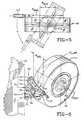
- a representative apparatus 10 (FIG 1) for applying a strip 12 (FIG. 4) of cushion gum to the crown surface 14 of a tyre carcass 16 employs a conventional extruder 18 which is operable to process cushion gum rubber compound "E” and to extrude the cushion gum compound "E” in a hot, viscous strip 12.
- the extruder 18 is mounted on a powered carriage 20 supported on rails 21 presented from a base 22 in order to permit selective fore and aft movement of the extruder 18 in the direction of arrow 24, as depicted in FIG. 1.
- Forward movement is arbitrarily selected to identify movement of the extruder 18 toward the tire carcass 16, as represented by the arrowhead 24 R facing to the right as viewed in FIG. 1, and rearward movement is designated as movement away from the tire carcass 16, as represented by the arrowhead 24 L which faces to the left as viewed in FIG. 1.
- the extruder 18 has a die head 26 which, as seen in FIGS. 2 through 4, is comprised of an upper die plate 28 and a lower die plate 30.
- the die head 26 is mounted at the outlet 32 of the extruder 18 by a rotary joint connection 34, as best depicted in FIG. 7.
- the configuration of the extrudate passage 36 and the configuration of the orifice 36 must cooperatively interact.
- the extrudate passage 36 enters the die head 26 as a single passage, as depicted, and then divides into divergent passageways 36 a and 36 2 which are transversely conjoined by passageway 36 3 which extends behind, and communicates with, the discharge orifice 38.
- a preferred structural configuration for an orifice 38 which cooperatively interacts with the aforesaid extrudate passage 36 will be described in detail immediately after the structural description of the die head 26 which follows.
- the upper die plate 28 has an outer, surface 40 that is concavely curved, as best seen in FIGS. 2 and 4, and which presents an abutment lip 42 that terminates in a further outwardly facing contact edge 44 that is also concavely curved so as to be disposed generally concentric to the concavely curved surface 40.
- the curvature profile of the contact edge 44 is selected to provide substantially full engagement with the crown surface 14 of the tire carcass 16 during substantially the entire range through which the die head 26 is expected to be rotated with minimal deformation to the tire carcass 16.
- the modestly required deformation is achieved by moving the powered carriage 20 to the right, in the direction designated by the arrowhead 24 R so that the contact surface 44 is driven against the crown surface 14. In that manner the apparatus 10 can readily accommodate various diameters of tire carcasses 16.
- the lower die plate 30 also has an outer surface 46 that is concavely curved, and which presents a further outwardly extending control lip 48 which terminates in a striking edge 50 that is generally concentric to the concavely curved surface 46.
- the striking edge 50 is concentrically displaced with respect to the abutment edge 44.
- the striking edge 50 is displaced from the full width of the crown surface 14 by a predetermined distance. This separation between the crown 14 and the striking edge 50 defines an extrudate accumulating space 52. It is into this accumulating space 52 that the extrudate "E" is forced from the discharge orifice 38 onto the crown surface 14 of the tire carcass as a strip 16.
- the discharge orifice 38 of the extrudate passage 36 may, as shown, be primarily formed in the lower die plate 30.
- the upper wall 54 of the discharge orifice 38 may be the generally planar undersurface of the upper die plate 28 which extends outward onto the underside of the abutment lip 42.
- the opposed surface of the discharge orifice 38 is primarily defined by a transversely arcuate surface 56 which has a relatively long radius.
- a discharge orifice 38 having a width of approximately 10.5 inches (26.67 cm) might well employ an arcuate surface 56 having a radius of approximately 48.29 inches (122.56 cm).
- the transverse ends of the arcuate surface 56 merge into linear surfaces 58A and 58B in the lower die plate 30.
- the linear surfaces 58 are preferably near parallel to the upper wall 54 of the discharge orifice 38 and they, in turn, terminate in the side walls 60A and 60B.
- the side walls 60 are perpendicular to the upper wall 54 and, in fact, will intersect the upper wall 54 when the die plates 28 and 30 are conjoined as a die head 26.
- a discharge orifice 38 having the configuration described will provide a substantially constant volumetric rate of extrudate "E" across the width of the die head 26, particularly when it receives the extrudate from a passageway 36 3 located immediately behind, and which extends the full extent of, the discharge orifice 38 -- the passageway 36 3 being supplied with extrudate from the passageways 36 1 and 36 2 which force the extrudate into the opposite ends of the passageway 36 3 .
- the flow path of the extrudate, together with the unique configuration of the discharge orifice 38, combine to provide the aforesaid constant volumetric discharge rate.
- the tire carcass 16 may be rotatably mounted on a hub 62 that is presented from a rotational control mechanism 64 which may, as is well known in the art, include a variable speed electric drive motor "M" (best shown in FIG. 8).
- the powered carriage 20 by which the extruder 18 is supported from the base 22 permits the extruder 18, and the die head 26, to be moved to the right in the direction of arrowhead 24 R and into modestly deformative abutment with the crown surface 14 on the tire carcass 16 when it is desired to extrude a single strip 12 of hot cushion gum which is thereby "wiped" onto the crown surface 14.
- the tire carcass 16 is rotated about the rotational axis R AXIS of the hub 62 by the rotational control mechanism 64 at a predetermined angular velocity.
- the angular velocity will contribute to the determination of the thickness of the single strip 12 of extruded hot cushion gum that is applied to the crown surface 14.
- the tire carcass 16 is rotated at a relatively high angular velocity; and, for a thicker strip of extrudate, the tire carcass 16 is rotated at a slower angular velocity.
- the thickness of the strip 12 applied to the crown surface 14 can be adjusted by controlling the angular velocity at which the tire carcass 16 is rotated.
- One exemplary means by which to adjust the angular velocity of the tire carcass 16 will now be described.
- a surface follower 66 (FIG. 8) may be supported from the rotational control mechanism 64 to abut the crown surface 14 of the tire carcass 16 and is operable, during the rotation of the tire carcass 16, to insure that the angular velocity of the tire carcass 16 remains within the desired limits to provide the desired thickness for the strip 12 of extruded cushion gum to be applied to the crown surface 14, as will be hereinafter more fully described.
- the representative apparatus 10 is adjustable to accommodate crown surface widths in the range of from about 10.5 inches (26.67 cm) to about 5.25 inches (13.48 cm). Therefore, as is best seen in FIG. 5, the apparatus 10 will apply a strip 12 of hot cushion gum to tire carcasses 16 having a range of from the maximum effective width, designated as W MAX on FIG. 5, to the minimum effective width designated as W MIN .
- the rotary joint connection 34 provides the means by which to select the desired effective width of the extruded strip 12, because the rotary joint connection 34 permits the die head 26 to be rotated through an angle ⁇ which, in the exemplary embodiment, is approximately 60 degrees.
- the die head 26 can be selectively positioned at any intermediate angle within the 60 degree angular range ⁇ , tire carcass 16 widths within a relatively wide range can be accommodated. It should be noted that the true width of the discharge orifice 38 does not change. Rather, the effective width is controlled by angling the die head 26 relative to the sagittal plane 68 (FIGS. 2 and 6) of the tire carcass 16.
- the maximum width of the strip 12 applied to the crown surface 14 occurs when the die head 26 is oriented at a right angle with respect to the sagittal plane 68. Conversely, the minimum width of a strip 12 applied to the crown surface 14 is achieved when the die head 26 is oriented at the maximum angle ⁇ with respect to the disposition of the die head 26 when the maximum strip width is applied to the crown surface 14.
- the rotary joint connection 34 includes a rotatable block 70, to which the die head 26 is secured, as by a plurality of cap screws 71, and a stationary block assembly 72, which is secured to the extruder 18 and from which the rotatable block 70 is supported.
- the stationary block assembly 72 includes a coupler 74 having first and second ends. The first end 76 of the coupler 74 cooperatively engages the outlet 32 of the extruder 18, and the second end 78 of the coupler 74 cooperatively engages the inlet 80 of the die head 26.
- the stationary block assembly 72 also includes a mounting plate 82 which fits over the conical body portion 84 of the coupler 74 to engage a mounting shoulder 86 which extends radially outwardly from the first end 76 of the conical body portion 84.
- a mounting plate 82 which fits over the conical body portion 84 of the coupler 74 to engage a mounting shoulder 86 which extends radially outwardly from the first end 76 of the conical body portion 84.
- the interior of the coupler 74 has a transitional passageway 94, with a larger aperture 96 at the first end 74 of the and a smaller aperture 98 at the second end 78.
- the larger aperture 96 communicates with the outlet 32 of the extruder 18 and the smaller aperture 98 communicates with the inlet 80 of the die head 18.
- a locating nut 100 is mounted on the threaded second end 78 of the coupler 74 to establish the orientation of the rotatable block 70 relative to the coupler 74 in the stationary block assembly 72.
- a lock washer 102 interacts between the second end 78 of the coupler 74 and the nut 100 to preclude rotation of the nut 100 relative to the stationary block assembly 72.
- a thrust washer 104 is disposed between the lock washer 102 and the rotatable block 70 to permit relative rotation therebetween without imposing significant rotationally induced frictional forces on the lock washer 102, and thus the locating nut 100.
- the die head 26 is spaced outwardly of the second end 78 of the coupler 74 approximately 0.001 to 0.003 inches (0.025 to 0.076 mm), and an annular seal 105 is interposed between the die head 26 and the coupler 74.
- the rotatable block 70 has a substantially cylindrical outer surface 106 on which a reference cam 108 is secured.
- the reference cam 108 is useful in establishing a signal representing the angular disposition of the die head 26, which signal is provided to a microprocessor 110 that is represented diagrammatically in FIG. 8, the purpose of which will become hereinafter more apparent.
- a handle 112 is presented from the die head 26 to provide a means by which an operator may manually rotate the die head 26 about the central axis 113 of the stationary block assembly 72 to the desired angular position within the angular range ⁇ . That is, the operator will rotate the die head 26 to the desired angular position so that the selected width W SEL (FIG. 6) of the strip 12 will match the width of the crown surface 14 for the specific tire carcass 16 to be presented against the contact edge 44 on the abutment lip 42.
- the rotational control mechanism 64 is in communication with the microprocessor 110 by virtue of a conventional encoder 114.
- the encoder 114 is actuated by the follower 66 in order to provide an input signal to the microprocessor 110 which reflects the exact angular velocity of the tire carcass 16.
- the microprocessor 110 also receives an input signal relative to the exact angle ⁇ that has been set within the angular range ⁇ through which the die head 26 can be rotated.
- the specific angle, such as ⁇ , through which the die head 26 has been rotated may be read from a potentiometer 116 which is controlled by a composite pinion gear 118 that is, in turn, driven by a rack 120.
- the rack 120 may comprise the outer surface of a cam follower 122 which is maintained in abutment with the reference cam 108.
- the reference cam 108 will be rotated therewith to drive the cam follower 122, and the rack 120, linearly, thereby effecting rotation of the pinion gear 118.
- the pinion gear 118 is operatively connected to the potentiometer 116 such that rotation of the pinion gear 118 generates a potential that is read by the potentiometer 116 and fed, as an input data signal to the microprocessor 110. Because of the means by which the signal is generated, the signal reflects the angular disposition ⁇ of the die head 26.
- the microprocessor 110 has the necessary information to establish the basic angular velocity for the tire carcass 16 and will set the rotational control mechanism 62 accordingly.
- the microprocessor 110 may be a conventionally programmable electronic device in the nature of a digital computer programmed with an algorithm which causes the microprocessor 110 to respond to signals received from the encoder 114 and the potentiometer 116 and to generate an appropriate output signal to the rotational control mechanism 64 which effects the desired angular velocity of the tire carcass 16.
- the microprocessor 110 may also receive input data from a conventional keyboard 124 that is incorporated on the microprocessor 110.
- the microprocessor 110 may also incorporate a digital display 126 which provides a visual representation of the data entered by the keyboard 124 and/or any other information received, or generated, by the microprocessor 110.
- the desired thickness of the strip 12 may be entered through the keyboard 124 and the microprocessor 110 feeds an output signal, as determined by the input signals and processed in accordance with a preprogrammed algorithm, to a conventional variable speed drive control 128 which establishes the angular velocity to be developed by the rotational control mechanism 64 and, therefore, the tire carcass 16.
- FIG. 8 illustrates the input signals to the microprocessor 110 and the output signal from the microprocessor 110. It should be readily appreciated that this system, with the various feedback signals, will control the hot cushion gum strip laying process.
- a position sensor 130 may, as shown, be disposed on the die head 26, or be otherwise mounted relative thereto.
- the position sensor 130 determines when the leading edge 132 of the cushion gum strip 12 is approaching the contact edge 44 on the abutment lip 42.
- a signal is generated by the sensor 130 which is employed to stop the extrusion process and displace the extruder 18 along the base 22 so as to remove the die head 26 from abutment with the crown surface 14 on the tire carcass 16.
- the continued rotation of the tire carcass 16 acts to stretch and separate the strip 12 of extrudate, thereby producing a splice 134 between the leading edge 132 and the trailing edge 136, which is formed by the separation of the strip 12.
- the splice 134 produced by the engagement of the leading and trailing edges 132 and 136, respectively can take the form of an end-to-end splice 134 A , or, as shown in FIG. 10, an overlap splice 134 B .
- the outer surface 138 of the cushion gum strip is smooth.
- An overlap splice 134 B produces a modest protuberance 140 caused by the remnants of the trailing edge 136 extending circumferentially beyond the leading edge 134.
- the single strip 12 is extruded and applied in a hot condition to a buffed crown surface 14, eliminating the need for application of adhesives or cements prior to the application of the strip 12. Because the strip 12 of cushion gum is applied in a hot condition, the cushion gum will impregnate the crown surface 14 of the tyre carcass 16 providing excellent adhesion, or bonding, between the carcass 16 and the cushion gum strip 12.
- the preparation of a tyre carcass 16 for retreading with a single strip 12 of cushion gum may be accomplished by the unique process which the apparatus 10 is adapted to perform.
- the process begins by mounting a tyre carcass 16 for rotation about the central axis 113 and then bringing the crown surface 14 of the carcass 16 into an operative disposition relative to a die head 26 that has been oriented to present a strip 12 of extrudate having a width W SEL equal to the width of the crown surface 14.
- the cushion gum By rotating the tyre carcass 16 at a controlled angular velocity, and simultaneously extruding a strip 12 of hot cushion gum onto the crown surface 14 of the carcass 16 for a single revolution of the carcass 16, the cushion gum can be applied as a single, accurate layer.
Landscapes
- Engineering & Computer Science (AREA)
- Mechanical Engineering (AREA)
- Manufacturing & Machinery (AREA)
- Tyre Moulding (AREA)
- Extrusion Moulding Of Plastics Or The Like (AREA)
Claims (15)
- Un appareil pour appliquer un bandage chaud (E) dans une couche d'épaisseur et de largeur prédéterminées à la surface de couronne (14) d'une carcasse de pneumatique (16) ayant un plan sagittal (68), l'appareil (10) comprenant un moyen (M) pour faire tourner la carcasse de pneumatique (16), un moyen d'extrusion (18) pour délivrer le bandage chaud (E), un moyen à filière (26) et un passage interne (36) dans le moyen à filière (26) pour acheminer le bandage chaud (E) à partir du moyen d'extrusion (18) et former une bande (12) ayant une largeur globale prédéterminée; caractérisé par un moyen (34) pour disposer sélectivement angulairement le moyen à filière (26) par rapport au plan sagittal (68) de la carcasse de pneumatique (16) pour déterminer la largeur de la bande (12) lorsqu'elle est appliquée à la surface de couronne (14) de la carcasse de pneumatique (16) à partir du moyen à filière (26).
- Un appareil selon la revendication 1, dans lequel le moyen (34) pour disposer sélectivement angulairement le moyen à filière (26) par rapport au plan sagittal (68) de la carcasse de pneumatique (16) comprend un moyen de liaison rotatif (34) interposé entre le moyen d'extrusion (18) et le moyen à filière (26).
- Un appareil selon la revendication 2, dans lequel le moyen de liaison rotatif (34) comprend un moyen à bloc apte à tourner (70) fixé au moyen à filière (26), un moyen à bloc fixe (72) fixé au moyen d'extrusion (18) et un moyen de couplage (74) reliant entre eux le moyen à bloc apte à tourner (70) et le moyen à bloc fixe (72).
- Un appareil selon la revendication 3, comprenant un moyen à came (108) sur le moyen à bloc apte à tourner (70) pour établir un signal proportionnel à la disposition angulaire du moyen à filière (26) par rapport au plan sagittal (68) de la carcasse de pneumatique (16).
- Un appareil selon l'une quelconque des revendications précédentes, dans lequel le moyen à filière (26) présente une première surface incurvée (44) agencée pour être disposée près de la surface de couronne (14) de la carcasse de pneumatique (16), une deuxième surface incurvée (50) sur le moyen à filière (26) étant agencée pour être disposée selon une relation espacée à partir de la surface de couronne (14) de la carcasse de pneumatique (16), le passage interne (36) débouchant entre les première (44) et seconde (50) surfaces incurvées.
- Un appareil selon la revendication 5, dans lequel des moyens (20) sont prévus pour amener la première surface incurvée (44) en contact de déformation avec la surface de couronne (14) sur la carcasse de pneumatique (16).
- Un appareil selon la revendication 6, dans lequel la deuxième surface incurvée (50) est sensiblement concentrique avec la première surface incurvée (44).
- Un appareil selon l'une quelconque des revendications précédentes, comprenant, en outre un moyen (128) pour commander sélectivement la vitesse angulaire du moyen de rotation de carcasse (M) pour faire tourner la carcasse de pneumatique (16) afin de déterminer l'épaisseur de la bande (12) appliquée à la surface de couronne (14) de la carcasse de pneumatique (16).
- Un appareil selon la revendication 8, comprenant, en outre, un moyen (116) pour fournir un signal proportionnel à la disposition angulaire du moyen à filière (26) par rapport au plan sagittal (68) de la carcasse de pneumatique (16) au moyen (110) pour commander la vitesse de rotation de la carcasse de pneumatique (16), le moyen (110) pour commander la vitesse de rotation de la carcasse de pneumatique réagissant, en partie au signal proportionnel à la disposition angulaire du moyen à filière (26) pour produire un signal de sortie.
- Un appareil selon la revendication 9, dans lequel le moyen de commande sélectif (128) réagit au signal de sortie produit par le moyen de commande de vitesse de rotation (110) pour commander la vitesse angulaire du moyen de rotation de carcasse (M) afin de fournir une épaisseur prédéterminée de la couche de bandage chaud à la surface de couronne (14) de la carcasse de pneumatique (16).
- Un appareil selon l'une quelconque des revendications précédentes, comprenant en outre un moyen (130) pour détecter un bord antérieur (132) de la bande (12) de bandage chaud (E) pour commander l'opération du moyen d'extrusion (18).
- Un procédé pour appliquer une bande (12) de bandage chaud (E) à la surface de couronne (14) d'une carcasse de pneumatique (16) comprenant les étapes de montage de la carcasse de pneumatique (16) ayant une surface de couronne circonférentielle extérieure (14) de largeur prédéterminée devant être recouverte avec une seule couche du bandage chaud (E), de présentation d'une tête de filière d'extrusion (26) à la surface de couronne (14) d'amenée de la tête de filière (26) selon une juxtaposition contigue avec la surface de couronne (14), de rotation de la carcasse de pneumatique (16) à une vitesse angulaire prédéterminée et d'extrusion du bandage chaud (E) à travers la tête de filière (26) sur la surface de couronne (14) de la carcasse de pneumatique (16); caractérisé par l'étape supplémentaire de positionnement sélectif de la tête de filière selon un angle par rapport à la surface de couronne avec un moyen (34) pour disposer ainsi sélectivement angulairement la tête de filière (26) pour établir la largeur efficace désirée de la bande (12) appliquée par la tête de filière (26) à la surface de couronne (14).
- Un procédé selon la revendication 12, comprenant les étapes supplémentaires de coordination du taux auquel le bandage (E) est extrudé et de la vitesse angulaire à laquelle la carcasse de pneumatique (16) est amenée à tourner pour contrôler l'épaisseur de la bande (12) appliquée à la surface de couronne (14) de la carcasse de pneumatique (16).
- Un procédé selon la revendication 12 ou la revendication 13, comprenant l'étape supplémentaire d'entraînement de la tête de filière (26) selon un contact de déformation avec la surface de couronne (14) de la carcasse de pneumatique (16) avant l'extrusion du bandage (E).
- Un procédé selon l'une quelconque des revendications 12 à 14, comprenant les étapes supplémentaires de détection de la position d'un bord antérieur (132) de la bande (12) en un emplacement prédéterminé et d'arrêt de l'extrusion et de retrait de la tête de filière (26) à partir de la surface de couronne (14) en réaction à la position détectée du bord antérieur (132).
Applications Claiming Priority (2)
| Application Number | Priority Date | Filing Date | Title |
|---|---|---|---|
| US747809 | 1985-06-21 | ||
| US07/747,809 US5342473A (en) | 1991-08-20 | 1991-08-20 | Apparatus for applying hot cushion gum to a tire carcass |
Publications (2)
| Publication Number | Publication Date |
|---|---|
| EP0528683A1 EP0528683A1 (fr) | 1993-02-24 |
| EP0528683B1 true EP0528683B1 (fr) | 1997-03-12 |
Family
ID=25006739
Family Applications (1)
| Application Number | Title | Priority Date | Filing Date |
|---|---|---|---|
| EP92307568A Expired - Lifetime EP0528683B1 (fr) | 1991-08-20 | 1992-08-19 | Procédé et dispositif pour appliquer à chaud un bandage en caoutchouc sur une carcasse de pneu |
Country Status (3)
| Country | Link |
|---|---|
| US (2) | US5342473A (fr) |
| EP (1) | EP0528683B1 (fr) |
| JP (1) | JPH05229034A (fr) |
Families Citing this family (35)
| Publication number | Priority date | Publication date | Assignee | Title |
|---|---|---|---|---|
| DE9314733U1 (de) * | 1993-08-05 | 1994-06-30 | A-Z Formen- und Maschinenbau GmbH, 80992 München | Runderneuerungsvorrichtung |
| AU676379B2 (en) * | 1993-08-05 | 1997-03-06 | A-Z Formen Und Maschinenbau Gmbh | Retreading device |
| IL117357A (en) * | 1995-03-08 | 1999-09-22 | Bandag Inc | Retreaded tires and method for making the same without spray cement |
| US5635015A (en) * | 1995-03-29 | 1997-06-03 | Hercules Tire And Rubber Company | Apparatus for cementless building of retreaded tires |
| DE29612955U1 (de) * | 1996-07-25 | 1996-09-19 | Az Formen & Maschbau Gmbh | Runderneuerungsvorrichtung |
| JP4420491B2 (ja) * | 1998-06-29 | 2010-02-24 | 株式会社ブリヂストン | タイヤ構成部材用ゴム材料の張付方法及び張付装置 |
| US6899778B1 (en) | 2000-01-27 | 2005-05-31 | Bandag Incorporated | Method and apparatus for preparing tire tread for a retread tire |
| US6758931B1 (en) | 2000-01-27 | 2004-07-06 | Bandag, Incorporated | Method and apparatus for applying tire tread for a retread tire |
| JP2002160284A (ja) | 2000-11-22 | 2002-06-04 | Bridgestone Corp | タイヤ用ゴム材料の押出方法及び押出装置 |
| JP2006500250A (ja) * | 2002-09-25 | 2006-01-05 | ソシエテ ド テクノロジー ミシュラン | タイヤの製造のために移動表面にゴム混合物を塗布するための装置 |
| US7052568B2 (en) * | 2002-10-28 | 2006-05-30 | Bridgestone Firestone North American Tire, Llc | Tire retreading method |
| US20040089400A1 (en) * | 2002-11-08 | 2004-05-13 | Vargo Richard David | Method and apparatus for forming an annular elastomeric tire component |
| BRPI0419074B1 (pt) * | 2004-09-30 | 2014-01-21 | Método e aparelho para fabricação pneus | |
| US7497241B2 (en) * | 2005-07-27 | 2009-03-03 | The Steelastic Company, Llc | Tire belt machine |
| EP1749648A3 (fr) * | 2005-08-04 | 2007-10-24 | The Goodyear Tire & Rubber Company | Procédé et dispositif pour l'application d'une bande élastomère sur une surface |
| US20070031529A1 (en) * | 2005-08-04 | 2007-02-08 | Koch Brian R | Apparatus for forming elastomeric tire component and a tire |
| US7780809B2 (en) * | 2005-08-04 | 2010-08-24 | The Goodyear Tire & Rubber Company | Method for forming elastomeric tire component and a tire |
| BRMU8601440Y1 (pt) * | 2006-07-10 | 2021-07-06 | Borrachas Vipal S.A. | Novas disposições em corpo-suporte universal para coberturas pneumáticas |
| US8683941B2 (en) * | 2007-05-11 | 2014-04-01 | Michelin Recherche Et Technique S.A. | Articulated nozzle |
| US9539778B2 (en) * | 2007-11-28 | 2017-01-10 | The Goodyear Tire & Rubber Company | Pneumatic tire and a process to retread a tire |
| CN101980852B (zh) * | 2008-03-31 | 2014-08-13 | 米其林研究和技术股份有限公司 | 将减震胶涂覆至外胎的方法和装置 |
| WO2011002448A1 (fr) | 2009-06-30 | 2011-01-06 | Societe De Technologie Michelin | Pneumatique rechapé comportant une bande de chape adaptée à une chape de base |
| US20110126961A1 (en) | 2009-12-02 | 2011-06-02 | Bridgestone Bandag, Llc | Passive buffer brush air cooling |
| JP5415987B2 (ja) * | 2010-02-12 | 2014-02-12 | 株式会社ブリヂストン | タイヤ製造装置及びタイヤ製造方法 |
| US20130276944A1 (en) * | 2010-12-29 | 2013-10-24 | Compagnie Generale Des Etablissements Michelin | Custom pre-cured retread |
| US9370971B2 (en) | 2010-12-29 | 2016-06-21 | Compagnie Generale Des Etablissements Michelin | Methods for retreading a tire |
| CN102896793A (zh) * | 2011-07-25 | 2013-01-30 | 孙玉和 | 巨型轮胎翻新刻花设备 |
| WO2015100052A1 (fr) | 2013-12-24 | 2015-07-02 | Bridgestone Americas Tire Operations, Llc | Pneu doté d'une ceinture ayant une bandelette enveloppante de gomme de liaison |
| US20150217522A1 (en) * | 2014-02-04 | 2015-08-06 | Vikrant Ragula | Methods and devices for improving usable life of wearable surfaces |
| CN106393761A (zh) * | 2015-08-10 | 2017-02-15 | 青岛软控机电工程有限公司 | 一种中垫胶挤出机 |
| US11148381B2 (en) * | 2015-08-20 | 2021-10-19 | Bridgestone Americas Tire Operations, Llc | Methods for manufacturing a tread for agricultural tire using a dinitrile oxide cure system |
| US20180244007A1 (en) * | 2015-08-20 | 2018-08-30 | Bridgestone Americas Tire Operations, Llc | Methods for retreading tires employing cushion gum with stable dinitrile oxide cure system |
| US11247424B1 (en) * | 2016-12-13 | 2022-02-15 | Bridgestone Americas Tire Operations, Llc | Methods for retreading tires |
| FR3067281B1 (fr) * | 2017-06-09 | 2020-01-17 | Compagnie Generale Des Etablissements Michelin | Systeme de fabrication d’une bande de roulement |
| CN114211795B (zh) * | 2021-12-21 | 2023-05-12 | 马牌科技(东莞)有限公司 | 一种高分子材料平衡车轮胎制作工艺及设备 |
Family Cites Families (8)
| Publication number | Priority date | Publication date | Assignee | Title |
|---|---|---|---|---|
| US3459613A (en) * | 1965-07-29 | 1969-08-05 | American Air Filter Co | Method and apparatus for making filamentous mat |
| US3808076A (en) * | 1970-05-07 | 1974-04-30 | J Barwell | Methods and apparatus for applying tread to tyres or wheels |
| GB1590378A (en) * | 1976-07-26 | 1981-06-03 | Barwell P R G | Apparatus for applying tread material to tyres |
| US4240863A (en) * | 1979-04-12 | 1980-12-23 | Caterpillar Tractor Co. | Control system for an elastomer extrusion and applicator apparatus |
| EP0056704B1 (fr) * | 1981-01-21 | 1986-08-20 | Alcan International Limited | Dispositif et procédé pour appliquer un enduit |
| DE3541126A1 (de) * | 1985-11-13 | 1987-05-14 | Ihle Reifen Gmbh | Verfahren und vorrichtung zum aufbringen eines rohgummibelags auf eine karkasse |
| DE4012695C2 (de) * | 1990-04-20 | 2001-08-02 | Az Formen & Maschbau Gmbh | Bindegummiextruder |
| US5129356A (en) * | 1990-05-29 | 1992-07-14 | Brown & Williamson Tobacco Corporation | Fluid applicator |
-
1991
- 1991-08-20 US US07/747,809 patent/US5342473A/en not_active Expired - Fee Related
-
1992
- 1992-08-19 EP EP92307568A patent/EP0528683B1/fr not_active Expired - Lifetime
- 1992-08-20 JP JP4242519A patent/JPH05229034A/ja active Pending
-
1994
- 1994-08-26 US US08/296,526 patent/US5447587A/en not_active Expired - Fee Related
Also Published As
| Publication number | Publication date |
|---|---|
| JPH05229034A (ja) | 1993-09-07 |
| US5342473A (en) | 1994-08-30 |
| EP0528683A1 (fr) | 1993-02-24 |
| US5447587A (en) | 1995-09-05 |
Similar Documents
| Publication | Publication Date | Title |
|---|---|---|
| US5342473A (en) | Apparatus for applying hot cushion gum to a tire carcass | |
| EP0080968B1 (fr) | Bandage pneumatique et procédé pour appliquer une couche obturante | |
| US5456785A (en) | Composite roofing product and method and apparatus for making a composite roofing product | |
| KR840000210B1 (ko) | 타이어에 폭이 좁은 스트립 소재를 적용하기 위한 장치 | |
| EP0619170B1 (fr) | Procédé et dispositif pour la fabrication d'une feuille caoutchoutée renforcée par fils | |
| US7641752B2 (en) | Process for laying a strip continuously on a toroidal surface | |
| US5273601A (en) | Method and device for cutting to length a strip of tire building material | |
| US8365791B2 (en) | Method and apparatus of adhering belt edge tape | |
| WO2003070453A1 (fr) | Procede de production d'element en caoutchouc mince, dispositif de calandrage de caoutchouc, et procede de calandrage de caoutchouc | |
| JPH0368261B2 (fr) | ||
| EP0796169B1 (fr) | Procede de revetement et systeme de commande pour revetement | |
| US12576607B2 (en) | Splice-match builder | |
| GB2234718A (en) | Retreading tires | |
| US6899778B1 (en) | Method and apparatus for preparing tire tread for a retread tire | |
| US6758931B1 (en) | Method and apparatus for applying tire tread for a retread tire | |
| JPH03132333A (ja) | 推進装置の熱保護ライニング形成方法および形成装置 | |
| US20040256057A1 (en) | Method and apparatus for retreading tires | |
| CN115042263B (zh) | 一种输送带钢丝绳芯分离方法 | |
| JPS6034818A (ja) | タイヤ用未加硫ゴム部品の製造方法及び装置 | |
| AU676379B2 (en) | Retreading device | |
| GB2132573A (en) | Manufacture of rubber layers or ply fabric for reinforced articles e.g. pneumatic tyres | |
| CA2790019C (fr) | Methode et appareillage pour la preparation de bandes de roulement destinees aux pneus rechappes | |
| EP1120234A2 (fr) | Procédé et dispositif pour appliquer une bande en caoutchouc sur une carcasse de pneumatique | |
| KR840000211B1 (ko) | 타이어에 폭이 좁은 스트립 소재를 적용하기 위한 방법 | |
| JPH0557218A (ja) | 空気入りタイヤのインナーライナー及びタイヤ内面塗装剤塗布装置 |
Legal Events
| Date | Code | Title | Description |
|---|---|---|---|
| PUAI | Public reference made under article 153(3) epc to a published international application that has entered the european phase |
Free format text: ORIGINAL CODE: 0009012 |
|
| AK | Designated contracting states |
Kind code of ref document: A1 Designated state(s): FR IT SE |
|
| 17P | Request for examination filed |
Effective date: 19930818 |
|
| 17Q | First examination report despatched |
Effective date: 19941207 |
|
| GRAG | Despatch of communication of intention to grant |
Free format text: ORIGINAL CODE: EPIDOS AGRA |
|
| GRAH | Despatch of communication of intention to grant a patent |
Free format text: ORIGINAL CODE: EPIDOS IGRA |
|
| GRAH | Despatch of communication of intention to grant a patent |
Free format text: ORIGINAL CODE: EPIDOS IGRA |
|
| GRAA | (expected) grant |
Free format text: ORIGINAL CODE: 0009210 |
|
| AK | Designated contracting states |
Kind code of ref document: B1 Designated state(s): FR IT SE |
|
| ET | Fr: translation filed | ||
| ITF | It: translation for a ep patent filed | ||
| PLBE | No opposition filed within time limit |
Free format text: ORIGINAL CODE: 0009261 |
|
| STAA | Information on the status of an ep patent application or granted ep patent |
Free format text: STATUS: NO OPPOSITION FILED WITHIN TIME LIMIT |
|
| 26N | No opposition filed | ||
| PGFP | Annual fee paid to national office [announced via postgrant information from national office to epo] |
Ref country code: SE Payment date: 19990804 Year of fee payment: 8 |
|
| PGFP | Annual fee paid to national office [announced via postgrant information from national office to epo] |
Ref country code: FR Payment date: 19990810 Year of fee payment: 8 |
|
| PG25 | Lapsed in a contracting state [announced via postgrant information from national office to epo] |
Ref country code: SE Free format text: LAPSE BECAUSE OF NON-PAYMENT OF DUE FEES Effective date: 20000820 |
|
| EUG | Se: european patent has lapsed |
Ref document number: 92307568.3 |
|
| PG25 | Lapsed in a contracting state [announced via postgrant information from national office to epo] |
Ref country code: FR Free format text: LAPSE BECAUSE OF NON-PAYMENT OF DUE FEES Effective date: 20010430 |
|
| REG | Reference to a national code |
Ref country code: FR Ref legal event code: ST |
|
| PG25 | Lapsed in a contracting state [announced via postgrant information from national office to epo] |
Ref country code: IT Free format text: LAPSE BECAUSE OF NON-PAYMENT OF DUE FEES;WARNING: LAPSES OF ITALIAN PATENTS WITH EFFECTIVE DATE BEFORE 2007 MAY HAVE OCCURRED AT ANY TIME BEFORE 2007. THE CORRECT EFFECTIVE DATE MAY BE DIFFERENT FROM THE ONE RECORDED. Effective date: 20050819 |