EP0529214A2 - Presse à doubles bandes - Google Patents
Presse à doubles bandes Download PDFInfo
- Publication number
- EP0529214A2 EP0529214A2 EP92109516A EP92109516A EP0529214A2 EP 0529214 A2 EP0529214 A2 EP 0529214A2 EP 92109516 A EP92109516 A EP 92109516A EP 92109516 A EP92109516 A EP 92109516A EP 0529214 A2 EP0529214 A2 EP 0529214A2
- Authority
- EP
- European Patent Office
- Prior art keywords
- press
- plate
- shape
- pressure
- plates
- Prior art date
- Legal status (The legal status is an assumption and is not a legal conclusion. Google has not performed a legal analysis and makes no representation as to the accuracy of the status listed.)
- Granted
Links
Images



Classifications
-
- B—PERFORMING OPERATIONS; TRANSPORTING
- B27—WORKING OR PRESERVING WOOD OR SIMILAR MATERIAL; NAILING OR STAPLING MACHINES IN GENERAL
- B27N—MANUFACTURE BY DRY PROCESSES OF ARTICLES, WITH OR WITHOUT ORGANIC BINDING AGENTS, MADE FROM PARTICLES OR FIBRES CONSISTING OF WOOD OR OTHER LIGNOCELLULOSIC OR LIKE ORGANIC MATERIAL
- B27N3/00—Manufacture of substantially flat articles, e.g. boards, from particles or fibres
- B27N3/08—Moulding or pressing
- B27N3/24—Moulding or pressing characterised by using continuously acting presses having endless belts or chains moved within the compression zone
-
- B—PERFORMING OPERATIONS; TRANSPORTING
- B30—PRESSES
- B30B—PRESSES IN GENERAL
- B30B15/00—Details of, or accessories for, presses; Auxiliary measures in connection with pressing
- B30B15/06—Platens or press rams
- B30B15/061—Cushion plates
-
- B—PERFORMING OPERATIONS; TRANSPORTING
- B30—PRESSES
- B30B—PRESSES IN GENERAL
- B30B5/00—Presses characterised by the use of pressing means other than those mentioned in the preceding groups
- B30B5/04—Presses characterised by the use of pressing means other than those mentioned in the preceding groups wherein the pressing means is in the form of an endless band
- B30B5/06—Presses characterised by the use of pressing means other than those mentioned in the preceding groups wherein the pressing means is in the form of an endless band co-operating with another endless band
-
- B—PERFORMING OPERATIONS; TRANSPORTING
- B30—PRESSES
- B30B—PRESSES IN GENERAL
- B30B7/00—Presses characterised by a particular arrangement of the pressing members
- B30B7/02—Presses characterised by a particular arrangement of the pressing members having several platens arranged one above the other
-
- Y—GENERAL TAGGING OF NEW TECHNOLOGICAL DEVELOPMENTS; GENERAL TAGGING OF CROSS-SECTIONAL TECHNOLOGIES SPANNING OVER SEVERAL SECTIONS OF THE IPC; TECHNICAL SUBJECTS COVERED BY FORMER USPC CROSS-REFERENCE ART COLLECTIONS [XRACs] AND DIGESTS
- Y10—TECHNICAL SUBJECTS COVERED BY FORMER USPC
- Y10T—TECHNICAL SUBJECTS COVERED BY FORMER US CLASSIFICATION
- Y10T156/00—Adhesive bonding and miscellaneous chemical manufacture
- Y10T156/17—Surface bonding means and/or assemblymeans with work feeding or handling means
- Y10T156/1702—For plural parts or plural areas of single part
- Y10T156/1712—Indefinite or running length work
- Y10T156/1741—Progressive continuous bonding press [e.g., roll couples]
Definitions
- the invention relates to a shape compensation plate according to the preamble of claim 1 or a continuously operating double belt press for the production of endless material webs such as laminates, chipboard or fiberboard, plywood or the like according to the preamble of claim 18 or a discontinuously working single or multi-day press for production of section-shaped materials according to the preamble of claim 24.
- Double belt presses are used for the continuous production of endless web-shaped materials, in particular for the production of decorative laminate laminates, copper-clad electrical laminates, thermoplastic webs, chipboard, fiberboard and the like.
- These double belt presses have two endless rotating press belts, between which the material web is cured under the action of pressure and possibly also heat while being transported in the forward direction.
- pressure plates are arranged in the press frame of the double belt press, from which the pressure is transmitted to the inside of the press belts and from these to the material web.
- ring-shaped, self-contained sliding surface seals are arranged along the edge region of the pressure plate, which are applied to the press belt with one surface such that the press belt slides along this surface during operation of the double belt press.
- This creates pressure chambers that are delimited in the vertical direction by the pressure plate and the inside of the press belt and in the horizontal direction by the sliding surface seals.
- a fluid pressure medium for example oil or compressed air, is introduced into these pressure plates.
- Such isobaric double belt presses are known for example from DE-PS 27 22 197.
- the pressure is mechanically transferred from the pressure plate to the inside of the press belt via rollers.
- a fixed roller bed arranged in the pressure plate is known from DE-OS 31 23 291.
- the roller bed consists of rollers arranged offset from one another, which are mounted in bearing blocks by means of shafts, these bearing strips in turn being fastened in the pressure plate.
- a double belt press which combines the isobaric and the isochoric principle.
- the roller bed is arranged in a pressure pad which is sealed on the side by sliding surface seals.
- This double belt press can be operated purely isochorously, in that only the roller bed is placed against the press belt, without a pressurized fluid pressure medium being introduced into the pressure pad.
- a purely isobaric mode of operation is also possible in that the roller bed is not placed against the press belt, but only a fluid pressure medium maintains the pressure in the pressure pad.
- isobar / isochor both the roller bed is placed against the press belt and a pressurized fluid pressure medium is introduced into the pressure pad.
- a further pressure chamber is used to exert pressure on the roller bed.
- This is arranged on the side of the pressure plate facing away from the press belt and is delimited in the vertical direction by the pressure plate and a closure located in the press frame, and in the horizontal direction by side seals which are designed in the same way as the sliding surface seals for the pressure pad.
- a disadvantage of this known design of a double belt press that can be operated isobarically / isochorously is that leakage of fluid pressure medium can occur on the side seals of the pressure chamber arranged on the side of the pressure plate facing away from the press belt, in particular at higher pressures, and can contaminate the press frame and the material to be pressed .
- the material to be pressed often requires treatment during the pressing at elevated temperature. To do this, the printing plate is heated to the required temperature.
- the known sealing materials for the side seals consist of plastic or elastomers, which are only resistant up to temperatures of approx. 270 0C. At higher temperatures, the side seals of this pressure chamber are therefore destroyed, which ultimately leads to the failure of the pressurization by the pressure chamber and thus to a time-consuming and costly repair of the double belt press. This double belt press is therefore not suitable for use at higher temperatures.
- the invention is based, to develop the isochoric or combined isochoric / isobar double belt press so that it can be used reliably at elevated temperatures.
- the advantages that can be achieved with the invention are, in particular, that no leakage of pressure medium can occur in the shape-compensating plate according to the invention due to the hermetic lateral edge seal. Contamination of the press and the material to be pressed is therefore excluded with certainty.
- the shape compensation plate contains no plastics, so that the double belt press can also be used for high temperatures. With the help of the shape compensation plate, deflections in the pressing area of the double belt press, in particular the press frame, are compensated, as a result of which a better dimensionally stable product is produced on the double belt press.
- the shape-adjustment plate contains a metallic liquid as the fluid pressure medium.
- Metallic liquids have a very good thermal conductivity, so that unhindered heat transfer between the press belts and a heat exchange plate located plane-parallel in the press frame is guaranteed. This leads to a qualitatively improved pressed product and allows the double belt press to be operated at higher speeds.
- the shape compensation plate is divided into a plurality of individual strip-shaped shape adjustment plates lying next to one another. This gives you the opportunity to process pressed material with different widths in the double belt press.
- the shape-compensating plate according to the invention can be used successfully not only in continuously operating double belt presses but also in discontinuously operating single or multi-day presses. Such a single or multi-day press is described by the technical teaching contained in the characterizing part of patent claim 7.
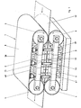
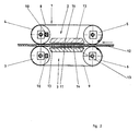
- the continuously operating double belt press 1 shown in FIGS. 1 and 2 consists of an upper press belt unit 2 and a lower press belt unit 3, which are arranged one above the other.
- the press belt units 2, 3 in turn consist of two each, in bearing bridges 38, 39 rotatably mounted deflection drums 4, 5 or 6, 7 and an endless press belt 8, 9 together.
- the press belt 8, 9, which usually consists of a high-tensile steel band, is guided around the deflection drums 4, 5 or 6, 7 and tensioned by means of hydraulic cylinders 10 arranged in the bearing bridges 38, 39.
- At least one deflection drum of each press belt unit 2, 3 is driven by a motor, so that the two press belts 8, 9 move according to the arrows in the deflection drums 5, 6.
- the bearing bridges 38, 39 are fastened to the press frame 40, 41, which is schematically indicated in FIG. 1.
- the press frame 40, 41 is not shown in Figure 2 for reasons of clarity.
- the detailed design of the press frame can be found, for example, in DE-OS 32 34 082.
- reaction zone 11 Between the lower belt run of the upper press belt 8 and the upper belt run of the lower press belt 9 lies the reaction zone 11, in which the material web 12 leading from right to left in the drawings is pressed under surface pressure during the passage through the double belt press 1.
- pressure plates 13 are arranged in the press frame 40, 41 of the double belt press 1, of which the surface pressure is mechanically applied to the inside of the press belts 8, 9 and then transferred by them to the material web 12 , which is an isochoric double belt press.
- a roller bed consisting of stationary rollers 14 is used to generate the mechanical surface pressure between the pressure plate 13 and the inside of the press belt 8, 9.
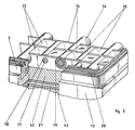
- roller bed used for the mechanical pressure transmission can be seen in more detail in FIG. 3 in a perspective view.
- 13 support bearing strips 16 are arranged in the pressure plate.
- support bearing strips 16 there are support shafts 17 on which the rollers 14 are arranged in rows parallel to the feed direction of the press belts 8, 9.
- the rollers 14 have a smaller length than the width of the pressure plate 13, so that a plurality of rollers 14 are arranged side by side on a support shaft 17.
- the rollers 14 are in two adjacent rows half a roller width offset from each other by replacing every second support bearing bore 18 with an opening 19 which is slightly larger than the diameter of the roller 14.
- the roller bed can additionally be surrounded by one or more sliding surface seals 20, which are arranged in the pressure plate 13 and are applied to the pressing belt 8, 9 with one surface, so that the pressing belt 8, 9 slides along these sliding surface seals 20.
- the sliding surface seal 20 is closed in a ring shape, so that the roller bed lies in an enclosed space and can be filled with lubricant for the rollers.
- the cavity between two rollers 14 can also be provided with a filler 15 in order to improve the lubrication by forming capillary gaps between the roller 14, the support bearing strips 16 and the pressure plate 13.
- the space enclosed by the sliding surface seal 20 can also be provided with a fluid pressure medium, which additionally exerts a hydraulic pressure on the inside of the press belts 8, 9. Such a configuration is then a double belt press working in a combined isobar / isochoric manner.
- the pressure plate 13 consists of a carrier plate 42 in which the support bearing strips 16 for the roller bed are fastened, an adjoining shape compensation plate 21 and a rigid heat exchange plate 43.
- the carrier plate 42 is preferably of flexible design.
- the heat exchange plate 43 there are bores 44 through which a fluid heat transfer medium can flow. As a result, the heat exchange plate 43 can be heated or cooled, so that heat can be supplied to or removed from the material web 12 via the shape-compensating plate 21, the carrier plate 42 and the press belt 8, 9.
- the heat exchange plate 43 can be dispensed with and the shape-compensating plate 21 directly on the press frame 40, 41 may be arranged.
- Such a heat exchange can be achieved, for example, by supplying or removing the heated or cooled pressure medium located in the space between the sliding surface seals 20, so that heat is exchanged between the press belt 8, 9 and the pressure medium by convection due to the flow can.
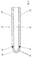
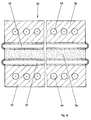
- the shape compensation plate 21 according to the invention which is arranged on the rear side of the carrier plate 42, that is to say on the side of the roller bed facing away from the press belt 8, 9, is composed of two plates arranged parallel to one another and at a certain distance from one another, namely a base plate 22 and a cover plate 23 , as can be seen in Figure 5.
- the base and cover plate 22, 23 consist of metal, for example steel.
- An elastic bellows 24 runs along the edge of the base plate 22 and cover plate 23 and is attached at one end to the base plate 22 and at the other end to the cover plate 23.
- a chamber 25 is formed between the base plate 22 and the cover plate 23, which is hermetically sealed laterally with the elastic bellows 24.
- this chamber 25 which is sealed off from the outside, there is a fluid under pressure as the pressure medium.
- This fluid can be a liquid under pressure, for example oil.
- a gas under pressure into this chamber 25.
- a metallic liquid such as mercury or wood metal, is particularly preferred.
- Wood metal is a low-melting alloy of bismuth, lead, tin and cadmium. If the material web 12 to be pressed is simultaneously heated in the double belt press 1 under the action of pressure, it is also possible to choose an alloy or a metal as the content for the chamber 25 which is molten at the temperature to be applied to which the heat exchange plate 43 is heated for example tin. Due to the hermetic seal by the elastic bellows 24, leakage of the fluid pressure medium from the shape-compensating plate 21 is avoided with certainty.
- the elastic bellows 24, which laterally surrounds the chamber 25, has an approximately semicircular cross section. It is composed of individual, superimposed, rectangular metal foils or sheets 26, the individual layers of the metal foils or sheets 26 being welded into rings. For example, a high tensile spring steel or stainless steel is suitable as material for these sheets.
- This sheet metal ring package is then bent so that it has a semicircular to U-shaped cross section, as can be seen in FIG. 5, and is welded to one another at the edges. This structure gives the laminated core a high degree of elasticity.
- the laminated core is then placed at one end on the base plate 22 and at the other end on the cover plate 23, the laminated core at the corners of the plates 22, 23 being bent in a circle by approximately 90 ° to form a U-quarter curve. Finally, the ends of the laminated core lying against the plates 22, 23 are fastened to the plates 22, 23. This attachment can also be carried out by means of a weld seam.
- the individual metal foils or sheets 26 can also consist of electroformed parts, which are already galvanically deposited in the desired semicircular shape and then welded to one another at the edges 27. As a result, the step of bending the laminated core into a semicircular shape can be omitted.
- the surface pressure exerted by the pressure plate 13 fastened in the press frame 40, 41 acts on the material web 12 via the roller bed and the press belts 8, 9.
- an additional hydraulic pressure acts on the material web 12 from the fluid pressure medium located in the space between the sliding surface seals 20. Due to the applied pressing pressure, reaction forces emanate from the material web 12, which are introduced into the pressure plate 13 via the roller bed and absorbed by the press frame 40, 41 in which the pressure plate 13 is fastened.
- the pressure plate 13 consists of a carrier plate 42 and the shape-compensating plate 21. If bends occur in the roller bed or in the press frame 40, 41, these bends are counteracted by the isobaric pressure behavior of the fluid pressure medium located in the chamber 25 of the shape-adjustment plate 21. This counteraction is supported by the flexibility of the support plate 42.
- the shape compensation plate 21 consists of metallic materials. These are stable even at elevated temperatures. Thus, the double belt press 1 equipped with the shape compensation plate 21 according to the invention can be used reliably even at elevated temperatures.
- a support plate 28 can be arranged in the chamber 25 to support it.
- the support plate 28 is arranged essentially parallel to the base plate 22 and cover plate 23.
- the edge region 29 of the support plate 28 is slightly chamfered.
- the beveled edge region 29 is arranged in the inner curvature of the bellows 24, so that the bellows 24 is supported on the side facing the chamber 25 by the beveled edge region 29.
- Particularly high reaction forces acting on the elastic bellows 24 are then absorbed by the support plate 28.
- This support plate 28 can consist of copper, so that good thermal conductivity is also ensured in the chamber 25. This can be necessary in particular if a metal is selected as the fluid pressure medium in the chamber 25, which becomes molten at the operating temperature of the double belt press 1 or if particularly large amounts of heat between the heat exchange plate 43 and the Press belt 8, 9 to be transferred. If it is desired to increase the elasticity of the chamfered edge region 29 of the support plate 28, incisions 45 can be made in the chamfered edge region 29.
- a further embodiment for the shape-compensating plate 21 can be seen in FIG.
- a bore 30 is made in the upper cover plate 23.
- the fluid pressure medium can be fed into the chamber 25 through this bore 30, so that the pressure in the chamber 25 can advantageously be varied.
- the shape compensation plate 21 only needs to be filled with the fluid pressure medium when it is actually needed. With such an embodiment, a form compensation plate 21 that can be switched on and off can thus be realized.
- the shape compensation plates 21 With the shape compensation plates 21 according to the invention, multi-format double belt presses can also be realized. Since the pressurized press belts 8, 9 are supported in the reaction zone 11 against the material web 12, this extends over the entire width of the reaction zone 11 in conventional double belt presses. In order to be able to use narrower material webs 12 as well, the shape-compensating plate can be used in several transverse, strips extending in the longitudinal direction can be divided, each strip being designed as a separate, self-contained shape-compensating plate. If desired, each strip-shaped shape compensation plate can also be designed so that it can be switched on and off separately.
- Such a strip-shaped arrangement of a plurality of shape compensation plates 31, 32 can be seen in FIG. 7, in which the pressure plate 13 with a roller bed is shown in a top view, the carrier plate 42 being partially omitted in order to show the shape compensation plates 31, 32 located underneath.
- These strip-shaped shape compensation plates 31, 32 are arranged with the desired width and in the desired number in the pressure plate 13. The width of the material web 12 is then selected so that it is just covered by one or more shape-compensating plates 31, 32. This causes deflections at precisely the points in the roller bed compensates where the material web is pressurized, so that ultimately a material web 12 lying within the thickness tolerances is again generated.
- the shape compensation plate according to the invention can be used not only in a continuously operating double belt press, but also in a discontinuously operating deck press 33, as is shown schematically in FIG.
- the pressed material 36 is compressed between two press plates 34 and 35.
- the pressure plates 34, 35 have bores 46 through which a heat transfer medium can be passed so that they can be heated or cooled.
- discrepancies and thickness tolerances in the pressed material 36 and the pressing plates 34, 35, as well as deformations of the press yoke and press table caused by load absorption can cause local pressure differences and cause the pressing plates 34, 35 to warp, which ultimately leads to differences in thickness in the pressing material 36 and thus to rejects leads.
- Such warping of the pressure plates 34, 35 is avoided according to the invention in that the shape compensation plate 37 according to the invention is fastened to the pressure plates 34, 35 on the side facing the material 36 to be pressed.
- a carrier plate can be dispensed with, that is to say the shape-compensating plate 37 can rest directly on the material 36 to be pressed.
- the shape compensation plate 37 is designed in accordance with the above exemplary embodiments and absorbs local pressure differences from the pressed material 36, as a result of which warping or warping of the pressed plates 34, 35 is avoided, so that a pressed material 36 lying within the desired thickness tolerances is produced.
- the shape compensation plate 37 according to the invention can be used not only in single-day presses, but also in multi-day presses. This is done in the same way as for the single-day presses, that is, they are arranged between the material to be pressed and the press plate.
- an attachment of the shape compensation plate 37 to the pressure plates 34, 35 is not absolutely necessary, it is sufficient if the shape compensation plates 37 between the pressure plate 34, 35 and the material to be pressed 36 into the Press 33 can be inserted.
- the shape-compensating plates 37 according to the invention in the case of single- or multi-day presses, the previously customary press pads, which were destroyed after a few press cycles at the latest and therefore had to be discarded, can be replaced by the permanent shape-compensating plate 37.
Landscapes
- Engineering & Computer Science (AREA)
- Mechanical Engineering (AREA)
- Life Sciences & Earth Sciences (AREA)
- Manufacturing & Machinery (AREA)
- Wood Science & Technology (AREA)
- Forests & Forestry (AREA)
- Press Drives And Press Lines (AREA)
- Veneer Processing And Manufacture Of Plywood (AREA)
Applications Claiming Priority (2)
| Application Number | Priority Date | Filing Date | Title |
|---|---|---|---|
| DE4128024 | 1991-08-23 | ||
| DE4128024A DE4128024A1 (de) | 1991-08-23 | 1991-08-23 | Kontinuierlich arbeitende doppelbandpresse |
Publications (3)
| Publication Number | Publication Date |
|---|---|
| EP0529214A2 true EP0529214A2 (fr) | 1993-03-03 |
| EP0529214A3 EP0529214A3 (en) | 1993-06-02 |
| EP0529214B1 EP0529214B1 (fr) | 1996-04-24 |
Family
ID=6438977
Family Applications (1)
| Application Number | Title | Priority Date | Filing Date |
|---|---|---|---|
| EP92109516A Expired - Lifetime EP0529214B1 (fr) | 1991-08-23 | 1992-06-05 | Presse à doubles bandes |
Country Status (5)
| Country | Link |
|---|---|
| US (1) | US5303644A (fr) |
| EP (1) | EP0529214B1 (fr) |
| JP (1) | JPH05200591A (fr) |
| DE (1) | DE4128024A1 (fr) |
| RU (1) | RU2085391C1 (fr) |
Cited By (5)
| Publication number | Priority date | Publication date | Assignee | Title |
|---|---|---|---|---|
| WO2011073331A1 (fr) | 2009-12-17 | 2011-06-23 | Dsm Ip Assets B.V. | Procédé de fabrication de feuille de matériau multicouche, feuille de matériau multicouche et son utilisation |
| WO2014052998A1 (fr) * | 2012-10-05 | 2014-04-10 | Berndorf Band Gmbh | Presse a double bande |
| US8815134B2 (en) | 2008-06-19 | 2014-08-26 | Teijin Aramid B.V. | Process for manufacturing polyolefin films |
| AT516907A1 (de) * | 2015-07-28 | 2016-09-15 | Berndorf Band Gmbh | Doppelbandpresse mit begrenztem Ausgleich einer Pressspaltbreite |
| ITUB20160504A1 (it) * | 2016-01-15 | 2017-07-15 | System Spa | Compensatore di formato per un dispositivo di pressatura |
Families Citing this family (17)
| Publication number | Priority date | Publication date | Assignee | Title |
|---|---|---|---|---|
| EP0710541B1 (fr) * | 1994-10-12 | 1998-05-27 | Firma Theodor Hymmen | Dispositif de fabrication en continu de produits multicouches plats |
| IT1306962B1 (it) * | 1999-01-18 | 2001-10-11 | Pierluigi Bolzoni | Metodo ed impianto per il trattamento termico di fogli di legno |
| DE19937694B4 (de) * | 1999-08-10 | 2004-11-25 | Siempelkamp Maschinen- Und Anlagenbau Gmbh & Co. Kg | Plattenpresse, insbesondere Einetagenpresse |
| US6908295B2 (en) * | 2000-06-16 | 2005-06-21 | Avery Dennison Corporation | Process and apparatus for embossing precise microstructures and embossing tool for making same |
| US6481188B1 (en) | 2000-06-30 | 2002-11-19 | Owens Corning Fiberglas Technology, Inc. | Apparatus and method for sealing an article |
| DE10248387B4 (de) * | 2002-10-17 | 2005-03-17 | Giesecke & Devrient Gmbh | Doppelbandpresse |
| DE20306758U1 (de) * | 2003-05-02 | 2004-06-09 | Kronospan Technical Company Ltd., Engomi | Presse mit Korrektur eines Pressbandverlaufs |
| US20100294644A1 (en) * | 2009-05-20 | 2010-11-25 | Zanaqua Technologies | Heat exchanger |
| CN102303349B (zh) * | 2011-07-08 | 2013-11-27 | 中国林业科学研究院林业新技术研究所 | 一种模块化结构的连续压机 |
| CN102241045B (zh) * | 2011-07-08 | 2013-11-06 | 中国林业科学研究院林业新技术研究所 | 一种辊盘式连续压机 |
| CN102259373B (zh) * | 2011-07-08 | 2013-11-06 | 中国林业科学研究院林业新技术研究所 | 一种用于加工板材的辊盘式连续压机 |
| DE102015116267B4 (de) * | 2015-09-25 | 2025-10-30 | Bundesdruckerei Gmbh | Laminierwerkzeug und Laminiervorrichtung sowie Verfahren zum Laminieren von mehreren in einem Stapel angeordneten Schichten |
| ITUA20161363A1 (it) * | 2016-03-04 | 2017-09-04 | System Spa | Dispositivo di pressatura |
| JP6334795B1 (ja) * | 2017-09-05 | 2018-05-30 | プロセスシステム株式会社 | ダブルベルトプレス装置および誘導加熱プレスモジュール |
| US11054193B2 (en) | 2018-05-30 | 2021-07-06 | Amazon Technologies, Inc. | Vehicle with vibration isolated electronics |
| US10912224B2 (en) * | 2018-05-30 | 2021-02-02 | Amazon Technologies, Inc. | Thermally conductive vibration isolating connector |
| DE102018118212B3 (de) | 2018-07-27 | 2020-01-30 | Held Technologie Gmbh | Gleitflächendichtung für eine kontinuierlich arbeitende Doppelbandpresse und Doppelbandpresse |
Family Cites Families (27)
| Publication number | Priority date | Publication date | Assignee | Title |
|---|---|---|---|---|
| CH25013A (de) * | 1901-09-12 | 1903-03-15 | Hansen Ellehammer Jacob Christ | Apparat zur Herstellung von Cigaretten |
| US2142932A (en) * | 1935-03-11 | 1939-01-03 | Beard Veneer Products Inc | Plywood press |
| CH250131A (de) * | 1945-04-14 | 1947-08-15 | Ley Emil | Heizbare Pressvorrichtung. |
| US2627628A (en) * | 1949-08-25 | 1953-02-10 | Rca Corp | Molding cushion |
| CH327433A (de) * | 1954-01-15 | 1958-01-31 | Voelskow Peter | Einrichtung zum kontinuierlich fortschreitenden Pressen |
| BE639082A (fr) * | 1962-10-24 | 1900-01-01 | ||
| DE1241405B (de) * | 1964-09-18 | 1967-06-01 | Kannegiesser & Co Maschinenfab | Formkoerperbuegelpresse zum Heissverkleben von Bekleidungsstueckteilen od. dgl. |
| CH442730A (de) * | 1965-09-14 | 1967-08-31 | Bell Ag Maschf | Presskissen zum gleichmässigen Pressen von plattenförmigen Körpern |
| BE724136A (fr) * | 1967-11-23 | 1969-05-19 | ||
| GB1270110A (en) * | 1968-08-05 | 1972-04-12 | Ici Ltd | Improvements in or relating to pressing processes |
| US3619310A (en) * | 1969-11-06 | 1971-11-09 | Ici Ltd | Method of making liquid-filled pressure-distributing pads used in presses |
| DE1963806C3 (de) * | 1969-12-19 | 1974-04-11 | Wsesojusnij Nautschno-Issledowatel' Skij I Konstruktorskij Institut Derewoobrabatywajuszego Maschinostrojenija, Moskau | Kontinuierlich arbeitende Preßeinrichtung zur Verkleidung der Oberflächen von flachen Werkstücken durch Verleimung |
| US3817803A (en) * | 1972-06-19 | 1974-06-18 | Fmc Corp | Method of making a cellular cushioning structure |
| US4190484A (en) * | 1975-10-20 | 1980-02-26 | Rembert Duvelius | Press for producing shaped articles |
| JPS5310673A (en) * | 1976-07-16 | 1978-01-31 | Sounosuke Nagato | Improvement related to continuous molding and vulcanizing method for high molecular long material |
| DE2724056C3 (de) * | 1977-05-27 | 1979-11-22 | Fa. Carl Freudenberg, 6940 Weinheim | Ausgleichsplatte für eine Vulkanisierpresse oder ähnliche Pressen |
| US4247963A (en) * | 1979-04-10 | 1981-02-03 | Lakshmi Reddi | Liquid support construction |
| DE2922151A1 (de) * | 1979-05-31 | 1980-12-11 | Sandvik Conveyor Gmbh | Doppelbandpresse |
| DE2937410A1 (de) * | 1979-09-15 | 1981-04-02 | Into Solymar Benalmadena Costa Malaga Kerttula | Kontinuierlich arbeitende plattenpresse |
| DE3123291C2 (de) * | 1981-06-12 | 1993-04-15 | Held, Kurt, 7218 Trossingen | Rollenbett an einer kontinuierlich arbeitenden Presse |
| DE3348457C2 (de) * | 1982-02-27 | 1995-12-07 | Held Kurt | Vorrichtung zur Stützung der Preßbänder an wälzkörpergestützten Doppelbandpressen |
| EP0087651B2 (fr) * | 1982-02-27 | 1994-06-08 | Kurt Held | Dispositif pour soutenir les bandes de pressage par des rouleaux dans des presses à double bande |
| JPS59191600A (ja) * | 1983-04-15 | 1984-10-30 | Hitachi Ltd | ホツトプレス |
| DE3431520A1 (de) * | 1984-08-28 | 1986-07-10 | G. Siempelkamp Gmbh & Co, 4150 Krefeld | Kontinuierlich arbeitende beschichtungspresse |
| DE3534478C2 (de) * | 1985-09-27 | 1995-01-26 | Held Kurt | Doppelbandpresse zum kontinuierlichen Verpressen von Werkstoffbahnen bei erhöhten Temperaturen |
| DE3616619C2 (de) * | 1986-05-16 | 1994-11-17 | Held Kurt | Dichtungsanordnung an einer Doppelbandpresse und Verfahren zur Herstellung der zugehörigen Dichtungskörper |
| JPH0832378B2 (ja) * | 1988-11-18 | 1996-03-29 | 株式会社名機製作所 | 多段プレス装置 |
-
1991
- 1991-08-23 DE DE4128024A patent/DE4128024A1/de not_active Withdrawn
-
1992
- 1992-06-05 EP EP92109516A patent/EP0529214B1/fr not_active Expired - Lifetime
- 1992-08-17 RU SU925052515A patent/RU2085391C1/ru active
- 1992-08-24 JP JP4223964A patent/JPH05200591A/ja active Pending
- 1992-08-25 US US07/935,092 patent/US5303644A/en not_active Expired - Fee Related
Cited By (12)
| Publication number | Priority date | Publication date | Assignee | Title |
|---|---|---|---|---|
| US8815134B2 (en) | 2008-06-19 | 2014-08-26 | Teijin Aramid B.V. | Process for manufacturing polyolefin films |
| WO2011073331A1 (fr) | 2009-12-17 | 2011-06-23 | Dsm Ip Assets B.V. | Procédé de fabrication de feuille de matériau multicouche, feuille de matériau multicouche et son utilisation |
| US10071536B2 (en) | 2009-12-17 | 2018-09-11 | Dsm Ip Assets B.V. | Process for the manufacture of a multilayer material sheet, multilayer material sheet and use hereof |
| US10315380B2 (en) | 2009-12-17 | 2019-06-11 | Dsm Ip Assets B.V. | Process for the manufacture of a multilayer material sheet, multilayer material sheet and use hereof |
| WO2014052998A1 (fr) * | 2012-10-05 | 2014-04-10 | Berndorf Band Gmbh | Presse a double bande |
| AT520169A5 (de) * | 2012-10-05 | 2019-01-15 | Berndorf Band Gmbh | Doppelbandpresse |
| AT520169B1 (de) * | 2012-10-05 | 2019-05-15 | Berndorf Band Gmbh | Doppelbandpresse |
| AT516907A1 (de) * | 2015-07-28 | 2016-09-15 | Berndorf Band Gmbh | Doppelbandpresse mit begrenztem Ausgleich einer Pressspaltbreite |
| ITUB20160504A1 (it) * | 2016-01-15 | 2017-07-15 | System Spa | Compensatore di formato per un dispositivo di pressatura |
| WO2017122124A1 (fr) * | 2016-01-15 | 2017-07-20 | System S.P.A. | Compensateur de taille pour un dispositif de pression |
| CN108472906A (zh) * | 2016-01-15 | 2018-08-31 | 系统股份公司 | 用于压制装置的尺寸补偿器 |
| US10675778B2 (en) | 2016-01-15 | 2020-06-09 | System Ceramics S.P.A. | Size compensator for a pressing device |
Also Published As
| Publication number | Publication date |
|---|---|
| DE4128024A1 (de) | 1993-02-25 |
| EP0529214B1 (fr) | 1996-04-24 |
| RU2085391C1 (ru) | 1997-07-27 |
| JPH05200591A (ja) | 1993-08-10 |
| EP0529214A3 (en) | 1993-06-02 |
| US5303644A (en) | 1994-04-19 |
Similar Documents
| Publication | Publication Date | Title |
|---|---|---|
| EP0529214B1 (fr) | Presse à doubles bandes | |
| EP0292738B1 (fr) | Presse à double bande à parties pouvant être chauffées ou refroidies et procédé pour leur fabrication | |
| EP0126845B1 (fr) | Presse à fonctionnement continu avec des bandes de pressage à couches multiples | |
| DE69027638T2 (de) | Anordnung für die Herstellung magnetischer Karten | |
| DE2737629C2 (de) | Kontinuierlich arbeitende Doppelbandpresse | |
| EP0087651B1 (fr) | Dispositif pour soutenir les bandes de pressage par des rouleaux dans des presses à double bande | |
| DD296883A5 (de) | Pressanlage zum kontinuierlichen pressen von pressgutbahnen | |
| DE3616619C2 (de) | Dichtungsanordnung an einer Doppelbandpresse und Verfahren zur Herstellung der zugehörigen Dichtungskörper | |
| DE3936924A1 (de) | Verfahren und vorrichtung zur beheizung einer kontinuierlich arbeitenden heizplattenpresse | |
| DE3436158C2 (fr) | ||
| DE3445636C2 (fr) | ||
| EP0140117B1 (fr) | Presse à travailler continuellement pour presser un lé de matière en mouvement | |
| DE3347877C2 (de) | Seitenabdichtung des Preßraumes einer Doppelbandpresse | |
| EP0163864B1 (fr) | Procédé et dispositif pour comprimer d'une matière continue des bandes de matériaux | |
| DE102009023577A1 (de) | Presse, insbesondere kontinuierlich arbeitende Presse zur Herstellung von Werkstoffplatten | |
| DE3123291C2 (de) | Rollenbett an einer kontinuierlich arbeitenden Presse | |
| DE2909277C2 (de) | Walze für die Druckbehandlung von Warenbahnen | |
| EP0562280B1 (fr) | Corp d'obturation latérale pour une presse continue à doubles bandes | |
| DE4208263A1 (de) | Kontinuierliche presse fuer das pressen einer pressgutmatte im zuge der herstellung von spanplatten, faserplatten u. dgl. | |
| EP0710541A1 (fr) | Dispositif de fabrication en continu de produits multicouches plats | |
| DE3304754C2 (de) | Verfahren und Vorrichtung zur Stützung der Pressbänder an wälzkörpergestützten Doppelbandpressen | |
| DE102005055855B4 (de) | Druckzone einer Doppelbandpresse | |
| DE3145085A1 (de) | Doppelbandpresse | |
| DE2928530A1 (de) | Kontinuierlich arbeitende anlage fuer das pressen von pressgut im zuge der herstellung von spanplatten, faserplatten u.dgl. | |
| DE2736099C2 (de) | Kontinuierlich arbeitende Presse |
Legal Events
| Date | Code | Title | Description |
|---|---|---|---|
| PUAI | Public reference made under article 153(3) epc to a published international application that has entered the european phase |
Free format text: ORIGINAL CODE: 0009012 |
|
| 17P | Request for examination filed |
Effective date: 19920605 |
|
| AK | Designated contracting states |
Kind code of ref document: A2 Designated state(s): FR GB IT SE |
|
| PUAL | Search report despatched |
Free format text: ORIGINAL CODE: 0009013 |
|
| AK | Designated contracting states |
Kind code of ref document: A3 Designated state(s): FR GB IT SE |
|
| 17Q | First examination report despatched |
Effective date: 19940712 |
|
| GRAA | (expected) grant |
Free format text: ORIGINAL CODE: 0009210 |
|
| AK | Designated contracting states |
Kind code of ref document: B1 Designated state(s): FR GB IT SE |
|
| PG25 | Lapsed in a contracting state [announced via postgrant information from national office to epo] |
Ref country code: IT Free format text: LAPSE BECAUSE OF FAILURE TO SUBMIT A TRANSLATION OF THE DESCRIPTION OR TO PAY THE FEE WITHIN THE PRESCRIBED TIME-LIMIT;WARNING: LAPSES OF ITALIAN PATENTS WITH EFFECTIVE DATE BEFORE 2007 MAY HAVE OCCURRED AT ANY TIME BEFORE 2007. THE CORRECT EFFECTIVE DATE MAY BE DIFFERENT FROM THE ONE RECORDED. Effective date: 19960424 Ref country code: FR Effective date: 19960424 Ref country code: GB Effective date: 19960424 |
|
| EN | Fr: translation not filed | ||
| GBV | Gb: ep patent (uk) treated as always having been void in accordance with gb section 77(7)/1977 [no translation filed] |
Effective date: 19960424 |
|
| PLBE | No opposition filed within time limit |
Free format text: ORIGINAL CODE: 0009261 |
|
| STAA | Information on the status of an ep patent application or granted ep patent |
Free format text: STATUS: NO OPPOSITION FILED WITHIN TIME LIMIT |
|
| 26N | No opposition filed | ||
| PGFP | Annual fee paid to national office [announced via postgrant information from national office to epo] |
Ref country code: SE Payment date: 19970807 Year of fee payment: 6 |
|
| PG25 | Lapsed in a contracting state [announced via postgrant information from national office to epo] |
Ref country code: SE Free format text: LAPSE BECAUSE OF NON-PAYMENT OF DUE FEES Effective date: 19980606 |
|
| EUG | Se: european patent has lapsed |
Ref document number: 92109516.2 |