EP0052782B1 - Système de suspension pour véhicules - Google Patents
Système de suspension pour véhicules Download PDFInfo
- Publication number
- EP0052782B1 EP0052782B1 EP81108957A EP81108957A EP0052782B1 EP 0052782 B1 EP0052782 B1 EP 0052782B1 EP 81108957 A EP81108957 A EP 81108957A EP 81108957 A EP81108957 A EP 81108957A EP 0052782 B1 EP0052782 B1 EP 0052782B1
- Authority
- EP
- European Patent Office
- Prior art keywords
- spring
- piston
- suspension according
- displacer
- springs
- Prior art date
- Legal status (The legal status is an assumption and is not a legal conclusion. Google has not performed a legal analysis and makes no representation as to the accuracy of the status listed.)
- Expired
Links
Images


Classifications
-
- B—PERFORMING OPERATIONS; TRANSPORTING
- B60—VEHICLES IN GENERAL
- B60G—VEHICLE SUSPENSION ARRANGEMENTS
- B60G15/00—Resilient suspensions characterised by arrangement, location or type of combined spring and vibration damper, e.g. telescopic type
- B60G15/08—Resilient suspensions characterised by arrangement, location or type of combined spring and vibration damper, e.g. telescopic type having fluid spring
- B60G15/12—Resilient suspensions characterised by arrangement, location or type of combined spring and vibration damper, e.g. telescopic type having fluid spring and fluid damper
-
- B—PERFORMING OPERATIONS; TRANSPORTING
- B60—VEHICLES IN GENERAL
- B60G—VEHICLE SUSPENSION ARRANGEMENTS
- B60G11/00—Resilient suspensions characterised by arrangement, location or kind of springs
- B60G11/26—Resilient suspensions characterised by arrangement, location or kind of springs having fluid springs only, e.g. hydropneumatic springs
- B60G11/30—Resilient suspensions characterised by arrangement, location or kind of springs having fluid springs only, e.g. hydropneumatic springs having pressure fluid accumulator therefor, e.g. accumulator arranged in vehicle frame
-
- B—PERFORMING OPERATIONS; TRANSPORTING
- B60—VEHICLES IN GENERAL
- B60G—VEHICLE SUSPENSION ARRANGEMENTS
- B60G15/00—Resilient suspensions characterised by arrangement, location or type of combined spring and vibration damper, e.g. telescopic type
-
- B—PERFORMING OPERATIONS; TRANSPORTING
- B60—VEHICLES IN GENERAL
- B60G—VEHICLE SUSPENSION ARRANGEMENTS
- B60G17/00—Resilient suspensions having means for adjusting the spring or vibration-damper characteristics, for regulating the distance between a supporting surface and a sprung part of vehicle or for locking suspension during use to meet varying vehicular or surface conditions, e.g. due to speed or load
- B60G17/02—Spring characteristics, e.g. mechanical springs and mechanical adjusting means
- B60G17/04—Spring characteristics, e.g. mechanical springs and mechanical adjusting means fluid spring characteristics
- B60G17/0416—Spring characteristics, e.g. mechanical springs and mechanical adjusting means fluid spring characteristics regulated by varying the resiliency of hydropneumatic suspensions
- B60G17/0424—Spring characteristics, e.g. mechanical springs and mechanical adjusting means fluid spring characteristics regulated by varying the resiliency of hydropneumatic suspensions by varying the air pressure of the accumulator
-
- B—PERFORMING OPERATIONS; TRANSPORTING
- B60—VEHICLES IN GENERAL
- B60G—VEHICLE SUSPENSION ARRANGEMENTS
- B60G2204/00—Indexing codes related to suspensions per se or to auxiliary parts
- B60G2204/80—Interactive suspensions; arrangement affecting more than one suspension unit
-
- B—PERFORMING OPERATIONS; TRANSPORTING
- B60—VEHICLES IN GENERAL
- B60G—VEHICLE SUSPENSION ARRANGEMENTS
- B60G2204/00—Indexing codes related to suspensions per se or to auxiliary parts
- B60G2204/80—Interactive suspensions; arrangement affecting more than one suspension unit
- B60G2204/82—Interactive suspensions; arrangement affecting more than one suspension unit left and right unit on same axle
-
- B—PERFORMING OPERATIONS; TRANSPORTING
- B60—VEHICLES IN GENERAL
- B60G—VEHICLE SUSPENSION ARRANGEMENTS
- B60G2204/00—Indexing codes related to suspensions per se or to auxiliary parts
- B60G2204/80—Interactive suspensions; arrangement affecting more than one suspension unit
- B60G2204/83—Type of interconnection
- B60G2204/8304—Type of interconnection using a fluid
-
- B—PERFORMING OPERATIONS; TRANSPORTING
- B60—VEHICLES IN GENERAL
- B60G—VEHICLE SUSPENSION ARRANGEMENTS
- B60G2500/00—Indexing codes relating to the regulated action or device
- B60G2500/20—Spring action or springs
- B60G2500/206—Variable pressure accumulators for hydropneumatic suspensions
- B60G2500/2062—Variable pressure accumulators for hydropneumatic suspensions by varying the air-pressure of the accumulator
-
- B—PERFORMING OPERATIONS; TRANSPORTING
- B60—VEHICLES IN GENERAL
- B60G—VEHICLE SUSPENSION ARRANGEMENTS
- B60G2500/00—Indexing codes relating to the regulated action or device
- B60G2500/20—Spring action or springs
- B60G2500/206—Variable pressure accumulators for hydropneumatic suspensions
- B60G2500/2064—Variable pressure accumulators for hydropneumatic suspensions by varying the number of accumulators connected in parallel to the hydraulic cylinder
Definitions
- the invention relates to a suspension system for vehicles, with a displacer which can be actuated by the relative movements between the wheel and the vehicle body and whose working space is connected to at least two springs which can be acted upon by a fluid with the interposition of at least one throttle.
- the invention has for its object to provide a suspension system for vehicles of the type mentioned, with which the damping increases in a particularly simple manner with increasing load on the system.
- the possibility is also to be opened here of changing the damping as a function of frequency by means of further configurations.
- the first spring can be comparatively softer than the second, which is why, at this load, the proportion of the fluid pushed into this softer spring is greater than the proportion of the fluid displaced towards the second spring.
- the throttle upstream of the second spring will therefore only produce less damping force because of the reduced volume fraction flowing through it. If the first spring mentioned (for example a hydropneumatic spring with a constant gas mass) already has a significantly higher spring rate than the second spring mentioned under higher loads, then a much higher proportion of the displaced volume flows to the now "softer" second spring during this loading , which is why the throttle upstream of the second spring generates significantly more damping force.
- the throttle therefore exerts a higher damping force when the vehicle is heavily loaded than in the case of a low load, the damping force transitions being infinitely variable.
- the suspension comprises a damper type displacer 1, in which the piston rod 2 serves as the actual displacer.
- the throttle D 3 is provided for the basic damping.
- the throttle D 3 can consist of spring-loaded valves for the wheel damping in conjunction with a constant opening which is dimensioned so large that sufficient body damping is ensured when the vehicle is empty.
- the springs F1 and F2 are arranged spatially next to one another and connected in series in the spring action;
- the oil volume displaced by the piston rod 2 during compression is divided into two volume flows, one of which is fed to the spring F 1 and the other to the spring F 2.
- the spring F 2 is preceded by a throttle D 2, which takes over the additional body damping at higher loads.
- the two springs F 1 and F 2 are hydropneumatic springs, the spring F 1 being a diaphragm accumulator and the spring F 2 being a piston accumulator. Both springs have constant gas masses.
- the piston 4 of the spring F 2 is connected to a mechanical additional spring 5, which is arranged as a compression spring in the gas space of the piston accumulator. With the additional spring 5, the characteristic of the spring F 2 is "linearized", as a comparison of FIGS. 1 a and 1 b should show.
- Fig. 1 a the typical characteristic curve of a gas spring is plotted, which with a low load (p stat . Empty) still has a comparatively flat curve, but which quickly becomes very steep with increasing load ( Pstat . Bel .).
- the displacer is a pure plunger piston 6.
- the basic damping is taken over by the throttles D 1 and D 2 upstream of the springs F 1 and F 2 '.
- the throttle D 2 has the one of these two throttles greater flow resistance and determines the additional body damping:
- the springs F 1 and F 2 ' for realizing the inventive concept are realized in this embodiment in that the spring F 1 is designed as a spring with a constant gas weight and the spring F 2' as a spring with a variable gas weight.
- the gas space of the spring F 2 ' is expediently connected to a level regulator, as is indicated in FIG. 2 by the line 7.
- FIG. 2 a shows the characteristic curve of the spring F 1
- FIG. 2 b shows the lower curve would be the curve of the spring F 2 'if it were not level-controlled.
- the upper curve shows the characteristic of the spring F 2 'at higher loads.
- the level regulation namely supplies the spring F 2 'with the amount of gas which has been swallowed by the compression of both springs F 1 and F 2'. This makes F 2 'even softer than, for example, a single spring with a constant gas volume (but regulated gas mass), to which only the gas volume compressed by itself is supplied.
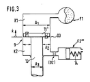
- FIG 3 shows an embodiment in which the springs F 1 and F 2 "'are opposite one another (as if mechanically connected in parallel).
- the spring F 1 is connected to the chamber K 1 and the spring F 2"' to the chamber K 2 a two-chamber piston displacer.
- the suspension shown in Fig. 3 has a dependency of the damping force on the frequency, with a dependency on the load.
- the suspension is fully load-bearing, which is why the cross section of the piston rod 13 is selected to be relatively large.
- the hydropneumatic spring F 1 is connected to the piston rod-free side of the piston displacer 9.
- a piston accumulator with a purely mechanical spring 14 is connected to the chamber K 2, that is to say the piston rod side of the displacer 9.
- the spring F 2 "'has a purely linear identifier, since the chamber in which the spring 14 is arranged is vented to the atmosphere.
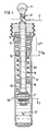
- FIG. 4 shows a somewhat more practical possibility of realizing the suspension principle shown more schematically in FIG. 3.
- the mechanical spring 14 is integrated in the piston displacer 9 'and is supported on the one hand on its cylinder cover 15 and on the other hand on a separating piston 16 delimiting the piston rod-side working space.
- This working space corresponds to the chamber K 2 as shown in FIG. 3.
- Below the piston 11 ' is the chamber K 1, which ver ver via the hollow piston rod 13' with the hydropneumatic spring F 1 is bound, the additional chokes D 1 are connected upstream.
- the connection 17 for level regulation is also indicated.
- tension stop spring 18 is provided, which can also be designed progressively.
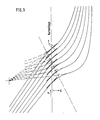
- FIG. 5 shows a family of characteristic curves as is possible with the suspension and damping according to FIG. 4 in conjunction with level regulation.
- a spring made of polyurethane or a similar rubber-elastic material supported on the stop ring 19 could also be used.
- the damping force profile is also influenced by the tension stop spring 18 as a function of the load.
- the damping force of the throttle D3 drops to zero, since the piston 11 'and the separating piston 16 move at the same speed.
- the sufficient basic damping then causes the throttle D1 (Fig. 4). It is also possible to completely omit the tension stop spring 18, the stop ring 19 (with a corresponding kink in the overall spring characteristic) striking against the separating piston 16 from a certain displacement path x and then taking it along.
- the additional load-dependent damping effect (load-dependent change in the displacer speed x) is superimposed on the effect of the system according to FIG. 3 (load-dependent increase in the displacer area from A 2 to A 1 ), the load dependency of the damping force is thus further increased.
- the tension stop spring 18 causes the action of the spring F 2"'(both act on the separating piston 16) the hydraulic system is corrected as if F 2 "'had a load-dependent (degressive) characteristic curve and was very hard in the empty state, but normal in the event of a load.
- the vehicle is empty while in the state of greater stress applies: respectively
- the different volume flow allocation to the at least two springs of the overall suspension system can therefore be achieved not only by different spring rate profiles - for example one with a progressive spring and the other with a linear identifier - but also by different switching of the springs, for example by parallel connection in the idle state and series connection under load.
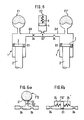
- a spring F 1 or F 1 ′ of a wheel or wheel pair of a vehicle axle can also be connected to a second spring F 2 common to these two.
- the common spring F 2 is a piston accumulator, which is in the gas space by a Spring 5 was reinforced and thus linearized.
- the additional load-dependent structural damping can be provided by a throttle D 2 'provided at the input of the common spring F 2.
- a throttle D 4 it is also possible to install a throttle D 4 in each individual line 20 leading from the displacers 1 to the common second spring F 2.
- the additional body damping only comes into effect when the wheels move in the same direction, while when the wheels move in opposite directions, the oil is pushed unthrottled from one side to the other.
- this common spring F 12 can also be a diaphragm accumulator.
- the membrane 21 can rest on the feed opening 22 of the membrane accumulator at low working pressures.
- the spring F 12 only comes into operation when its filling pressure is exceeded by the system pressure. This embodiment therefore has the disadvantage that the spring and damping force curve change discontinuously.
- the piston 23 is supported by two mechanical springs 24 on the bottoms of the unit.
- the fluid chambers formed on both sides of the piston 23 are each assigned to a displacer 1 of one of the two wheels of an axle in an analogous manner to the exemplary embodiment according to FIG. 6.
- the variant according to FIG. 6 b does not allow any additional stroke damping, but only additional roll damping in connection with a roll spring rate that is softer than the stroke spring rate, since the piston 23 is only moved out of its central position against the force of the springs 24 when the wheels move against each other.
Landscapes
- Engineering & Computer Science (AREA)
- Mechanical Engineering (AREA)
- Vehicle Body Suspensions (AREA)
Claims (24)
Applications Claiming Priority (2)
| Application Number | Priority Date | Filing Date | Title |
|---|---|---|---|
| DE3044287 | 1980-11-25 | ||
| DE3044287 | 1980-11-25 |
Publications (3)
| Publication Number | Publication Date |
|---|---|
| EP0052782A2 EP0052782A2 (fr) | 1982-06-02 |
| EP0052782A3 EP0052782A3 (en) | 1982-11-24 |
| EP0052782B1 true EP0052782B1 (fr) | 1986-05-28 |
Family
ID=6117483
Family Applications (1)
| Application Number | Title | Priority Date | Filing Date |
|---|---|---|---|
| EP81108957A Expired EP0052782B1 (fr) | 1980-11-25 | 1981-10-27 | Système de suspension pour véhicules |
Country Status (3)
| Country | Link |
|---|---|
| US (1) | US4478431A (fr) |
| EP (1) | EP0052782B1 (fr) |
| DE (1) | DE3174727D1 (fr) |
Families Citing this family (54)
| Publication number | Priority date | Publication date | Assignee | Title |
|---|---|---|---|---|
| DE3414257C2 (de) * | 1984-04-14 | 1993-12-02 | Bosch Gmbh Robert | Federelement mit veränderbarer Härte für Fahrzeuge |
| DE3526156A1 (de) * | 1985-07-22 | 1987-01-29 | Kaspar Lochner | Lastabhaengiges feder-daempfer-aggregat |
| DE3537325A1 (de) * | 1985-10-19 | 1987-04-23 | Messerschmitt Boelkow Blohm | Aktives federungselement, insbesondere fuer schienengebundene hochgeschwindigkeitsfahrzeuge |
| JPS63301115A (ja) * | 1987-05-29 | 1988-12-08 | Nissan Motor Co Ltd | 油圧式サスペンション |
| DE3724271A1 (de) * | 1987-07-22 | 1989-02-02 | Bosch Gmbh Robert | Daempfungsvorrichtung |
| US4798398A (en) * | 1987-08-12 | 1989-01-17 | Unit Rig & Equipment Co. | Dual rate equalizer suspension |
| DE3824611A1 (de) * | 1988-07-20 | 1990-01-25 | Bayerische Motoren Werke Ag | Feder-daempfer-system fuer fahrzeuge |
| US5016911A (en) * | 1988-07-29 | 1991-05-21 | Mazda Motor Corporation | Automotive suspension system |
| JP2584318B2 (ja) * | 1989-07-14 | 1997-02-26 | マツダ株式会社 | 車両のサスペンション装置 |
| EP0493490A4 (en) * | 1989-09-29 | 1993-06-09 | Towerhill Holdings Pty Ltd. | Interconnected fluid suspension for vehicles |
| ES2060888T3 (es) * | 1989-10-28 | 1994-12-01 | Hemscheidt Fahrwerktech Gmbh | Sistema de suspension hidroneumatica. |
| DE59003689D1 (de) * | 1989-11-07 | 1994-01-13 | Daimler Benz Ag | Hydropneumatisches Federungssystem. |
| US5080392A (en) * | 1990-04-26 | 1992-01-14 | Cb Auto Design Inc. | Suspension unit |
| GB9015337D0 (en) * | 1990-07-12 | 1990-08-29 | Rodney Linval | Spring device |
| US5154442A (en) * | 1990-11-19 | 1992-10-13 | Milliken Douglas L | Self-contained acceleration-responsive adaptive damper |
| DE4102787C2 (de) * | 1991-01-31 | 1998-07-30 | Daimler Benz Ag | Federungssystem, insbesondere für Kraftfahrzeuge |
| DE4226754A1 (de) * | 1991-09-21 | 1993-03-25 | Bosch Gmbh Robert | Aufhaengungssystem fuer fahrzeuge |
| DE4234217C2 (de) * | 1992-10-10 | 1996-07-11 | Hemscheidt Fahrwerktech Gmbh | Hydropneumatisches Federungssystem |
| US5624105A (en) * | 1992-10-10 | 1997-04-29 | Hemscheidt Fahrwerktechnik Gmbh & Co. | Hydropneumatic suspension system |
| SE505594C2 (sv) * | 1992-10-15 | 1997-09-22 | Oehlins Racing Ab | Anordning vid stötdämpararrangemang |
| US5322321A (en) * | 1992-12-28 | 1994-06-21 | Ford Motor Company | Vehicle active suspension system |
| US5374077A (en) * | 1993-01-11 | 1994-12-20 | Paccar Inc. | Pneumatically damped vehicle suspension system |
| IT1271171B (it) * | 1993-04-08 | 1997-05-27 | Fichtel & Sachs Ag | Ammortizzatore operante selettivamente nella frequenza |
| DE19608617A1 (de) * | 1996-03-06 | 1997-09-11 | Linke Hofmann Busch | Verfahren zur Verbesserung des Fahrkomforts |
| US5957252A (en) * | 1996-08-02 | 1999-09-28 | Berthold; Brian D. | Hydraulic suspension unit |
| GB2347395B (en) * | 1999-03-04 | 2002-07-31 | Rover Group | Vehicle suspension dampers |
| AUPR249901A0 (en) * | 2001-01-10 | 2001-02-01 | Kinetic Pty Limited | Vehicle suspension roll control system |
| EP1231085B1 (fr) * | 2001-02-09 | 2007-04-25 | Technology Investments Limited | Système de suspension hydropneumatique |
| US6450304B1 (en) | 2001-02-12 | 2002-09-17 | Delphi Technologies, Inc. | Piston and rod assembly for air-actuated variable damping |
| US6837344B2 (en) | 2001-02-12 | 2005-01-04 | Delphi Technologies, Inc. | Piston and rod assembly for air-actuated variable damping |
| US20020121416A1 (en) * | 2001-02-19 | 2002-09-05 | Yohei Katayama | Hydraulic cylinder apparatus |
| US20040094929A1 (en) * | 2001-02-23 | 2004-05-20 | Valentino Ribi | Vehicle having interconnected suspensions |
| EP1388442B1 (fr) * | 2002-08-09 | 2006-11-02 | Kerler, Johann, jun. | Suspension et réglage en hauteur pneumatique pour véhicule |
| DE10259532A1 (de) * | 2002-12-19 | 2004-07-01 | Daimlerchrysler Ag | Stützlager eines schwingungsdämpfenden Elements |
| JP4155066B2 (ja) * | 2003-03-12 | 2008-09-24 | トヨタ自動車株式会社 | 車両懸架装置 |
| US20050173849A1 (en) * | 2004-02-10 | 2005-08-11 | Bart Vandewal | Electronically controlled frequency dependent damping |
| DE102004027885A1 (de) * | 2004-05-28 | 2005-12-22 | Dr.Ing.H.C. F. Porsche Ag | Feder-Dämpfer-Einheit für ein Fahrwerk eines Kraftfahrzeuges |
| JP2006076469A (ja) * | 2004-09-10 | 2006-03-23 | Toyota Motor Corp | サスペンション装置 |
| ES2344997T3 (es) * | 2006-07-28 | 2010-09-13 | Marabese Design S.R.L. | Sistema para controlar la compensacion en motocicletas con tres o cuatro ruedas. |
| DE102006045236A1 (de) * | 2006-09-26 | 2008-04-03 | Zf Friedrichshafen Ag | Geräuschoptimierter Schwingungsdämpfer |
| FR2907049B1 (fr) * | 2006-10-11 | 2009-01-30 | Peugeot Citroen Automobiles Sa | Dispositif de suspension amortie d'un vehicule |
| WO2009158329A2 (fr) | 2008-06-27 | 2009-12-30 | Absolute Electronic Solutions, Inc. | Véhicule tracteur de semi-remorque à plateau réglable |
| EP2527171A1 (fr) * | 2008-11-18 | 2012-11-28 | Hemscheidt Fahrwerktechnik GmbH & Co. KG | Système d'amortissement pour véhicules |
| ITTO20090139A1 (it) * | 2009-02-26 | 2010-08-27 | Cnh Italia Spa | Veicolo agricolo |
| US8807542B2 (en) * | 2009-06-05 | 2014-08-19 | Fox Factory, Inc. | Apparatus and methods for a vehicle shock absorber |
| DE102011084089A1 (de) * | 2011-10-06 | 2013-04-11 | Bayerische Motoren Werke Aktiengesellschaft | Fahrzeug-Radaufhängung mit einem hydraulischen Schwingungs-Dämpfer |
| ITMI20121683A1 (it) * | 2012-10-08 | 2014-04-09 | Gabriele Bellani | Sospensione per veicolo a ruote |
| US9670979B1 (en) | 2016-05-13 | 2017-06-06 | Liquidspring Technologies, Inc. | Resilient expandable pressure vessel |
| EP3450772B1 (fr) | 2017-09-01 | 2024-02-14 | Enerpac Tool Group Corp. | Ressort hybride pour vérin hydraulique |
| DE102017218905B4 (de) * | 2017-10-24 | 2023-11-30 | Bayerische Motoren Werke Aktiengesellschaft | Feder-Dämpfersystem mit variabler Federrate |
| JP7285118B2 (ja) | 2019-04-01 | 2023-06-01 | ヤマハ発動機株式会社 | サスペンションシステム及び車両 |
| JP2020168898A (ja) * | 2019-04-01 | 2020-10-15 | ヤマハ発動機株式会社 | サスペンションシステム及び車両 |
| DE102019211502B4 (de) * | 2019-08-01 | 2022-03-17 | Audi Ag | Feder-Dämpfer-Einrichtung für ein Fahrzeug, insbesondere für ein Kraftfahrzeug, sowie Fahrzeug mit wenigstens einer solchen Feder-Dämpfer-Einrichtung |
| CN110562000A (zh) * | 2019-09-11 | 2019-12-13 | 叶开成 | 一种工业用手自一体双导柱式车辆悬挂机构 |
Family Cites Families (24)
| Publication number | Priority date | Publication date | Assignee | Title |
|---|---|---|---|---|
| US2620182A (en) * | 1947-10-15 | 1952-12-02 | Marston | Fluid actuated suspension device for vehicles, aircraft, and the like |
| GB931300A (en) * | 1959-12-23 | 1963-07-17 | Wilhelm Ley | Improvements in hydropneumatic stabilizers and spring suspension devices for motor vehicles |
| US3077345A (en) * | 1960-03-29 | 1963-02-12 | Svenska Aeroplan Ab | Air-oil shock absorber especially adapted for ground vehicles |
| NL135243C (fr) * | 1962-12-05 | |||
| US3168302A (en) * | 1962-12-26 | 1965-02-02 | Caterpillar Tractor Co | Vehicle suspension systems |
| FR1422968A (fr) * | 1964-11-16 | 1966-01-03 | Citroen Sa Andre | Suspension hydropneumatique à double flexibilité |
| US3304076A (en) * | 1964-12-31 | 1967-02-14 | Letourneau Westinghouse Compan | Suspension unit |
| GB1113801A (en) * | 1965-04-23 | 1968-05-15 | Moulton Development Ltd | Improvements in automotive vehicle wheel spring suspension systems |
| DE1580236A1 (de) * | 1965-07-10 | 1970-01-29 | Langen & Co | Hydro-pneumatische Federung fuer Fahrzeuge |
| US3499639A (en) * | 1966-04-27 | 1970-03-10 | Saviem | Hydropneumatic suspension systems of vehicles |
| DE1291641B (de) * | 1966-10-08 | 1969-03-27 | Rheinstahl Henschel Ag | Zuschalteinrichtung fuer ein hydropneumatisches Federorgan mit Zuschalt-Gasblase, insbesondere fuer Fahrzeuge |
| FR1503903A (fr) * | 1966-10-18 | 1967-12-01 | Citroen Sa Andre | Suspension hydraulique à accumulateurs multiples |
| DE1555226B2 (de) * | 1967-02-28 | 1977-05-12 | Daimler-Benz Ag, 7000 Stuttgart | Hydropneumatische federung fuer fahrzeuge, insbesondere kraftfahrzeuge |
| FR1525246A (fr) * | 1967-03-29 | 1968-05-17 | Ind Dev Company Establishments | Suspension hydropneumatique à deux pressions gazeuses différentes |
| DE2017098A1 (de) * | 1970-04-10 | 1971-10-28 | Fichtel & Sachs Ag, 8720 Schweinfurt | Hochdruckgasfederungssystem, insbesondere für Kraftfahrzeuge, mit automatischer Leckflüssigkeitsnachregelung |
| DE2020292A1 (de) * | 1970-04-25 | 1971-11-18 | Bosch Gmbh Robert | Abstuetzsystem fuer Kraftfahrzeuge |
| FR2152351B1 (fr) * | 1971-09-06 | 1974-05-10 | Citroen Sa | |
| JPS5135971B2 (fr) * | 1972-03-27 | 1976-10-06 | ||
| DE2736026C2 (de) * | 1976-08-19 | 1985-10-24 | Honda Giken Kogyo K.K., Tokio/Tokyo | Hydropneumatische Federung für Fahrzeuge |
| US4153237A (en) * | 1976-11-01 | 1979-05-08 | Supalla Steven A | Hydrapneumatic suspension unit and valving structure |
| DE2655705C3 (de) * | 1976-12-09 | 1980-06-12 | Boge Gmbh, 5208 Eitorf | Hydraulischer Teleskopschwingungsdampfer mit hydraulischem und elastischem Zuganschlag, insbesondere fur Kraftfahrzeuge |
| HU177630B (en) * | 1978-04-14 | 1981-11-28 | Girling Ltd | Hydropneumatic spring for vehicles |
| FR2436030A1 (fr) * | 1978-09-12 | 1980-04-11 | Leduc & Fils Rene | Perfectionnements aux dispositifs de suspension hydro-pneumatique pour vehicules |
| DE2843436C3 (de) * | 1978-10-05 | 1981-11-05 | Boge Gmbh, 5208 Eitorf | Hydropneumatische Federung für Kraftfahrzeuge mit einer Ladepritsche und mindestens einer auf diese aufsetzbaren Ladeeinheit |
-
1981
- 1981-10-27 EP EP81108957A patent/EP0052782B1/fr not_active Expired
- 1981-10-27 DE DE8181108957T patent/DE3174727D1/de not_active Expired
- 1981-11-24 US US06/324,668 patent/US4478431A/en not_active Expired - Fee Related
Also Published As
| Publication number | Publication date |
|---|---|
| EP0052782A3 (en) | 1982-11-24 |
| US4478431A (en) | 1984-10-23 |
| DE3174727D1 (en) | 1986-07-03 |
| EP0052782A2 (fr) | 1982-06-02 |
Similar Documents
| Publication | Publication Date | Title |
|---|---|---|
| EP0052782B1 (fr) | Système de suspension pour véhicules | |
| EP0300204B1 (fr) | Amortisseur | |
| EP0351537B1 (fr) | Système à ressort et amortisseur pour véhicules | |
| DE19807211B4 (de) | Schwingungsdämpfer | |
| EP0824412B1 (fr) | Suspension hydropneumatique | |
| DE3904071C2 (fr) | ||
| EP0389828B1 (fr) | Système de suspension hydropneumatique | |
| DE102004013881B4 (de) | Doppelkolbenstoßdämpfer | |
| DE69202843T2 (de) | Schwingungsdämpfer. | |
| DE112013004595B4 (de) | Aufhängungsvorrichtung | |
| DE4014466A1 (de) | Fahrzeugfederung | |
| DE2836662B1 (de) | Luftfeder,insbesondere fuer Kraftfahrzeuge | |
| DE102010051872B4 (de) | Schwingungsdämpferanordnung | |
| EP0662882A1 (fr) | Systeme de suspension hydropneumatique | |
| DE19703872A1 (de) | Hydraulischer Dämpfer | |
| EP0367949A2 (fr) | Système de suspension pour véhicules | |
| WO2019081122A1 (fr) | Système amortisseur à ressort, à constante de rappel variable | |
| DE3526156C2 (fr) | ||
| EP0565832B1 (fr) | Amortisseur de vibrations hydraulique pour véhicule | |
| DE3907462A1 (de) | Rollbalg-luftfeder | |
| EP0529320B1 (fr) | Système de ressort oléopneumatique pour l'essieu relevable d'un véhicule | |
| EP2977640A2 (fr) | Amortisseur d'oscillations | |
| DE3935608A1 (de) | Kolbenzylindereinheit | |
| EP1053116B1 (fr) | Systeme amortisseur pour un vehicule | |
| DE3111410C2 (de) | Lastabhängig steuerbares Dämpfungsventil für Fahrzeuge |
Legal Events
| Date | Code | Title | Description |
|---|---|---|---|
| PUAI | Public reference made under article 153(3) epc to a published international application that has entered the european phase |
Free format text: ORIGINAL CODE: 0009012 |
|
| AK | Designated contracting states |
Designated state(s): DE FR GB IT SE |
|
| PUAL | Search report despatched |
Free format text: ORIGINAL CODE: 0009013 |
|
| KL | Correction list |
Free format text: 82/06 TITELBLATT |
|
| AK | Designated contracting states |
Designated state(s): DE FR GB IT SE |
|
| 17P | Request for examination filed |
Effective date: 19830422 |
|
| ITF | It: translation for a ep patent filed | ||
| GRAA | (expected) grant |
Free format text: ORIGINAL CODE: 0009210 |
|
| AK | Designated contracting states |
Kind code of ref document: B1 Designated state(s): DE FR GB IT SE |
|
| REF | Corresponds to: |
Ref document number: 3174727 Country of ref document: DE Date of ref document: 19860703 |
|
| ET | Fr: translation filed | ||
| PLBE | No opposition filed within time limit |
Free format text: ORIGINAL CODE: 0009261 |
|
| STAA | Information on the status of an ep patent application or granted ep patent |
Free format text: STATUS: NO OPPOSITION FILED WITHIN TIME LIMIT |
|
| 26N | No opposition filed | ||
| PGFP | Annual fee paid to national office [announced via postgrant information from national office to epo] |
Ref country code: DE Payment date: 19901002 Year of fee payment: 10 |
|
| PGFP | Annual fee paid to national office [announced via postgrant information from national office to epo] |
Ref country code: SE Payment date: 19901016 Year of fee payment: 10 |
|
| PGFP | Annual fee paid to national office [announced via postgrant information from national office to epo] |
Ref country code: GB Payment date: 19901025 Year of fee payment: 10 |
|
| PGFP | Annual fee paid to national office [announced via postgrant information from national office to epo] |
Ref country code: FR Payment date: 19901030 Year of fee payment: 10 |
|
| ITTA | It: last paid annual fee | ||
| PG25 | Lapsed in a contracting state [announced via postgrant information from national office to epo] |
Ref country code: GB Effective date: 19911027 |
|
| PG25 | Lapsed in a contracting state [announced via postgrant information from national office to epo] |
Ref country code: SE Effective date: 19911028 |
|
| GBPC | Gb: european patent ceased through non-payment of renewal fee | ||
| PG25 | Lapsed in a contracting state [announced via postgrant information from national office to epo] |
Ref country code: FR Effective date: 19920630 |
|
| PG25 | Lapsed in a contracting state [announced via postgrant information from national office to epo] |
Ref country code: DE Effective date: 19920701 |
|
| REG | Reference to a national code |
Ref country code: FR Ref legal event code: ST |
|
| EUG | Se: european patent has lapsed |
Ref document number: 81108957.2 Effective date: 19920510 |