EP0529331B1 - Betätigungseinrichtung für Vulkanisierkammern in Vulkanisierpressen und das in die Praxis umgesetzte Verfahren - Google Patents
Betätigungseinrichtung für Vulkanisierkammern in Vulkanisierpressen und das in die Praxis umgesetzte Verfahren Download PDFInfo
- Publication number
- EP0529331B1 EP0529331B1 EP92112887A EP92112887A EP0529331B1 EP 0529331 B1 EP0529331 B1 EP 0529331B1 EP 92112887 A EP92112887 A EP 92112887A EP 92112887 A EP92112887 A EP 92112887A EP 0529331 B1 EP0529331 B1 EP 0529331B1
- Authority
- EP
- European Patent Office
- Prior art keywords
- disc
- fluid
- vulcanization
- drive rod
- operated actuator
- Prior art date
- Legal status (The legal status is an assumption and is not a legal conclusion. Google has not performed a legal analysis and makes no representation as to the accuracy of the status listed.)
- Expired - Lifetime
Links
- 238000004073 vulcanization Methods 0.000 title claims description 77
- 238000000034 method Methods 0.000 title claims description 10
- 230000008569 process Effects 0.000 title claims description 9
- 230000008878 coupling Effects 0.000 claims description 22
- 238000010168 coupling process Methods 0.000 claims description 22
- 238000005859 coupling reaction Methods 0.000 claims description 22
- 239000012530 fluid Substances 0.000 claims description 13
- 238000007789 sealing Methods 0.000 claims description 8
- 230000009471 action Effects 0.000 claims description 5
- 230000000694 effects Effects 0.000 claims description 4
- 230000002093 peripheral effect Effects 0.000 claims description 2
- 125000006850 spacer group Chemical group 0.000 description 10
- 238000001816 cooling Methods 0.000 description 3
- 230000001747 exhibiting effect Effects 0.000 description 3
- 238000006073 displacement reaction Methods 0.000 description 2
- 239000013536 elastomeric material Substances 0.000 description 2
- 238000010438 heat treatment Methods 0.000 description 2
- 230000004048 modification Effects 0.000 description 2
- 238000012986 modification Methods 0.000 description 2
- XLYOFNOQVPJJNP-UHFFFAOYSA-N water Substances O XLYOFNOQVPJJNP-UHFFFAOYSA-N 0.000 description 2
- 230000006978 adaptation Effects 0.000 description 1
- 238000009434 installation Methods 0.000 description 1
- 230000000452 restraining effect Effects 0.000 description 1
- 239000002699 waste material Substances 0.000 description 1
Images

Classifications
-
- B—PERFORMING OPERATIONS; TRANSPORTING
- B29—WORKING OF PLASTICS; WORKING OF SUBSTANCES IN A PLASTIC STATE IN GENERAL
- B29D—PRODUCING PARTICULAR ARTICLES FROM PLASTICS OR FROM SUBSTANCES IN A PLASTIC STATE
- B29D30/00—Producing pneumatic or solid tyres or parts thereof
- B29D30/06—Pneumatic tyres or parts thereof (e.g. produced by casting, moulding, compression moulding, injection moulding, centrifugal casting)
- B29D30/0601—Vulcanising tyres; Vulcanising presses for tyres
- B29D30/0662—Accessories, details or auxiliary operations
-
- B—PERFORMING OPERATIONS; TRANSPORTING
- B29—WORKING OF PLASTICS; WORKING OF SUBSTANCES IN A PLASTIC STATE IN GENERAL
- B29D—PRODUCING PARTICULAR ARTICLES FROM PLASTICS OR FROM SUBSTANCES IN A PLASTIC STATE
- B29D30/00—Producing pneumatic or solid tyres or parts thereof
- B29D30/06—Pneumatic tyres or parts thereof (e.g. produced by casting, moulding, compression moulding, injection moulding, centrifugal casting)
- B29D30/0601—Vulcanising tyres; Vulcanising presses for tyres
- B29D30/0645—Devices for inserting vulcanising cores, i.e. bladders, into the tyres; Closing the press in combination herewith
- B29D2030/0646—Attaching to, or removing the vulcanizing cores or bladders from the center mechanisms
Definitions
- the present invention relates to a control device for vulcanization chambers in vulcanization presses, said device being of the type comprising: a fluid-operated actuator housed in a vulcanization press bed; a drive rod coaxially emerging from the fluid-operated actuator and movable, upon operation of a lower piston operatively housed in the actuator, from a minimally drawn-out position to a maximally drawn-out position relative to the actuator itself; a movable sealing disc, coaxially fastened to the drive rod; a fixed sealing disc, coaxially fixed relative to the fluid-operated actuator; a flexible substantially sleeve-shaped vulcanization chamber exhibiting a upper end edge and a lower end edge sealingly fastened to said movable disc and fixed disc respectively; first stop means to fix the positioning of the drive rod to the maximally drawn-out position; and second stop means to fix the positioning of the drive rod to the minimally drawn-out position.
- This device puts into practice a control process for vulcanization chambers in vulcanization presses of the type involving the use of a substantially sleeve-shaped vulcanization chamber exhibiting an upper end edge engaged to a sealing disc axially movable upon command of a fluid-operated actuator fastened to a vulcanization press bed, ad a lower end edge engaged to a sealing disc which is fixed relative to said fluid-operated actuator and comprising the steps of: moving the movable disc apart from the fixed disc upon a thrust action exerted by said fluid-operated actuator, so as to extend the vulcanization chamber according to a substantially cylindrical conformation; moving the movable disc close to the fixed disc and simultaneously introducing working fluid into the vulcanization chamber, in order to cause the chamber to radially expand within a mold associated with said press.
- US-A-4 695 235 teaches a bag-cylinder control device in a tire vulcanizer wherein the stopping of the piston rod is commanded when the rod has reached a predetermined level stored in a controller.
- EP-A-0 199 064 discloses a vulcanizing method of a tire press using a bladder and a vertically movable bladder well, in which the bladder lower clamp ring is movable and provided with stop means and the bladder upper clamp ring is stationary.
- B.O.M Bag-O-Matic
- a vulcanization chamber of elastomeric material which is substantially in the form of a sleeve and lends itself to be brought from an extended condition, in which it vertically projects in a cylindrical conformation from the lower portion of the mold, to enable the removal of the vulcanized tyre and the introduction into the same mold of a new tyre to be vulcanized, to a radially-expanded condition in which the chamber, inflated under pressure, acts against the inner walls of the tyre being worked in order to ensure the adhering thereof against the inner sides of the mold encircling it.
- the vulcanization chamber has an upper end edge sealingly fastened to a movable disc, rigidly connected to a drive rod.
- This drive rod is operable by a lower piston being part of a fluid-operated actuator fixedly housed in the press bed.
- the vulcanization chamber also exhibits a lower end edge which is sealingly engaged to a fixed disc coaxially screwed to the upper end of the actuator, from which the drive rod emerges.
- This fixed disc is disposed substantially flush with the lower portion of the mold.
- the upper piston housed in the fluid-operated actuator is a upper piston, the essential function of which is to define the stop positions of the drive rod, and therefore the movable disc, at said maximally and minimally drawn-out locations.
- the upper piston carries one cylindrical spacer designed to act in abutment against the upper end of the actuator in order to give the piston itself a predetermined positioning, capable of suitably restraining the upstroke of the lower piston.
- the upstroke is limited to such an extent that in the maximally drawn-out position of the rod, the chamber is extended and in tension so as to enable the vulcanized tyre to be discharged and a new raw carcass ready for vulcanization to be charged.
- the spacer performs the function of limiting the chamber elongation and the consequent pulling effort applied thereto within safety values; it will be apparent that in the absence of this spacer the vulcanization chamber, under the thrust exerted by the upper piston (due to the high feed pressure of the working fluid in the actuator, generally not lower than 1.8 Mpa) would undergo elongations and would be subjected to too high efforts that would impair the life time of the chamber.
- a second spacer of cylindrical tubular configuration disposed coaxially with the first spacer and internally thereof.
- the second spacer is slidably passed through by the drive rod and emerges from the fluid-operated actuator, at the upper part thereof, in order to stop the downward motion of the movable disc and thereby define the axial positioning of the same in the minimally drawn-out position of the rod.
- the Applicant has already developed and put into practice a quick coupling device enabling the immediate removal of the discs together with the chamber in order to carry out the quick replacement of said chamber, also in an automatic manner, without waiting times being necessary for the press cooling and subsequent heating.
- a grasping head to be mounted to the upper end of the drive rod, inside which head a plurality of circumferentially distributed pins is housed, said pins being operable from the outside of the head so as to be brought from an engaging position in which they radially project from respective openings exhibited by the head to a disengaging condition in which they are radially retracted within the head.
- the pins In the engaging position the pins lend themselves to hold the disc associated with the rod by entering a circumferential groove formed on an internal cylindrical surface of the disc, whereas in the disengaged position the disc is clear of the pins and can therefore be removed from the head.
- the lower disc is also provided to be detachably fastened to a grasping ring provided with a plurality of circumferentially distributed latches that are radially movable, upon angular rotation of a drive nut provided with circumferential cams, between an engaged position in which they radially project towards the inside of the ring to a disengaged position in which they are radially retracted in spaced apart relation with the ring axis.
- the latches In the engaged position the latches penetrate into a circumferential groove formed on an outer cylindrical surface of the disc in order to firmly hold said disc, whereas in the disengaged position the disc removal is allowed.
- the object of the present invention is therefore that of enabling the use of a quick coupling device on a press of the B.O.M. type.
- the above object is accomplished through a control device and a control process for extending a flexible substantially sleeve-shaped vulcanization chamber in a tire vulcanization press as claimed in claims 1 and 9, respectively.
- the invention relates to a control device for vulcanization chambers in vulcanization presses, comprising a grasping head fastened to an upper end of the drive rod and carrying first quick coupling means for detachably engaging the first, movable disc to the rod and a grasping ring fastened to said fluid-operated actuator and carrying second quick coupling means for detachably engaging the second, fixed disc, and in that said first stop means substantially consists of said vulcanization chamber, the latter reacting to tensile stress between the lower and upper sealing discs in order to stop the movement of the drive rod to the maximally drawn-out position and that said second stop means consists of at least two semi-cylindrical elements to be moved close to the drive rod at opposite positions thereof, so a to define a tubular locating sleeve slidably passed through by the drive rod, said locating sleeve exhibiting a lower end arranged to act in abutment on a locating seat carried by the fluid-operated actuator and an
- the first quick coupling means comprises: a cylindrical collar coaxially fastened to the movable disc and designed to be engaged to said grasping head; a plurality of pins oscillatably received in respective circumferentially-distributed housings in the grasping head and simultaneously oscillating between an engaged position in which they radially project from respective openings exhibited by the grasping head for holding the movable disc at an annular groove formed within said collar, and a disengaged position in which they are radially retracted within the head so as to enable the free movement of said movable disc; a drive bush coaxially movable within the grasping head between a retaining position in which it acts on the pins to keep them to the engaged position, and a release position in which it frees said pins in order to enable the movement thereof to the disengaged position.
- the drive bush is axially movable from the retaining position to the release position against the action of a return spring by effect of a thrust element to be inserted in an access opening exhibited by the grasping head at the upper part thereof.
- the grasping ring is fastened to the fluid-operated actuator by a threaded coupling
- the second quick coupling means comprises: a plurality of latches housed in respective slide openings circumferentially distributed in the grasping ring, said latches being simultaneously movable between an engaged position, in which they radially project from said slide openings to the outside of the grasping ring for engagement of the fixed disc at an annular groove formed on an inner cylindrical surface thereof and a disengaged position in which they are radially retracted towards the inside of the ring for releasing the fixed disc; a drive nut rotatably housed in an annular recess formed coaxially in the grasping ring and carrying, on an outer peripheral edge thereof, a plurality of circumferential cams, each of them being associated with one of said latches, said drive nut being angularly rotatable between a retaining position in which said cams keep the latches in the engaged position and a release position in which the
- said locating seat be formed on an upper piston slidably housed in the fluid-operated actuator and slidably passed through by said drive rod, and that each of said semi-cylindrical elements be provided, in the vicinity of the upper end thereof, with at least a radial retaining relief arranged to act in abutment on the upper end of the fluid-operated actuator for stopping the locating sleeve from sliding towards the inside of said actuator when the upper piston moves away from the upper end of the latter.
- said fluid-operated actuator is fed with working fluid under a pressure included between 0.4 and 1.2 MPa.
- control device for vulcanization chambers in vulcanization presses in accordance with the present invention has been generally identified by reference numeral 1.
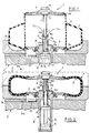
- the device 1 is associated with a press of the so-called "B.O.M.” type comprising, as well-known to those skilled in the art, a bed 2 on which a mold 3 suitable for tyre vulcanization is operatively mounted; said mold in the embodiment shown consists of a lower half-portion 3a and an upper half-portion 3b (not shown in Fig. 1) adapted to be moved close to each other so as to enclose a tyre 4 on work, previously disposed on the lower half-portion 3a.
- a vulcanization chamber 5 made of elastomeric material and having a substantially tubular structure, said chamber lending itself to be brought from an extended condition in which, as shown in Fig. 1, it stands upright from the middle of the lower half-portion 3a according to a cylindrical configuration, to a radially expanded condition in which, as shown in Fig. 2, it is inflated with steam under pressure within the tyre 4 closed in the mold 3.
- the vulcanization chamber 5 exhibits an upper end edge 5a sealingly fastened in known manner to a movable disc 6 coaxially fastened to a drive rod 7 operable by axial movement upon command of a fluid-operated actuator generally identified by 8.
- the vulcanization chamber 5 also exhibits a lower end edge 5b sealingly engaged to a fixed disc 9, rigidly connected to the upper end of the actuator 8 coaxially facing the inside of the lower mold half 3.
- actuator 8 essentially comprises a cylinder 10 within which a lower piston 11 integral with a lower end 7a of the drive rod 7 is sealingly and slidably housed. Following the admission of working fluid under pressure into the cylinder 10, the drive rod 7 is axially moved, upon command of the lower piston 11, from a maximally drawn-out position relative to the actuator 8 to which the extension of chamber 5 as shown in Fig. 1 corresponds, to a minimally drawn-out position relative to said actuator, to which the radial expansion of the chamber corresponds.
- the device 1 further comprises first and second stop means arranged to fix the drive rod positioning to the maximally drawn-out and minimally drawn-out positions relative to actuator 8.
- the first stop means substantially consists of the vulcanization chamber 5 itself which lends itself to be stretched taut and to consequently react to tensile stress between the fixed 9 and movable 6 sealing discs in order to stop the drive rod 7 movement in its maximally drawn-out position.
- the rod stroke to the maximally drawn-out position is automatically adjusted depending upon the longitudinal extension of the vulcanization chamber 5 in its maximally extended position, without being however necessary, unlike the known art, to modify the positioning of the upper disc 6 along the end portion of the drive rod 7 and/or replace the locating collars within the fluid-operated actuator 8.
- the upper disc 6 exhibits a fixed predetermined positioning, at the upper end 7b of the drive rod 7.
- the fluid-operated actuator 8 for the purpose of carrying out the shifting of the lower piston 11 and, as a result, of the drive rod 7, is provided to be fed with working fluid, conveniently water or steam, under a pressure included between 0.4 and 1.2 MPa.
- working fluid conveniently water or steam
- This expedient makes it possible to install the device in question on already existing presses of the B.O.M. type, by reducing therein the feed pressure of the fluid-operated actuator 8 so as to eliminate any risk of damages to the vulcanization chamber 5 by effect of the thrust exerted by the drive rod 7 in its maximally drawn-out position.
- the second stop means in turn comprises a pair of semi-cylindrical elements 12a, 12b to be moved close to the drive rod 7 at opposite positions, as shown in Fig. 5, in order to define a tubular locating sleeve 13 slidably passed through by the drive rod.
- This locating sleeve 13 exhibits a lower end 13a arranged to act in abutment on a locating seat 14 carried by the fluid-operated actuator 8, as well as an upper end 13b adapted to offer an abutment seat to stop the downstroke of the drive rod 7 to the minimally drawn-out position.
- the locating seat 14 is advantageously formed on an upper piston 15 operatively housed in the actuator 8, at a position overlying the lower piston 11 and slidably passed through by the drive rod 7.
- This expedient too makes it possible to install the device 1 on already existing presses of the B.O.M. type, the fluid-operated actuator of which is provided with an upper piston similar to the one shown in the accompanying drawings.
- the semi-cylindrical elements 12a, 12b forming the locating sleeve 13 can be easily withdrawn from the fluid-operated actuator 8 so as to be replaced in turn with semi-cylindrical elements of different length, depending upon the axial distance to be given to the movable disc 6 relative to the fixed disc 9 in the minimally drawn-out position of the drive rod 7.
- Each semi-cylindrical element 12a, 12b is also provided, in the vicinity of its upper end, with at least a radial retaining relief 16a, 16b arranged to act in abutment, as shown in Fig. 4, on the upper end of a collar 8a conveniently fastened to the upper end of the fluid-operated actuator 8, for stopping the locating sleeve 13 sliding towards the inside of the actuator, should the upper piston 15 during the conventional operating cycle of the vulcanization press move away from the upper end of the actuator to a greater extent than the sleeve 13 length.
- a retaining device of any known type and therefore not shown for example an elastic clip to be engaged into a groove formed in the body of each of the semi-cylindrical elements) preventing said elements from accidentally sliding off from said collar.
- the movable disc 6 is provided to be fastened to the drive rod 7 by a grasping head 17 fastened to the upper end 7a of the rod and arranged to be removably engaged, by quick coupling means 18 with a cylindrical collar 19 coaxially fastened to the movable disc.
- the first coupling means 18 comprises a plurality of pins 20 oscillatably received in respective housings circumferentially distributed in the grasping head 17.
- Pins 20 are simultaneously oscillating between an engagement position in which they radially project from respective openings 21a exhibited by the grasping head 17 to hold the movable disc 6 at an annular groove 22 formed on an inner cylindrical surface 19a of the cylindrical collar 19, and a disengagement position in which they are radially retracted within the grasping head 17 for enabling the free movement of the movable disc 6 relative to the rod 7.
- the shifting of pins 20 between the engagement and disengagement positions takes place by means of a driving bush 23 coaxially movable within the grasping head 17, between a retaining position in which, by an outer cylindrical surface 23a thereof, it acts on the pins 20 in order to keep them in the engaged position, and a release position in which, as shown by phantom line in Fig. 3, it releases the pins 20 in order to make their shifting to the disengaged position free.
- the displacement of the driving bush 23 from the retaining position to the release position takes place against the action of a return spring 24 operating between the grasping head 17 and the bush by means of a thrust element 25 shown in dotted line, to be inserted in an access opening 26 exhibited by the grasping head at the upper part thereof.
- the thrust element 25 can consist of a manual tool or an element belonging to an automated transport device of the vulcanization chambers 5, in the same manner as described in the above mentioned US Patent in the name of the same Applicant.
- the fastening of the grasping ring 28 takes place by utilizing as the threaded coupling 28a, the thread already present in conventional B.O.M. presses for locking the lower disc to the upper end of the fluid-operated actuator 8.
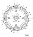
- the second quick coupling means 27 comprises a plurality of latches 29 housed in respective slide openings 29a circumferentially distributed in the grasping ring 28.
- Latches 29 are simultaneously movable between an engaged position in which, as shown by dotted line in Fig. 5, they project from the slide openings 29a radially towards the outside of the grasping ring 28, to a disengaged position in which they are radially retracted towards the ring inside.
- latches 29 engage the fixed disc, as shown in Fig. 4, at an annular groove 30 formed in an inner cylindrical surface 30a of the disc itself, whereas in the disengaged position said latches release the shifting of the fixed disc 9 from the grasping ring 28 and therefore from the vulcanization press as a whole.
- the latches shifting from the engaged position to the disengaged position occurs by means of a driving nut 31 rotatably housed in an annular cavity 32 formed coaxially in the grasping ring 28.
- a driving nut 31 rotatably housed in an annular cavity 32 formed coaxially in the grasping ring 28.
- a plurality of circumferential cams 32 each associated with one of the latches 29.
- the driving nut 31 is susceptible of angular rotation between a retaining position in which the cams 32 keep the latches 29 in the engaged position, to a release position in which said cams disengage the respective latches 29 so as to enable the free shifting of the same to the disengaged position, which will occur as soon as the fixed disc 9 is removed from the grasping ring 28.
- the angular rotation of the nut 31 is manually controlled by a bar 34 (Fig. 4) to be for example inserted in a cavity 34a formed frontally in the press bed 2, which is accessible only when the actuator has been raised from said bed and engages with an operating lever 35 fastened to the ring in cantilevered fashion.
- the control of the vulcanization chamber 5 by means of the device in question described above mainly as regards structure is as follows.
- the moving away of the movable disc 6 from the fixed disc 9 terminates as soon as a longitudinal tensioning of the vulcanization chamber 5 occurs, which is sufficient to counteract the thrust transmitted to the movable disc upon command of the fluid-operated actuator 8.
- this approaching step is caused by admitting working fluid between the lower piston 11 and upper piston 15.
- the upper piston 15 is urged upwardly as far as it stops against the upper end of the actuator 8, so as to give the upper end of the tubular locating sleeve 13 a predetermined positioning depending on the longitudinal extension of the semi-cylindrical elements 12a, 12b.
- This positioning will determine the stop position of the movable disc 6 when the drive rod 7 is in the minimally drawn-out position relative to actuator 8, so that the fixed and movable discs 9 and 6 exhibit the desired distance between centres depending upon the geometrical features of the tyre 4 on work.
- the lowering of the movable disc 6 takes place concurrently with the admission of a working fluid, generally steam under pressure, into the vulcanization chamber 5, so as to cause the radial expansion thereof within the closed mold 3.
- a working fluid generally steam under pressure
- Pressure exerted within the tyre 4 following the radial expansion of the vulcanization chamber 5 ensures the perfect adhering of the tyre 4 to the inner mold walls during the whole vulcanization step.
- the mold 3 When the vulcanization operation is over, the mold 3 is opened and the vulcanization chamber 5 is brought back to the extended condition by moving the movable disc 6 away from the fixed disc 9, concurrently with the withdrawal from the chamber of the previously introduced steam.
- the replacement of the vulcanization chamber 5 is required, for example because a vulcanization chamber having a greater axial extension is needed, it is sufficient to act on the first and second quick coupling means 18, 27 in order to enable the movable and fixed discs 6 and 9 to be disengaged together with the chamber 5 associated therewith.
- the installation of the new chamber will take place by merely engaging the respective movable 6 and fixed discs 9 to the first and second quick coupling means 18, 27 disposed in the grasping head 17 and grasping ring 28.
- the invention achieves important advantages.
Landscapes
- Engineering & Computer Science (AREA)
- Mechanical Engineering (AREA)
- Moulds For Moulding Plastics Or The Like (AREA)
- Heating, Cooling, Or Curing Plastics Or The Like In General (AREA)
- Control Of Position Or Direction (AREA)
Claims (10)
- Steuervorrichtung zum Umgestalten einer flexiblen, im wesentlichen schlauchförmigen Vulkanisationskammer (5) in einer Reifenvulkanisationspresse von einem axial aufgeweiteten Zustand in einen radial aufgeweiteten Zustand und umgekehrt- mit einer fluidbetriebenen Betätigungseinrichtung (8), die in einem Vulkanisationspressenbett (2) aufgenommen ist,- mit einer langgestreckten Antriebsstange (7), die koaxial von der fluidbetriebenen Betätigungseinrichtung (8) vorsteht und für eine Bewegung in die Richtung ihrer Längsachse angeordnet ist,- mit einem unteren Kolben (11), der in der Betätigungseinrichtung (8) zum Bewegen der Antriebsstange (7) aus einer minimal ausgefahrenen Stellung in eine maximal ausgefahrene Stellung bezüglich der Betätigungseinrichtung aufgenommen ist,- mit einer ersten Scheibe (6), die lösbar an einem distalen Ende der Antriebsstange (7) angebracht und abdichtend an dem oberen Endrand der Vulkanisationskammer (5) festgelegt ist,- mit einer zweiten Scheibe (9), die lösbar an der fluidbetriebenen Betätigungseinrichtung (8) angebracht und abdichtend an dem unteren Endrand der Vulkanisationskammer (5) festgelegt ist,- mit einer ersten Anschlageinrichtung zur Lagebegrenzung der Antriebsstange auf die maximal ausgefahrene Position,- mit einer zweiten Anschlageinrichtung zur Lagebegrenzung der Antriebsstange auf die minimal ausgefahrene Stellung,dadurch gekennzeichnet, daß sie weiterhin- einen Greifkopf (17), der von dem distalen Ende der Antriebsstange (7) getragen wird, und eine erste Schnellkupplungseinrichtung (18) für eine lösbare Eingriffsherstellung der ersten Scheibe (6) an der Stange aufweist und- einen Greifring (28) hat, der von der fluidbetriebenen Betätigungseinrichtung (8) getragen wird und eine zweite Schnellkupplungseinrichtung (27) für eine lösbare Eingriffsherstellung der zweiten Scheibe (9) hat,- wobei die erste Anschlageinrichtung die schlauchförmige Vulkanisationskammer (5) aufweist, deren Wand auf Zugspannung zwischen der ersten Scheibe (6) und der zweiten Scheibe (9) reagiert, wodurch die Bewegung der Antriebsstange (7) in der maximal ausgefahrenen Position angehalten wird und- wobei die zweite Anschlageinrichtung wenigstens zwei halbzylindrische Elemente (12a, 12b) aufweist, die angrenzend an die Antriebsstange (7) auf ihren gegenüberliegenden Seiten angeordnet sind, wodurch eine rohrförmige Positionierhülse (13) gebildet wird, durch die die Antriebsstange (7) gleitend verschiebbar hindurchgeht und die ein unteres Ende (13a) angrenzend an einen Positioniersitz (14), der von der fluidbetriebenen Betätigungseinrichtung (8) getragen wird, und ein oberes Ende (13b) hat, das als ein Anschlagsitz zur Begrenzung eines Antriebsstangen-Einziehhubs auf die minimal ausgefahrene Stellung wirkt.
- Vorrichtung nach Anspruch 1, dadurch gekennzeichnet, daß die erste Schnellkupplungseinrichtung (18)- einen zylindrischen Bund (19), der koaxial an der beweglichen Scheibe (6) befestigt und für den Eingriff mit dem Greifkopf (17) ausgelegt ist,- eine Vielzahl von Stiften (20), die hin und her bewegbar in zugehörigen, am Umfang verteilten Gehäusen (21) in dem Greifkopf (17) aufgenommen sind und gleichzeitig zwischen einer Eingriffsstellung, in der sie radial aus den jeweiligen Öffnungen (21a) vorstehen, die der Greifkopf (17) zum Halten der beweglichen Scheibe (6) an einer in dem Bund (19) ausgebildeten Ringnut (22) aufweist, und einer Nichteingriffsstellung hin und her bewegbar sind, in welcher sie radial in den Kopf (17) eingezogen sind, so daß die freie Bewegung der beweglichen Scheibe (6) möglich ist, und- eine Antriebsbüchse (23) aufweist, die koaxial in dem Greifkopf (17) zwischen einer Rückhaltestellung, in der sie auf die Stifte (20) für ihr Halten in der Eingriffsstellung wirkt, und einer Freigabestellung bewegbar ist, in welcher sie die Stifte (20) freigibt, damit deren Bewegung zur Nichteingriffsstellung möglich ist.
- Vorrichtung nach Anspruch 2, dadurch gekennzeichnet, daß die Antriebsbüchse (23) axial aus der Rückhaltestellung in die Freigabestellung entgegen der Wirkung einer Rückholfeder (24) durch Wirkung eines Schubelements (25) bewegbar ist, das in eine Zugangsöffnung (26) einführbar ist, die der Greifkopf (17) an seinem oberen Teil aufweist.
- Vorrichtung nach Anspruch 1, dadurch gekennzeichnet, daß der Greifring (28) an der fluidbetriebenen Betätigungseinrichtung (8) durch eine Gewindekupplung (28a) festgelegt ist.
- Vorrichtung nach Anspruch 1, dadurch gekennzeichnet, daß die zweite Schnellkupplungseinrichtung (27)- eine Vielzahl von Riegeln (29), die in zugeordneten, am Umfang in dem Greifring verteilten Gleitöffnungen (29a) aufgenommen und gleichzeitig zwischen einer Eingriffsstellung, in der sie radial aus den Gleitöffnungen (29a) auf die Außenseite des Greifrings (27) für den Eingriff der feststehenden Scheibe (9) mit einer an ihrer inneren Zylinderfläche (30a) ausgebildeten Ringnut (30) vorstehen, und einer Nichteingriffsstellung bewegbar sind, in welcher sie radial zur Innenseite des Rings zum Freigeben der feststehenden Scheibe (9) eingefahren sind, und- eine Antriebsmutter (31) aufweist, die drehbar in einer Ringaussparung (32) aufgenommen ist, die koaxial in dem Greifring (28) ausgebildet ist und an ihrem äußeren Umfangsrand eine Vielzahl von Umfangsnocken (33) trägt, von denen jeder einem der Riegel (29) zugeordnet ist, wobei die Antriebsmutter (31) zwischen einer Rückhaltestellung, in der die Nocken (33) die Riegel (29) in der Eingriffsstellung halten, und einer Freigabestellung im Winkel drehbar ist, in der die Nocken (33) den Eingriff mit den zugehörigen Riegeln (29) lösen, um deren freie Bewegung in die Nichteingriffsstellung zu ermöglichen.
- Vorrichtung nach Anspruch 1, dadurch gekennzeichnet, daß der Positioniersitz (14) an einem oberen Kolben (15) ausgebildet ist, der gleitend verschiebbar in der fluidbetriebenen Betätigungseinrichtung (8) aufgenommen ist und sich gleitend verschiebbar durch die Antriebsstange (7) erstreckt.
- Vorrichtung nach Anspruch 6, dadurch gekennzeichnet, daß jedes der halbzylindrischen Elemente (12a, 12b) in der Nähe ihres oberen Endes mit wenigstens einer radialen Halteerhebung (16a, 16b) versehen ist, die für ein Wirken anschlagend am oberen Ende der fluidbetriebenen Betätigungseinrichtung (8) zum Anhalten der Gleitbewegung der Positionierhülse (13) zur Innenseite der Betätigungseinrichtung angeordnet ist, wenn der obere Kolben (15) sich von dem oberen Ende der Betätigungseinrichtung selbst weg bewegt.
- Vorrichtung nach Anspruch 1, dadurch gekennzeichnet, daß die fluidbetriebene Betätigungseinrichtung (8) mit einem Arbeitsfluid beschickt wird, das einen Druck zwischen 0,4 und 1,2 MPa hat.
- Verfahren zum Steuern der Umgestaltung einer flexiblen, im wesentlichen schlauchförmigen Vulkanisationskammer (5) in einer Reifenvulkanisationspresse, wobei die Vulkanisationskammer einen oberen Endrand (5a), der in Eingriff mit einer ersten abdichtenden Scheibe (6) steht, die axial auf Befehl einer an einem Vulkanisationspressenbett (2) festgelegten fluidbetriebenen Betätigungseinrichtung (8) bewegbar ist, und einen unteren Endrand (5b) hat, der mit einer zweiten abdichtenden Scheibe (9) in Eingriff steht, die bezüglich der fluidbetriebenen Betätigungseinrichtung (8) festgelegt ist, wobei das Verfahren die Schritte aufweist- Bewegen der ersten Scheibe (6) weg von der zweiten Scheibe (9) aufgrund der Wirkung, die von der fluidbetriebenen Betätigungseinrichtung (8) ausgeübt wird, so daß die Vulkanisationskammer (5) axial in eine im wesentlichen zylindrische Form umgestaltet wird, wobei die Vulkanisationskammer (5) in Längsrichtung unter Zug gesetzt wird,- Bewegen der ersten Scheibe nahe zu der zweiten Scheibe (9) bis zum Anliegen an der Anschlageinrichtung und Einführen eines Arbeitsfluids in die Vulkanisationskammer (5), um die Kammer zum radialen Aufweiten in einer Form (3) der Presse zu bringen, dadurch gekennzeichnet, daß es weiterhin den Schritt aufweist- Anhalten der Bewegung der ersten Scheibe (6) entfernt von der zweiten Scheibe (9), wenn das Unter-Zugspannung-Setzen der Vulkanisationskammer (5) in Längsrichtung dem Druck entgegenwirkt, der auf die erste Scheibe (6) von der fluidbetriebenen Betätigungseinrichtung (8) übertragen wird.
- Verfahren nach Anspruch 9, dadurch gekennzeichnet, daß während des Wegbewegungsschritts der fluidbetriebenen Betätigungseinrichtung (8) Arbeitsfluid mit einem Druck zwischen 0,4 und 1,2 MPa zugeführt wird.
Applications Claiming Priority (2)
| Application Number | Priority Date | Filing Date | Title |
|---|---|---|---|
| ITMI912323A IT1251381B (it) | 1991-08-30 | 1991-08-30 | Dispositivo di comando per camere di vulcanizzazione in presse di vulcanizzazione, e procedimento di comando attuato da detto dispositivo. |
| ITMI912323 | 1991-08-30 |
Publications (2)
| Publication Number | Publication Date |
|---|---|
| EP0529331A1 EP0529331A1 (de) | 1993-03-03 |
| EP0529331B1 true EP0529331B1 (de) | 1996-03-06 |
Family
ID=11360595
Family Applications (1)
| Application Number | Title | Priority Date | Filing Date |
|---|---|---|---|
| EP92112887A Expired - Lifetime EP0529331B1 (de) | 1991-08-30 | 1992-07-29 | Betätigungseinrichtung für Vulkanisierkammern in Vulkanisierpressen und das in die Praxis umgesetzte Verfahren |
Country Status (7)
| Country | Link |
|---|---|
| US (1) | US5393480A (de) |
| EP (1) | EP0529331B1 (de) |
| JP (1) | JP3273062B2 (de) |
| BR (1) | BR9203438A (de) |
| DE (1) | DE69208775T2 (de) |
| ES (1) | ES2087362T3 (de) |
| IT (1) | IT1251381B (de) |
Families Citing this family (12)
| Publication number | Priority date | Publication date | Assignee | Title |
|---|---|---|---|---|
| JP3001747B2 (ja) * | 1993-04-05 | 2000-01-24 | 株式会社神戸製鋼所 | タイヤ加硫プレス用ブラダ組立体の取付装置及び搬送装置 |
| JP2866027B2 (ja) * | 1995-06-06 | 1999-03-08 | 三菱重工業株式会社 | タイヤ加硫機用中心機構 |
| US6416305B1 (en) * | 1998-10-26 | 2002-07-09 | Mcneil & Nrm, Inc. | Tire curing press center mechanism |
| JP4323050B2 (ja) * | 1999-03-16 | 2009-09-02 | 株式会社ブリヂストン | タイヤ加硫装置及びブラダ着脱方法並びにタイヤ製造方法 |
| US6217307B1 (en) * | 1999-04-12 | 2001-04-17 | Pirelli Tire Llc | Spring spacer for bladder assembly in a tire curing press |
| JP3865354B2 (ja) | 2000-03-02 | 2007-01-10 | 高木産業株式会社 | 細胞又は組織の培養方法 |
| JP4490916B2 (ja) * | 2003-07-25 | 2010-06-30 | 不二商事株式会社 | タイヤの加硫方法及び同方法を実施するための加硫機 |
| US7513763B1 (en) | 2007-06-04 | 2009-04-07 | Mcneil & Nrm, Inc. | Tire press center mechanism |
| JP6735079B2 (ja) * | 2015-10-15 | 2020-08-05 | Toyo Tire株式会社 | ブラダー固定ユニット |
| CN107009830A (zh) * | 2017-05-17 | 2017-08-04 | 青岛软控机电工程有限公司 | 一种连接方法及装置 |
| CN109895029B (zh) * | 2019-03-29 | 2023-12-29 | 海默科技(集团)股份有限公司 | 一种基于水下流量计的下放工具 |
| CN118144168B (zh) * | 2024-05-09 | 2024-09-24 | 张家港市华申工业橡塑制品有限公司 | 一种自动化橡胶加压硫化机及自动化加压硫化方法 |
Family Cites Families (15)
| Publication number | Priority date | Publication date | Assignee | Title |
|---|---|---|---|---|
| US2559119A (en) * | 1950-01-25 | 1951-07-03 | Paul A Frank | Tire curing apparatus and method |
| US2970342A (en) * | 1957-10-17 | 1961-02-07 | Cleveland Trust Co | Vulcanizing press |
| US3487507A (en) * | 1967-11-29 | 1970-01-06 | Nrm Corp | Actuating device and control for tire curing press |
| DE1808742A1 (de) * | 1968-11-14 | 1970-06-11 | Uniroyal Englebert Ag | Presse zur Vulkanisation von Luftreifen |
| BE757098A (fr) * | 1969-10-06 | 1971-03-16 | Kobe Steel Ltd | Mecanisme central pour presses a faconner et vulcaniser les pneumatiques |
| US4527946A (en) * | 1982-09-29 | 1985-07-09 | Nrm Corporation | Tire curing press with pop-up, rotating nozzle |
| JPS61219606A (ja) * | 1985-03-26 | 1986-09-30 | Kobe Steel Ltd | タイヤ加硫プレス |
| US4695234A (en) * | 1985-03-29 | 1987-09-22 | Kabushiki Kaisha Kobe Seiko Sho | Central mechanism in a tire vulcanizing press |
| DE3515203A1 (de) * | 1985-04-26 | 1986-10-30 | Concordia Sprecher-Schaltgeräte GmbH, 7024 Filderstadt | Gekapselter lastschalter |
| US4597729A (en) * | 1985-09-23 | 1986-07-01 | Nrm Corporation | Tire curing press and loader |
| JPS6280010A (ja) * | 1985-10-03 | 1987-04-13 | S G:Kk | タイヤ加硫機のバグシリンダ制御装置 |
| US4684338A (en) * | 1986-07-03 | 1987-08-04 | The Goodyear Tire & Rubber Company | Rod gland and hub assembly for tire curing press |
| IT1198209B (it) * | 1986-12-01 | 1988-12-21 | Pirelli | Miglioramenti alle presse di vulcanizzazione per pneumatici |
| US4768937A (en) * | 1987-02-02 | 1988-09-06 | Nrm Corporation | Tire curing press |
| JPH0637058B2 (ja) * | 1989-08-02 | 1994-05-18 | 三菱重工業株式会社 | タイヤ加硫機の中心機構 |
-
1991
- 1991-08-30 IT ITMI912323A patent/IT1251381B/it active IP Right Grant
-
1992
- 1992-07-29 ES ES92112887T patent/ES2087362T3/es not_active Expired - Lifetime
- 1992-07-29 EP EP92112887A patent/EP0529331B1/de not_active Expired - Lifetime
- 1992-07-29 DE DE69208775T patent/DE69208775T2/de not_active Expired - Fee Related
- 1992-08-25 US US07/934,392 patent/US5393480A/en not_active Expired - Lifetime
- 1992-08-28 BR BR929203438A patent/BR9203438A/pt not_active IP Right Cessation
- 1992-08-31 JP JP23173092A patent/JP3273062B2/ja not_active Expired - Fee Related
Also Published As
| Publication number | Publication date |
|---|---|
| EP0529331A1 (de) | 1993-03-03 |
| ITMI912323A0 (it) | 1991-08-30 |
| IT1251381B (it) | 1995-05-09 |
| ES2087362T3 (es) | 1996-07-16 |
| JPH05261736A (ja) | 1993-10-12 |
| ITMI912323A1 (it) | 1993-03-02 |
| DE69208775D1 (de) | 1996-04-11 |
| JP3273062B2 (ja) | 2002-04-08 |
| US5393480A (en) | 1995-02-28 |
| BR9203438A (pt) | 1993-04-06 |
| DE69208775T2 (de) | 1996-10-02 |
Similar Documents
| Publication | Publication Date | Title |
|---|---|---|
| EP0529331B1 (de) | Betätigungseinrichtung für Vulkanisierkammern in Vulkanisierpressen und das in die Praxis umgesetzte Verfahren | |
| US3740293A (en) | Tire building machine | |
| EP0270022B1 (de) | Reifenvulkanisierpresse | |
| US3741696A (en) | Segmented tire mold | |
| JP5705132B2 (ja) | タイヤの加硫装置 | |
| US11697261B2 (en) | Process and apparatus for building tyres | |
| US4338069A (en) | Tire press | |
| US5409361A (en) | Center mechanism of tire curing press | |
| US3260782A (en) | Press for shaping and curing pneumatic tires | |
| EP3849787B1 (de) | Reifenaufbautrommel mit einer blase | |
| JPH02107408A (ja) | タイヤプレスにおけるスタンディングウエルポスト型中心機構 | |
| DE69918890T2 (de) | Reifenvulkanisiervorrichtung mit einem segmentierten Formwerkzeug | |
| JP3300744B2 (ja) | タイヤ加硫機の中心機構 | |
| JP2002018856A (ja) | タイヤ加硫機及びタイヤ加硫方法 | |
| US2974714A (en) | Method and apparatus for applying an uncured rubber covering to a tire carcass | |
| EP2578385B1 (de) | Verfahren und Vorrichtung zum Tragen und Bewegen einer Reifenaufbautrommel | |
| JPS5830138B2 (ja) | 生タイヤの上方ビ−ドを加硫プレスの金型の上方部分内に心決めしかつ位置決めする方法および装置 | |
| US5405568A (en) | Two-piece segmented tire mold and method of molding | |
| KR0149977B1 (ko) | 블래더리스타이어가류기에의 생타이어장착방법 및 그 장치 | |
| JP3569170B2 (ja) | タイヤ加硫機の中心機構 | |
| EP0669202A2 (de) | Reifenvulkanisierpresse | |
| CN222096714U (zh) | 胶囊操纵装置及硫化机 | |
| CA1091408A (en) | Apparatus for positioning and curing a pre-shaped tire carcass | |
| JP2000202834A (ja) | タイヤ加硫設備 | |
| JPS626964B2 (de) |
Legal Events
| Date | Code | Title | Description |
|---|---|---|---|
| PUAI | Public reference made under article 153(3) epc to a published international application that has entered the european phase |
Free format text: ORIGINAL CODE: 0009012 |
|
| AK | Designated contracting states |
Kind code of ref document: A1 Designated state(s): DE ES FR GB |
|
| 17P | Request for examination filed |
Effective date: 19930726 |
|
| RAP1 | Party data changed (applicant data changed or rights of an application transferred) |
Owner name: PIRELLI COORDINAMENTO PNEUMATICI S.P.A. |
|
| 17Q | First examination report despatched |
Effective date: 19941108 |
|
| GRAH | Despatch of communication of intention to grant a patent |
Free format text: ORIGINAL CODE: EPIDOS IGRA |
|
| GRAA | (expected) grant |
Free format text: ORIGINAL CODE: 0009210 |
|
| AK | Designated contracting states |
Kind code of ref document: B1 Designated state(s): DE ES FR GB |
|
| REF | Corresponds to: |
Ref document number: 69208775 Country of ref document: DE Date of ref document: 19960411 |
|
| REG | Reference to a national code |
Ref country code: ES Ref legal event code: BA2A Ref document number: 2087362 Country of ref document: ES Kind code of ref document: T3 |
|
| ET | Fr: translation filed | ||
| REG | Reference to a national code |
Ref country code: ES Ref legal event code: FG2A Ref document number: 2087362 Country of ref document: ES Kind code of ref document: T3 |
|
| PLBE | No opposition filed within time limit |
Free format text: ORIGINAL CODE: 0009261 |
|
| STAA | Information on the status of an ep patent application or granted ep patent |
Free format text: STATUS: NO OPPOSITION FILED WITHIN TIME LIMIT |
|
| 26N | No opposition filed | ||
| REG | Reference to a national code |
Ref country code: GB Ref legal event code: IF02 |
|
| PGFP | Annual fee paid to national office [announced via postgrant information from national office to epo] |
Ref country code: FR Payment date: 20060717 Year of fee payment: 15 |
|
| PGFP | Annual fee paid to national office [announced via postgrant information from national office to epo] |
Ref country code: GB Payment date: 20060726 Year of fee payment: 15 |
|
| PGFP | Annual fee paid to national office [announced via postgrant information from national office to epo] |
Ref country code: DE Payment date: 20060831 Year of fee payment: 15 |
|
| GBPC | Gb: european patent ceased through non-payment of renewal fee |
Effective date: 20070729 |
|
| PG25 | Lapsed in a contracting state [announced via postgrant information from national office to epo] |
Ref country code: DE Free format text: LAPSE BECAUSE OF NON-PAYMENT OF DUE FEES Effective date: 20080201 |
|
| PG25 | Lapsed in a contracting state [announced via postgrant information from national office to epo] |
Ref country code: GB Free format text: LAPSE BECAUSE OF NON-PAYMENT OF DUE FEES Effective date: 20070729 |
|
| REG | Reference to a national code |
Ref country code: FR Ref legal event code: ST Effective date: 20080331 |
|
| PG25 | Lapsed in a contracting state [announced via postgrant information from national office to epo] |
Ref country code: FR Free format text: LAPSE BECAUSE OF NON-PAYMENT OF DUE FEES Effective date: 20070731 |
|
| PGFP | Annual fee paid to national office [announced via postgrant information from national office to epo] |
Ref country code: ES Payment date: 20080728 Year of fee payment: 17 |
|
| REG | Reference to a national code |
Ref country code: ES Ref legal event code: FD2A Effective date: 20090730 |
|
| PG25 | Lapsed in a contracting state [announced via postgrant information from national office to epo] |
Ref country code: ES Free format text: LAPSE BECAUSE OF NON-PAYMENT OF DUE FEES Effective date: 20090730 |