EP0529491B1 - Roue de véhicule - Google Patents
Roue de véhicule Download PDFInfo
- Publication number
- EP0529491B1 EP0529491B1 EP92114113A EP92114113A EP0529491B1 EP 0529491 B1 EP0529491 B1 EP 0529491B1 EP 92114113 A EP92114113 A EP 92114113A EP 92114113 A EP92114113 A EP 92114113A EP 0529491 B1 EP0529491 B1 EP 0529491B1
- Authority
- EP
- European Patent Office
- Prior art keywords
- rim
- flange
- wheel assembly
- tire
- removable
- Prior art date
- Legal status (The legal status is an assumption and is not a legal conclusion. Google has not performed a legal analysis and makes no representation as to the accuracy of the status listed.)
- Expired - Lifetime
Links
Images



Classifications
-
- B—PERFORMING OPERATIONS; TRANSPORTING
- B60—VEHICLES IN GENERAL
- B60B—VEHICLE WHEELS; CASTORS; AXLES FOR WHEELS OR CASTORS; INCREASING WHEEL ADHESION
- B60B25/00—Rims built-up of several main parts ; Locking means for the rim parts
- B60B25/22—Other apurtenances, e.g. for sealing the component parts enabling the use of tubeless tyres
Definitions
- This invention relates to a wheel assembly for tubeless pneumatic tires according to the preamble of claim 1.
- the multi-piece rim generally includes a rim with an integral bead seat flange and a detachable bead seat flange that is retained by a removable locking means, such as a lock-ring.
- a removable locking means such as a lock-ring.
- the beads of the tire are retained between the two flanges and upon inflation the tire seals airtightly against the flanges.
- the lock-ring is seated in an annular groove formed in the rim thus locking the bead flange securely in position.
- Tires mounted on multi-piece rims are inflated to high pressures in the range of 5,5 x 10⁵ to 7,5 x 10⁵ Pa (80 to 110 psi).
- the resultant forces at the bead restraining flanges are very high. Improper assembly of the rim or attempts to disassemble the wheel assembly while the tire is inflated can result in the detachable flange and lock rim dislodging and being thrown at high velocities.
- Depressurization is provided if an attempt is made to remove the flange from an inflated wheel assembly (see e.g. EP-A-284.507).
- a wheel assembly 10 for a tubeless pneumatic tire 11 is described.
- the wheel assembly 10 comprises a rim 12 for supporting the tire 11, a flange 14 removably attached to the rim for engaging a bead area of the tire 11, and a plurality of spaced means 30.
- the assembled rim 12 and flange 14 together with the tire 11 form an air-tight chamber 19 for pressurization.
- the plurality of spaced means 30 secure the flange 14 to the rim 12 and relieve pressurization from a mounted and inflated tire in the event the flange 14 is loosened from the rim 12.
- the rim 12 and flange 14 have a plurality of circumferentially spaced holes 20, 22.
- the holes 20 of the rim 12 are aligned with the holes 22 of the flange 14 to form a plurality of openings 25.
- the openings 25 extend from the flange 14 to the rim 12.
- the means 30 for securing and pressure relieving includes removable means 32 for applying axial force between the flange 14 and the rim 12.
- One of the removable means 32 is located in each of the respectively aligned flange and rim holes 20.
- the securing and pressure relieving means 30 further includes a plurality of airway passages 60 communicating with the air chamber 19 and the openings 25 and also includes means 33 for air tight sealing and unsealing of the airway passage 60 communicating with the opening 25 in which the removable means 32 is located upon secure assembly and disassembly of the flange 14 to the rim 12.
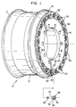
- Fig. 1 is a perspective view of the wheel assembly.
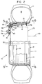
- Fig. 2 is a plan view of the wheel assembly attached to a hub.
- the wheel assembly is shown with tire and bead retainer.
- the view has a portion of the wheel assembly cut away to illustrate various components of the assembly.
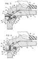
- Fig. 3 is an enlarged view of a portion of the wheel assembly taken along lines 3-3 of Fig. 5.
- Fig. 4 is a further view of the portion of the wheel assembly shown in Fig. 3, the removable means 32 being illustrated in a loosened position.
- Fig. 5 is a first side view of the wheel assembly.
- Fig. 6 is a second or opposite side view of the wheel assembly.
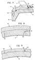
- Fig. 7 is an enlarged view of a portion of the wheel assembly, the view being taken from Fig. 5 along lines 7-7.
- Fig. 8 is a view of the removable flange and rim taken from Fig. 3 along lines 8-8.
- Fig. 9 is a view of the removable flange and rim taken from Fig. 3 along lines 9-9.
- Fig. 10 is a cross-sectional view of a portion of a pair of wheel assemblies attached to a hub, illustrating a dual wheel mounting configuration.
- Bead means that part of the tire comprising an annular tensile member wrapped by ply cords and shaped, with or without other reinforcement elements such as slippers, chippers, apexes, toe guards and chafers, to fit the design rim.
- “Circumferential” means lines or directions extending along the perimeter of the surface of the annular rim perpendicular to the axial direction.
- “Lateral” means an axial direction.
- Ring and radially are used to mean directions radially toward or away from the axis of rotation of the wheel assembly.
- Ration means the metal support for the tire or tire and tube assembly on the wheel. The beads of a tire are seated on the rim.
- Fig. 1 illustrates a wheel assembly according to the present invention, the wheel assembly being designated by reference numeral 10.
- the wheel assembly 10 includes a rim 12, a removable bead flange 14, and a plurality of spaced means 30 for securing the flange to the rim and for relieving pressurization from a mounted and inflated tire in the event the flange is loosened from the rim.
- the spaced means 30 includes a removable means 32; one such means is shown detached from the wheel assembly 10.
- the detached removable means 32 is shown with an elastomeric "O"-ring 33.
- the "O"-ring 33 fits over a threaded stud 34 and is positioned between the rim 12 and the removable means 32.
- the rim 12 has an axial end 16 with a plurality of openings 40 for attaching the wheel assembly 10 to the hub of a vehicle.
- the flange 14 includes a plurality of holes 22 which, when the flange is attached to the rim 12, align with the holes 20 in rim 12 thus forming openings 25 that extend through the wheel assembly 10.
- Projecting from the holes 20 in the rim 12 are a plurality of threaded studs 34 which extend through holes 22 of the flange 14 and thereby provide means for securing the flange 14 to the rim 12.
- the rim 12 also has a large center opening 18 at its axial end 16.
- the slots 80 are provided to facilitate the mounting of a pair of wheel assemblies in a dual wheel mounting configuration.
- Fig. 2 illustrates the wheel assembly 10 with a tire 11 mounted.
- the tire 11 has a bead retaining device 13 positioned between the beads of the tire 11.
- the bead retaining device 13 as shown is described in U. S. Patent 5,000,240.
- the device 13 is an optional component that can be used in conjunction with the wheel assembly 11 of the present invention.
- the phantom or dashed lines of Fig. 2 represent an axle 70 and a hub 72 of a vehicle.
- the hub has a plurality of threaded studs 74 that project through the openings 40 of the rim 12 to provide a means for securing the wheel assembly 10 to a vehicle by attachment of threaded nuts 76 to the studs 74.
- An air inflation valve 78 is shown attached to the rim, the valve 78 being positioned between the beads of a tire 11 to facilitate inflation of the tire 11.
- the space between the inside of the tire 11 and the assembled flange rim forms an air tight chamber 19.
- a means 30 for securing and pressure relieving is shown in Fig. 2 and an enlarged view is shown in Fig. 3.
- the means 30 for securing and pressure relieving includes a threaded stud 34 press fit into the rim hole 20 and extending through the aligned flange hole 22.
- a removable means 32 for applying an axial force between the flange 14 and the rim 12 is shown.
- the removable means 32 is a threaded nut.
- the nut 32 has a hexagonal shaped head 35 for tightening, a circular collar 36 for securing the flange, and a cylindrical extension 38 with a chamfered end 37.
- the chamfered end 37 contacts and compresses an elastomeric "O"-ring 33, the "O"-ring 33 being positioned over the stud 34.
- collar 36 engages the flange 14, the flange 14 is forced against the rim 12, and the collar limits the travel of removable means 32. This travel limiting aspect assures that the "O"-ring 33 is not damaged during assembly.
- annular sealing ring 50 Positioned between the removable flange 14 and the rim 12 is an annular sealing ring 50.
- the annular sealing ring ensures that the periphery of the flange 14 to rim 12 interface is sealed to allow air retention within a tire mounted on wheel assembly 11.
- the securing and pressure relieving means 30 includes a plurality of air passages 60 communicating with the air chamber 19 and the openings 25 in which the removable means 32 are located.
- the means 30 also includes means 33 for air tightly sealing and unsealing the air passage 60.
- the means 33 is a plurality of "O"-rings 33. As the removable means 32 is tightened upon assembly the "O"-ring 33 is compressed between the removable means 32 and the rim 12 and the compressed "O"-ring airtightly seals the air passage 60.
- An air passage 60 is formed by a passage 60 in the rim 12, of circular cross-section, and by a slot 64 in the flange.
- the circular passages 60, 62 extend from the opening 25, through the rim 12, to an area under the flange 14.
- the flange includes a slot 64.
- the slots 64 are aligned with the circular passage 62 of the rim and extend from the air chamber 19 to the circular passage 62.
- the cylindrical extension 38 of the removable means 32 has a diameter less than the flange opening 22.
- the flange hole 22 includes a counterbored opening 23 large enough to accommodate the removable means collar 36 and a through hole 27 of a diameter larger than the cylindrical extension 38.
- the rim hole 20 includes a through hole 28 into which the stud 34 is pressed and a larger counterbored opening 29 with which the air passage 60 communicates.
- the counterbored opening 29 has diameter large enough to accept the "O"-ring 33 and preferably is smaller than the flange through hole 27.
- Fig. 5 and 6 show the side views of the wheel assembly 10.
- Fig. 5 is a view looking at the removable flange side of the assembly. The view shows a typical pattern of hub attachment holes 40 and the large central opening 18 of the rim 12.
- a portion of the removable flange 14 with spaced means 30 is shown. Interposed between each means 30 is a slot 80.
- the slot 80 is of sufficient size to accommodate the hexagonal head 35 of the removable means 32, the head 35 being adapted to nest within the flange slot 80. This feature is particularly useful when dual wheel mounting is required.
- a pair of wheel assemblies 10 can be tandemly mounted to a vehicle hub.
- each of the means 30 for securing the removable flange and pressure relieving nests within a flange slot 80 of the opposite wheel assembly A portion of each of the means 30 for securing the removable flange and pressure relieving nests within a flange slot 80 of the opposite wheel assembly.
- the axial ends 16 of the rim assemblies 10 abut each other.
- the mounting holes of each wheel are located so that, when end 16 of the two wheels abut, the mounting holes align and the means 30 of each wheel are in the slots 80 of the other wheel.
- the removable flange 14 is axially aligned with or inward of the axial extent of the rim's axial end 16.
- a portion of flange 14 is removed and the annular seal 50 is shown interposed between the flange and the rim.
- Six of the openings 25 are revealed.
- the stud 34 with an "O"-ring 33 is illustrated at three of the openings 25. In one such opening 25 the "O"-ring 33 is partially cut away illustrating the airway passage 60. In the three remaining exposed openings 25 the stud 34 with airway passage 60 is shown without "O"-rings 33.
- spaced means 30 are used for securing the flange and relieving pressurization from an inflated tire, but a greater or lesser number can be incorporated into the design. It is recommended that at least four and preferably six or more such means be utilized. In any event the number of means must be adequate to reduce tire pressure prior to dislodgement of the flange.
- Fig. 6 is a view of the wheel assembly 10 opposite to the view of Fig. 5, the view in Fig. 6 looking toward the side of the rim 12 having integral flange 17.
- the press fit attachment of the studs 34 to the rim 12 is illustrated, as well as a partial sectional view of the wheel assembly 10 exposing the airpassage slots 64 in the removable flange 14.
Landscapes
- Engineering & Computer Science (AREA)
- Mechanical Engineering (AREA)
- Tires In General (AREA)
- Measuring Fluid Pressure (AREA)
Claims (10)
- Assemblage de roue (10) pour un bandage pneumatique sans chambre à air, l'assemblage de roue possédant une jante (12) pour supporter le bandage pneumatique, un rebord (14) fixé de manière amovible à la jante (12) pour venir se mettre en contact avec une zone de talon du bandage pneumatique, la jante (12) et le rebord (14) à l'état assemblé formant, conjointement avec le bandage pneumatique (11), une chambre (19) étanche à l'air à des fins de mise sous pression, l'assemblage de roue (10) possédant plusieurs moyens espacés (30) pour fixer le rebord (14) à la jante (12) et pour supprimer la mise sous pression d'un bandage pneumatique monté et gonflé (11) dans le cas où le rebord se détache de la jante, les moyens espacés (30) englobant des moyens amovibles (32) pour exercer une force axiale entre le rebord et la jante, caractérisé en ce que, lorsqu'on desserre un des moyens amovibles (30), on supprime la mise sous pression du bandage pneumatique.
- Assemblage de roue selon la revendication 1,
dans lequel la jante (12) et le rebord (14) possèdent plusieurs trous (20) espacés en direction circonférentielle, les trous pratiqués dans la jante (12) se trouvant en alignement avec les trous (22) pratiqués dans le rebord (14) pour former plusieurs ouvertures (25) s'étendant depuis le rebord (14) jusqu'à la jante (12); et
dans lequel un desdits moyens amovibles (32) est situé dans chacun des trous (20) pratiqués dans la jante et dans le rebord, se trouvant respectivement en alignement. - Assemblage de roue selon la revendication 2, dans lequel les moyens espacés (30) comprennent plusieurs passages pour l'air (60) communiquant avec la chambre (19) pour l'air et les ouvertures (25), ainsi que des moyens (33) pour procurer et supprimer l'étanchéification à l'air du passage pour l'air (60) communiquant avec l'ouverture (25) dans laquelle on place le moyen amovible (32) lors de l'assemblage et du désassemblage du rebord (14) à la jante (12).
- Assemblage de roue selon la revendication 2, dans lequel le moyen amovible (32) comprend un goujon fileté (34) fixé à la jante, ainsi qu'un écrou amovible.
- Assemblage de roue selon la revendication 3, dans lequel le moyen (33) pour étancher le passage pour l'air comprend un joint torique élastomère.
- Assemblage de roue selon la revendication 1, possédant un joint étanche annulaire (50), le joint étanche annulaire étant situé entre le rebord amovible (14) et la jante (12).
- Assemblage de roue selon la revendication 1, comprenant au moins quatre moyens espacés (30) pour fixer le rebord (14) à la jante (12) et pour supprimer la mise sous pression.
- Assemblage de roue selon la revendication 7, comprenant au moins six moyens espacés (30) pour fixer le rebord (14) à la jante (12) et pour supprimer la mise sous pression.
- Assemblage de roue selon la revendication 1, englobant un dispositif de retenue de talons (13), le dispositif étant positionné entre les talons d'un bandage pneumatique monté sur l'assemblage de roue (10).
- Paire d'assemblages de roues (10) selon la revendication 1, montés en tandem sur le moyeu d'un véhicule, comprenant deux roues, chaque roue possédant plusieurs trous de montage (40) pour fixer l'assemblage de roue à un moyeu de véhicule (72), la portion centrale (16) d'une des roues venant buter contre la portion centrale (16) de la seconde roue, une portion de chacun des moyens amovibles (30) de chaque roue venant s'insérer dans une fente (80) de l'autre assemblage de roue.
Applications Claiming Priority (2)
| Application Number | Priority Date | Filing Date | Title |
|---|---|---|---|
| US07/750,163 US5343920A (en) | 1991-08-26 | 1991-08-26 | Wheel assembly with flange securing and pressure relieving means |
| US750163 | 1991-08-26 |
Publications (2)
| Publication Number | Publication Date |
|---|---|
| EP0529491A1 EP0529491A1 (fr) | 1993-03-03 |
| EP0529491B1 true EP0529491B1 (fr) | 1996-01-31 |
Family
ID=25016765
Family Applications (1)
| Application Number | Title | Priority Date | Filing Date |
|---|---|---|---|
| EP92114113A Expired - Lifetime EP0529491B1 (fr) | 1991-08-26 | 1992-08-19 | Roue de véhicule |
Country Status (9)
| Country | Link |
|---|---|
| US (1) | US5343920A (fr) |
| EP (1) | EP0529491B1 (fr) |
| JP (1) | JP2529720Y2 (fr) |
| AU (1) | AU646969B2 (fr) |
| BR (1) | BR9203303A (fr) |
| CA (1) | CA2058840A1 (fr) |
| DE (1) | DE69207995T2 (fr) |
| ES (1) | ES2084894T3 (fr) |
| MX (1) | MX9204718A (fr) |
Cited By (1)
| Publication number | Priority date | Publication date | Assignee | Title |
|---|---|---|---|---|
| DE10001269B4 (de) * | 2000-01-14 | 2006-08-31 | Daimlerchrysler Ag | Fahrzeugrad für einen schlauchlosen Luftreifen |
Families Citing this family (15)
| Publication number | Priority date | Publication date | Assignee | Title |
|---|---|---|---|---|
| US6105914A (en) * | 1997-03-21 | 2000-08-22 | Akrep; Michael J. | Device for suspending and directionally focusing loads |
| EP1782967A4 (fr) * | 2003-01-31 | 2008-07-02 | Shuilai Su | Roue equipee de deux pneus |
| JP4370941B2 (ja) * | 2004-03-02 | 2009-11-25 | トヨタ自動車株式会社 | 車輪およびホイール |
| US7083238B2 (en) * | 2004-08-23 | 2006-08-01 | Alcoa, Inc. | Multi-piece aluminum wheel and associated method |
| JP2009248926A (ja) * | 2008-04-10 | 2009-10-29 | Yasunori Furusawa | タイヤ着脱装置 |
| US8505598B2 (en) | 2009-07-31 | 2013-08-13 | Hutchinson, S.A. | Wheel disassembly safety device |
| US8931534B2 (en) * | 2010-03-10 | 2015-01-13 | Accuride Corporation | Vehicle wheel assemblies and valves for use with a central tire inflation system |
| US8474494B2 (en) | 2011-06-06 | 2013-07-02 | Patrick Clancy and Georgene Pappas, a Partnership | Roadside repair kit for restoring tire bead integrity |
| US9616717B2 (en) * | 2013-06-27 | 2017-04-11 | Hutchinson, S.A. | Bead lock with wheel flange protection |
| US9604498B2 (en) * | 2014-02-04 | 2017-03-28 | Arconic Inc. | Wheel assembly |
| US9925827B2 (en) * | 2015-03-27 | 2018-03-27 | Goodrich Corporation | Aircraft wheel release channel |
| US10006466B2 (en) | 2015-04-13 | 2018-06-26 | United Technologies Corporation | Clamped HPC seal ring |
| US9821600B2 (en) | 2015-04-14 | 2017-11-21 | Goodrich Corporation | Safety deflation wheel seal design |
| DE102022130085A1 (de) * | 2022-11-14 | 2024-05-16 | Saf-Holland Gmbh | Entlüftungssystem, Radkappe und Verwendung einer Radkappe in einem Nutzfahrzeug |
| KR102668138B1 (ko) * | 2023-11-08 | 2024-05-22 | 주식회사 대립 | 타이어 이탈 방지용 비드락을 포함하는 휠 |
Family Cites Families (17)
| Publication number | Priority date | Publication date | Assignee | Title |
|---|---|---|---|---|
| US2428551A (en) * | 1942-12-19 | 1947-10-07 | Clark Equipment Co | Safety wheel |
| US2576736A (en) * | 1949-05-23 | 1951-11-27 | Charles L Watkins | Wheel |
| US2802508A (en) * | 1953-09-08 | 1957-08-13 | Firestone Tire & Rubber Co | Truck rim design |
| US2893784A (en) * | 1954-01-15 | 1959-07-07 | Bendix Aviat Corp | Co-rotating dual wheel construction |
| GB1423653A (en) * | 1972-04-20 | 1976-02-04 | Dunlop Ltd | Split rim disc wheels |
| GB1432545A (en) * | 1972-07-06 | 1976-04-22 | Dunlop Ltd | Vehicle wheels |
| US3882919A (en) * | 1973-12-13 | 1975-05-13 | Caterpillar Tractor Co | Safety rim |
| JPS5339922Y2 (fr) | 1975-10-04 | 1978-09-27 | ||
| JPS5410601U (fr) * | 1977-06-24 | 1979-01-24 | ||
| JPS5642482A (en) * | 1979-09-17 | 1981-04-20 | Hitachi Ltd | White balance regulator of color video camera |
| WO1982002518A1 (fr) * | 1981-01-23 | 1982-08-05 | Vergil P Hendrickson | Structure de roue a pieces multiples |
| US4369826A (en) * | 1981-01-23 | 1983-01-25 | Caterpillar Tractor Co. | Multi-piece wheel structure |
| US4407348A (en) * | 1981-01-23 | 1983-10-04 | Caterpillar Tractor Co. | Multi-piece wheel structure |
| US4481997A (en) * | 1981-08-17 | 1984-11-13 | Motor Wheel Corporation | Tire and rim combination with safety insert |
| US4823854A (en) * | 1986-01-27 | 1989-04-25 | Motor Wheel Corporation | Safety tire and rim combination with safety insert |
| US4836261A (en) * | 1987-03-27 | 1989-06-06 | Motor Wheel Corporation | Safety tire and take-apart wheel construction |
| DE3738009A1 (de) * | 1987-11-09 | 1989-05-24 | Bergische Stahlindustrie | Geteilte felge fuer fahrzeugraeder |
-
1991
- 1991-08-26 US US07/750,163 patent/US5343920A/en not_active Expired - Fee Related
-
1992
- 1992-01-07 CA CA002058840A patent/CA2058840A1/fr not_active Abandoned
- 1992-08-14 MX MX9204718A patent/MX9204718A/es unknown
- 1992-08-19 ES ES92114113T patent/ES2084894T3/es not_active Expired - Lifetime
- 1992-08-19 DE DE69207995T patent/DE69207995T2/de not_active Expired - Fee Related
- 1992-08-19 EP EP92114113A patent/EP0529491B1/fr not_active Expired - Lifetime
- 1992-08-24 BR BR929203303A patent/BR9203303A/pt not_active IP Right Cessation
- 1992-08-25 JP JP1992059760U patent/JP2529720Y2/ja not_active Expired - Lifetime
- 1992-08-25 AU AU21328/92A patent/AU646969B2/en not_active Ceased
Cited By (1)
| Publication number | Priority date | Publication date | Assignee | Title |
|---|---|---|---|---|
| DE10001269B4 (de) * | 2000-01-14 | 2006-08-31 | Daimlerchrysler Ag | Fahrzeugrad für einen schlauchlosen Luftreifen |
Also Published As
| Publication number | Publication date |
|---|---|
| DE69207995T2 (de) | 1996-09-12 |
| DE69207995D1 (de) | 1996-03-14 |
| EP0529491A1 (fr) | 1993-03-03 |
| CA2058840A1 (fr) | 1993-02-27 |
| AU2132892A (en) | 1993-03-04 |
| ES2084894T3 (es) | 1996-05-16 |
| MX9204718A (es) | 1993-02-01 |
| US5343920A (en) | 1994-09-06 |
| JPH0535401U (ja) | 1993-05-14 |
| JP2529720Y2 (ja) | 1997-03-19 |
| AU646969B2 (en) | 1994-03-10 |
| BR9203303A (pt) | 1993-04-06 |
Similar Documents
| Publication | Publication Date | Title |
|---|---|---|
| US5343920A (en) | Wheel assembly with flange securing and pressure relieving means | |
| EP0284507B1 (fr) | Unité de jante et disque pour roue à pneumatique sans chambre à air | |
| US4424842A (en) | Vehicle wheel having safety tread | |
| US5022450A (en) | Safety tire and take-apart wheel construction | |
| US4481997A (en) | Tire and rim combination with safety insert | |
| EP4253085B1 (fr) | Jante réutilisable pour pneus non pneumatiques | |
| US4144922A (en) | Wheel rim assembly for tubeless pneumatic tires | |
| US4123112A (en) | Split wheel safety feature | |
| EP3946968B1 (fr) | Roue assemblée à vis incluant un système de purge | |
| KR0153533B1 (ko) | 안전타이어 및 분리 휠 구조 | |
| US4369826A (en) | Multi-piece wheel structure | |
| US4040671A (en) | Spoked wheel | |
| US3421797A (en) | Tire rims | |
| US4228840A (en) | Safety wheel | |
| EP0085705B1 (fr) | Jante pour pneumatique sans chambre | |
| US4116489A (en) | Lock ring flanged tire carrying rim and wheel | |
| US4158468A (en) | Vehicle safety wheel | |
| US5636673A (en) | Composite wheel | |
| US4181169A (en) | Rim constructions | |
| US3976116A (en) | Rim constructions | |
| EP0147495B1 (fr) | Roue de véhicule à anneau d'appui de sécurité | |
| US4054322A (en) | Rim constructions | |
| RU227861U1 (ru) | Разборный обод колеса для бескамерных шин | |
| CA1222186A (fr) | Pneu et roue de surete, l'ensemble et sa jante | |
| CA1095103A (fr) | Dispositif place dans le creux d'une jante pour eviter le dejantement du pneu |
Legal Events
| Date | Code | Title | Description |
|---|---|---|---|
| PUAI | Public reference made under article 153(3) epc to a published international application that has entered the european phase |
Free format text: ORIGINAL CODE: 0009012 |
|
| 17P | Request for examination filed |
Effective date: 19920819 |
|
| AK | Designated contracting states |
Kind code of ref document: A1 Designated state(s): CH DE ES FR GB IT LI SE |
|
| 17Q | First examination report despatched |
Effective date: 19941102 |
|
| GRAA | (expected) grant |
Free format text: ORIGINAL CODE: 0009210 |
|
| AK | Designated contracting states |
Kind code of ref document: B1 Designated state(s): CH DE ES FR GB IT LI SE |
|
| REF | Corresponds to: |
Ref document number: 69207995 Country of ref document: DE Date of ref document: 19960314 |
|
| ET | Fr: translation filed | ||
| ITF | It: translation for a ep patent filed | ||
| REG | Reference to a national code |
Ref country code: ES Ref legal event code: FG2A Ref document number: 2084894 Country of ref document: ES Kind code of ref document: T3 |
|
| PLBE | No opposition filed within time limit |
Free format text: ORIGINAL CODE: 0009261 |
|
| 26N | No opposition filed | ||
| PGFP | Annual fee paid to national office [announced via postgrant information from national office to epo] |
Ref country code: GB Payment date: 20000703 Year of fee payment: 9 |
|
| PGFP | Annual fee paid to national office [announced via postgrant information from national office to epo] |
Ref country code: SE Payment date: 20000802 Year of fee payment: 9 |
|
| PGFP | Annual fee paid to national office [announced via postgrant information from national office to epo] |
Ref country code: FR Payment date: 20000803 Year of fee payment: 9 |
|
| PGFP | Annual fee paid to national office [announced via postgrant information from national office to epo] |
Ref country code: ES Payment date: 20000816 Year of fee payment: 9 |
|
| PGFP | Annual fee paid to national office [announced via postgrant information from national office to epo] |
Ref country code: DE Payment date: 20000830 Year of fee payment: 9 |
|
| PGFP | Annual fee paid to national office [announced via postgrant information from national office to epo] |
Ref country code: CH Payment date: 20001013 Year of fee payment: 9 |
|
| PG25 | Lapsed in a contracting state [announced via postgrant information from national office to epo] |
Ref country code: GB Free format text: LAPSE BECAUSE OF NON-PAYMENT OF DUE FEES Effective date: 20010819 |
|
| PG25 | Lapsed in a contracting state [announced via postgrant information from national office to epo] |
Ref country code: SE Free format text: LAPSE BECAUSE OF NON-PAYMENT OF DUE FEES Effective date: 20010820 Ref country code: ES Free format text: LAPSE BECAUSE OF NON-PAYMENT OF DUE FEES Effective date: 20010820 |
|
| PG25 | Lapsed in a contracting state [announced via postgrant information from national office to epo] |
Ref country code: LI Free format text: LAPSE BECAUSE OF NON-PAYMENT OF DUE FEES Effective date: 20010831 Ref country code: CH Free format text: LAPSE BECAUSE OF NON-PAYMENT OF DUE FEES Effective date: 20010831 |
|
| EUG | Se: european patent has lapsed |
Ref document number: 92114113.1 |
|
| GBPC | Gb: european patent ceased through non-payment of renewal fee |
Effective date: 20010819 |
|
| REG | Reference to a national code |
Ref country code: CH Ref legal event code: PL |
|
| PG25 | Lapsed in a contracting state [announced via postgrant information from national office to epo] |
Ref country code: FR Free format text: LAPSE BECAUSE OF NON-PAYMENT OF DUE FEES Effective date: 20020430 |
|
| PG25 | Lapsed in a contracting state [announced via postgrant information from national office to epo] |
Ref country code: DE Free format text: LAPSE BECAUSE OF NON-PAYMENT OF DUE FEES Effective date: 20020501 |
|
| REG | Reference to a national code |
Ref country code: FR Ref legal event code: ST |
|
| REG | Reference to a national code |
Ref country code: ES Ref legal event code: FD2A Effective date: 20020911 |
|
| PG25 | Lapsed in a contracting state [announced via postgrant information from national office to epo] |
Ref country code: IT Free format text: LAPSE BECAUSE OF NON-PAYMENT OF DUE FEES Effective date: 20050819 |