EP0529652A1 - Schlagpunktdrucker - Google Patents
Schlagpunktdrucker Download PDFInfo
- Publication number
- EP0529652A1 EP0529652A1 EP92114737A EP92114737A EP0529652A1 EP 0529652 A1 EP0529652 A1 EP 0529652A1 EP 92114737 A EP92114737 A EP 92114737A EP 92114737 A EP92114737 A EP 92114737A EP 0529652 A1 EP0529652 A1 EP 0529652A1
- Authority
- EP
- European Patent Office
- Prior art keywords
- end guide
- guide
- impact dot
- dot printer
- Prior art date
- Legal status (The legal status is an assumption and is not a legal conclusion. Google has not performed a legal analysis and makes no representation as to the accuracy of the status listed.)
- Granted
Links
Images




Classifications
-
- B—PERFORMING OPERATIONS; TRANSPORTING
- B41—PRINTING; LINING MACHINES; TYPEWRITERS; STAMPS
- B41J—TYPEWRITERS; SELECTIVE PRINTING MECHANISMS, i.e. MECHANISMS PRINTING OTHERWISE THAN FROM A FORME; CORRECTION OF TYPOGRAPHICAL ERRORS
- B41J2/00—Typewriters or selective printing mechanisms characterised by the printing or marking process for which they are designed
- B41J2/22—Typewriters or selective printing mechanisms characterised by the printing or marking process for which they are designed characterised by selective application of impact or pressure on a printing material or impression-transfer material
- B41J2/23—Typewriters or selective printing mechanisms characterised by the printing or marking process for which they are designed characterised by selective application of impact or pressure on a printing material or impression-transfer material using print wires
- B41J2/235—Print head assemblies
- B41J2/265—Guides for print wires
Definitions
- the present invention relates to a printer head for an impact dot printer.
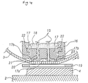
- FIG. 14 illustrates such a print head of an impact dot printer therein disclosed and comprises injecting a lubricant 18 of appropriate viscosity at the back of a front end guide 17 for preventing infiltration of fine particles of ink, ink ribbon scraps, print medium dust, etc., from guide holes 21 in the front end guide 17.
- the infiltration of such particles impairs slidability of print wires 15 and encourages wear of the print wires 15 with respect to the guide holes 21.
- an ink ribbon 3 comes in direct contact with the tips of the wires 15.
- the ribbon 3 keeps a close distance from a surface 17a of the front end guide 17 with a projecting amount of about 0.01 mm from the surface 17a, which is the distance kept when in a standby position.
- the lubricant 18 seeps through the guide holes 21 and through the clearances between the front end guide 17 and a nose 16 by the action of specific gravity.
- the lubricant 18 is transferred onto the ink ribbon 3, and the transferred lubricant 18 causes some ink component to be lost in a lubricant transferred portion 110.
- the conventional examples have encountered problems of elevated cost, because a strict control over the viscosity and amount of the lubricant 18 which must be effected when injecting the lubricant 18 at the back of the front end guide 17 of the head 6 even if the head 6 is mounted upright. Further, when mounting the head 6 facedown, sometimes lubricant is not injected at the back of the front end guide 17 so as to prevent defective printing. However, there have been noticeable losses in reliability and durability, such as printing quality impairment, due not only to wear of the guide holes 21 of the front end guide 17 but also to an increase in sliding resistance of the wires due to ink, paper dust, and ribbon scraps infiltrating into the guide holes 21, and then picking up of the ribbon by the wires.
- an object of the present invention is to provide an impact dot printer which ensures not only stable printing quality but also excellent reliability and durability irrespective of the mounting direction of the head.
- an impact dot printer that includes: a plurality of printer wires; a front end guide having guide holes for guiding the print wires to predetermined print positions; a guide holding member for holding the front end guide.
- Such an impact dot printer receives a lubricant in a portion behind the front end guide and performs the printing operation by biasing an ink ribbon located between the front end guide and a print sheet while projecting the print wires toward the print sheet at appropriate timings.
- projections are provided on a surface of the front end guide, the surface being on the wire projecting side, and these projections form a clearance between the surfaces of the front end guide and the ink ribbon.
- a means for preventing seepage of the lubricant through clearances between the front end guide and the guide holding member is also provided.
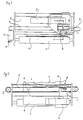
- Figure 1 is a schematic front view showing mechanical portions of an impact dot printer
- Figure 2 is a schematic top view thereof.
- This impact dot printer prints dots using a head 6 that is carried on a carriage 1 supported so as to be movable in the direction of right and left.
- the dots are printed on a print sheet 4 arranged between a platen 2 and an ink ribbon 3 with the head 6 moving on the carriage 1 in the right and left direction, so that the desired characters, graphics, and the like can be printed.
- a connector 7 is carried on a plate 5 and are connected to each other by a flexible print cable 8 for enabling a head drive circuit and the head 6 to be electrically jointed.
- a photocoupler 9 provided on the plate 5 has the function of detecting a home position of the carriage 1 by sensing the presence/absence of a fin 10 arranged on the carriage 1.
- the carriage 1 shuttles horizontally as viewed in Figures 1 and 2 through use of a drive belt 12 and a carriage drive motor 11.
- An encoder 13 mounted on the carriage drive motor 11 generates a signal for detecting the position of the carriage 1, from which signal a reference print timing signal is generated.
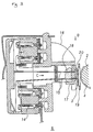
- FIG 3 is a cross section of a print mechanism according to a first embodiment of the present invention.
- the cross section being taken along a line A-A shown in Figure 1.
- Electromagnets 14 are energised at appropriate timings, and the electromagnetic attracting force F thereby generated causes wires 15 to project in the direction indicated by an arrow C.
- Each wire 15 is supported by one or more guides; particularly, the tip of the wire 15 is supported by a front end guide 17 held by a nose 16 serving as a guide holding member.
- a lubricant 18 is injected into and stays in a portion behind the front end guide 17.
- the lubricant 18 may include, e.g., napthene oil, paraffin oil and olefin oil.
- the ink ribbon 3 In the direction of projection of the wires 15, are the ink ribbon 3 and print sheet 4.
- the print sheet 4 abuts against the platen 2 that serves as a resilient end stopper.
- a ribbon mask 19 having an opening larger than an area in which the print wires 15 are arranged.
- This ribbon mask 19 has the function of preventing the print sheet 4 from being stained due to the ink ribbon 3 coming in direct contact with the print sheet 4.
- the projected wires 15 strike with a given impact onto the print sheet surface through the ink ribbon 3, thereby forming ink marks on the print sheet surface.
- the ink ribbon 3 is rewound by a ribbon rewinder (not shown) in a direction indicated by an arrow D in Figure 4 and is in contact with the tips of the print wires 15 of the head 6 under a certain tension.
- Figure 4 is a partial view mainly showing the front end guide 17 as viewed from a direction indicated by an arrow B in Figure 3
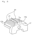
- Figure 5 is a perspective view showing the front end guide 17.
- the front end guide 17 is secured with the entire parts of side surfaces 17b thereof press-fitted into grooves 22 provided in the nose 16 so as to come in tight contact with one another.
- projections 20 are provided on a surface 17a on the wire projecting side of the front end guide 17. As a result of these projections 20, a predetermined distance can be provided between the ink ribbon 3 and the surface 17a of the front end guide 17.
- the lubricant 18 is injected in the portion behind the front end guide 17 but does leak out on the wire projecting side surface 17a of the front end guide 17 through the guide holes 21. However, the lubricant 18 does not flow out through clearances between the side surfaces 17b and the grooves 22 since the front end guide side surfaces 17b and the grooves 22 are in tight contact with each other. The lubricant 18 seeping from the guide holes 21 no longer comes in direct contact with the ink ribbon 3 because of the projections 20. Thus, the lubricant 18 is not transferred onto the ink ribbon 3, thereby not causing defective printing such as shown by portions "a" in Figure 17.
- each print wire 15 is set to 0.2 mm; the distance d o between the two lines of guide holes 21 of the front end guide 17 is set to 0.08467 mm (1/30 inches); and the amount of projection of each print wire 15 from the front guide surface 17a in a standby position is set to 0.01 mm.
- each projection 20 is set to a value either equal to the amount of projection of the print wire 15 from the front guide surface 17a in the standby position, i.e., 0.01 mm, or more and a distance L between the projection and an edge point of the guide hole 21 is set to 1.5 mm or less, which is 150 times the amount of projection of the print wire 15 from the front end guide surface 17a in the standby position or less, then the lubricant 18 is not likely to be transferred onto the ink ribbon 3: even when the ink ribbon 3 is slackened which sometimes happens under normal printing conditions.
- Figure 6 shows a second embodiment of the present invention in which the projections 20 are formed equidistantly from the guide holes 21.
- each projection 20 has arcuate recesses on the side confronting the guide holes 21.
- the same dimensions of H and L with respect to the print wire projection apply.
- the second embodiment can attain the same advantages as the first embodiment.
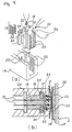
- Figure 7(a) is a front view in the vicinity of a front end guide according to a third embodiment of the present invention; and Figure 7(b) is a bottom view thereof.
- Figure 8(a) is an exploded perspective view of the third embodiment
- Figure 8(b) is a diagram showing a section taken along a line E-E shown in Figure 7(a).
- a plurality of print wires 15 are slidably held by guide holes 21,23 whose diameters are slightly larger than that of each wire 15.
- the guide holes 21,23 are arranged on a front end guide 17 and an intermediate guide 24, respectively.
- the intermediate guide 24 is held by intermediate guide grooves 25 provided in a nose 16.
- the front end guide 17 has a mounting groove 26 in a side surface thereof, and a ring-like elastic member 27 is attached to this mounting groove 26.
- An O ring is used as the elastic member 27 in this embodiment.
- the front end guide 17 is inserted into front end guide grooves 28 in the nose 16 and firmly secured to the nose 16 by causing pins 29 of the nose 16 to be fitted into fusing holes 30 in the front end guide 17 by fusing.
- the pins 29 may be fused with the holes 30 by the application of ultrasonic vibration to the pins, so that they melt due to the heat generated by the vibration and then set. Alternatively a soldering iron can be used to generate the heat.
- Grooves 31 are provided at portions in the nose 16 so that the elastic member 26 can be secured surely, such portions abutting against the elastic member 26.
- the front end guide 17 has an injection hole 32 that allows a lubricant 18 of appropriate viscosity to be injected therefrom after the front end guide 17, the intermediate guide 24, and the print wires 15 have been assembled. The injected lubricant 18 is kept in a portion surrounded by the front end guide 17, the intermediate guide 24, and the nose 16.
- Figure 9(a) is an exploded perspective view of a fourth embodiment of the present invention
- Figure 9(b) is a sectional view thereof which is similar to the sectional view taken along the line E-E shown in Figure 7(a).
- the fourth embodiment has a general construction similar to that of the third embodiment, and so only those points which are different from the third embodiment will be described.
- the front end guide 17 has grooves 34 in side surfaces thereof, whereas the nose 16 has grooves 35 at positions confronting the grooves 34.
- a shield member 33 is injected into a space between the grooves 34 and 35. While silicon rubber may be used as the shield member 33 in this embodiment, the material is not limited thereto.
- An adhesive or the like may be used as long as such adhesive has a shielding property.
- FIG 10(a) is an exploded perspective view of a fifth embodiment of the invention, embodiment of the invention, and Figure 10(b) is a sectional view thereof which is similar to the sectional view taken along the line E-E shown in Figure 7(a).
- the fifth embodiment has a general construction similar to that of the third embodiment and so only those points which are different from the third embodiment will be described.
- the front end guide 17 has a plurality of projections 36 on each of front end side surfaces 17c of portions that are inserted into grooves 28 of the nose 16.
- a length d1 from a surface 17d to the tip of each projection 36 is designed to be slightly larger than a width d2 of the groove 28, the surface 17d coming into contact with the groove 28 and being opposite to the surface 17c having the projections 36.
- Figure 11(a) is an exploded perspective view of a sixth embodiment of the invention, and Figure 11(b) is a sectional view thereof which is similar to the sectional view taken along the line E-E shown in Figure 7(a).
- Figure 12(a) is a top view of the front end guide 17 of the sixth embodiment;
- Figure 12(b) is a back view thereof;
- Figure 12(c) is a side view thereof.
- the sixth embodiment has a general construction similar to that of the third embodiment and so only those points which are different from the third embodiment will be described.
- the front end guide 17 will be described with reference to Figure 12.
- the front end guide 17 has walls 37 in a direction perpendicular to the front end surface 17a, the walls 37 being tapered toward the back of the front end guide 17.
- the front end guide 17 is made of resin, and the walls 37 can be elastically deformed horizontally. To reduce the rigidity in the horizontal direction, the walls 37 have cut portions 39 confronting a bottom portion 38. The walls 37 have chamfered portions 43 in a direction G of inserting the front end guide 17.
- the front end guide 17 has a pin 40 in the insertion direction G, whereas fusing holes 30 and an injection hole 32 are provided in the bottom portion 38 thereof.
- the nose 16 has a throughhole 41 in the front end guide 17 insertion direction G.
- the pin 40 of the front end guide 17 is fitted into the throughhole 41 when the front end guide 17 has been inserted into the nose 16.
- the nose 16 also has pins 29, which are fitted into the fusing holes 30 at the time of inserting the front end guide 17.
- Continuously extending projected portions 42 are formed on the inside walls of the nose 16 where the front end guide 17 are to be inserted.
- a distance d3 between the confronting projected portions 42 is designed to be slightly smaller than a distance d4 between the outer surfaces of the walls 37 of the front end guide 17.
- the walls 37 elastically deform inwardly at the time of inserting the front end guide 17, causing the walls 37 to come in intimate contact with the continuously extending projected portions 42. At this point, the chamfered portions 43 of the walls 37 allow smooth insertion.
- the front end guide 17 is held by a tool (not shown) so that the front end surface 17a of the front end guide 17 and a front end surface 16a of the nose 16 stay coplanar, and under this condition the pin 40 and the throughhole 41 as well as the pins 29 and the fusing holes 30 are fused and thereby positioned and fixed. Since the walls 37 are formed in the direction perpendicular to the front end surface 17a, the front end surfaces 17a and 16a can be made coplanar without being restricted by the walls 37. Although clearances are formed by the cut portions 39 between the walls 37 and the bottom portion 38, the surfaces that come in intimate contact cover substantially the same area as an area into which the lubricant 18 is injected.
- Figure 13(a) is an exploded perspective view of a seventh embodiment of the present invention
- Figure 13(b) is a sectional view thereof which is similar to the sectional view taken along the line E-E shown in Figure 7(a).
- the seventh embodiment has a general construction similar to that of the third embodiment and so only those points different from the first embodiment will be described.
- the front end guide 17 has projections 44 continuously extending on both side surfaces 17e thereof. A distance d5 between these projections is designed to be slightly greater than a distance d6 of the front end guide accommodating portion of the nose 16. Thus, the outer surface of each projection 44 gets slightly deformed plastically at the time the front end guide 17 is inserted to thereby come in intimate contact with the nose 16.
- the invention is characterised as providing projections on the print wire projecting side surface of a front end guide in an impact dot printer, such impact dot printer including a plurality of print wires and the front end guide having holes for guiding the print wires to print positions, and a guide holding member for holding the front end guide, accommodating a lubricant in the guide holes of the front end guide, locating an ink ribbon between the front end guide and a print sheet, and printing dots by projecting the wires onto the print sheet at appropriate timings.
- the impact dot printer of the invention is free from defective printing in which no dot marks are produced out of the operation of projecting the print wires onto such lubricant transferred portion.
- the means for preventing seepage of the lubricant through clearances between the front end guide and the guide holding member contributes to preventing outflow of the lubricant from any part except for the guide holes.
Landscapes
- Impact Printers (AREA)
- Impression-Transfer Materials And Handling Thereof (AREA)
Applications Claiming Priority (6)
| Application Number | Priority Date | Filing Date | Title |
|---|---|---|---|
| JP218414/91 | 1991-08-29 | ||
| JP218417/91 | 1991-08-29 | ||
| JP21841791 | 1991-08-29 | ||
| JP21841491 | 1991-08-29 | ||
| JP4164947A JP3024663B2 (ja) | 1991-08-29 | 1992-06-23 | インパクトドットプリンタ |
| JP164947/92 | 1992-06-23 |
Publications (2)
| Publication Number | Publication Date |
|---|---|
| EP0529652A1 true EP0529652A1 (de) | 1993-03-03 |
| EP0529652B1 EP0529652B1 (de) | 1995-11-29 |
Family
ID=27322410
Family Applications (1)
| Application Number | Title | Priority Date | Filing Date |
|---|---|---|---|
| EP92114737A Expired - Lifetime EP0529652B1 (de) | 1991-08-29 | 1992-08-28 | Schlagpunktdrucker |
Country Status (5)
| Country | Link |
|---|---|
| US (1) | US5540508A (de) |
| EP (1) | EP0529652B1 (de) |
| JP (1) | JP3024663B2 (de) |
| DE (1) | DE69206355T2 (de) |
| HK (1) | HK109096A (de) |
Cited By (1)
| Publication number | Priority date | Publication date | Assignee | Title |
|---|---|---|---|---|
| EP0639464A3 (de) * | 1993-08-19 | 1996-01-31 | Oki Electric Ind Co Ltd | Punkdruckkopf und Verfahren für die Drucksteuerung. |
Families Citing this family (3)
| Publication number | Priority date | Publication date | Assignee | Title |
|---|---|---|---|---|
| US6945645B2 (en) | 2002-05-06 | 2005-09-20 | Hewlett-Packard Development Company, Lp. | Method and apparatus for scoring media |
| JP4467894B2 (ja) * | 2003-02-10 | 2010-05-26 | シチズンホールディングス株式会社 | 印字ヘッド |
| JP5759837B2 (ja) * | 2011-09-06 | 2015-08-05 | 東芝テック株式会社 | ドットヘッド及びドットプリンタ |
Citations (4)
| Publication number | Priority date | Publication date | Assignee | Title |
|---|---|---|---|---|
| EP0067542A1 (de) * | 1981-06-04 | 1982-12-22 | Tokyo Electric Co. Ltd. | Druckkopf für Punktschreiber |
| EP0296637A2 (de) * | 1987-06-25 | 1988-12-28 | Nec Corporation | Lager für Matrixdruckkopf |
| EP0372557A2 (de) * | 1988-12-09 | 1990-06-13 | Seiko Epson Corporation | Punktnadeldrucker mit Drucknadelantrieb und Verfahren zu seiner Herstellung |
| EP0461642A1 (de) * | 1990-06-15 | 1991-12-18 | Seiko Epson Corporation | Punkt-Schlag-Druckknopf und Herstellungsverfahren dafür |
Family Cites Families (10)
| Publication number | Priority date | Publication date | Assignee | Title |
|---|---|---|---|---|
| FR2152187A5 (de) * | 1971-09-09 | 1973-04-20 | Anker Werke Ag | |
| US3987883A (en) * | 1975-04-17 | 1976-10-26 | International Business Machines Corporation | Ribbon lifting mechanism for a wire matrix printer |
| JPS58166065A (ja) * | 1982-03-26 | 1983-10-01 | Fujitsu Ltd | プリントヘツド |
| JPS59199266A (ja) * | 1983-04-28 | 1984-11-12 | Fujitsu Ltd | ワイヤドツトプリンタの印字ヘツド |
| US4506999A (en) * | 1983-07-12 | 1985-03-26 | Telesis Controls Corporation | Program controlled pin matrix embossing apparatus |
| US4613241A (en) * | 1984-01-05 | 1986-09-23 | Nec Corporation | Printing mechanism for dot matrix printers |
| JPS60228166A (ja) * | 1984-04-26 | 1985-11-13 | Fujitsu Ltd | 印字ヘツド |
| DE3679517D1 (de) * | 1985-12-05 | 1991-07-04 | Ncr Co | Drahtpunktdruckkopf. |
| JPH02528A (ja) * | 1989-01-25 | 1990-01-05 | Seiko Epson Corp | ワイヤ式ドットプリンタ用ヘッド |
| JPH037351A (ja) * | 1989-06-05 | 1991-01-14 | Seiko Epson Corp | インパクトドットヘッド |
-
1992
- 1992-06-23 JP JP4164947A patent/JP3024663B2/ja not_active Expired - Fee Related
- 1992-08-28 DE DE69206355T patent/DE69206355T2/de not_active Expired - Lifetime
- 1992-08-28 EP EP92114737A patent/EP0529652B1/de not_active Expired - Lifetime
-
1994
- 1994-11-16 US US08/341,280 patent/US5540508A/en not_active Expired - Lifetime
-
1996
- 1996-06-27 HK HK109096A patent/HK109096A/en not_active IP Right Cessation
Patent Citations (4)
| Publication number | Priority date | Publication date | Assignee | Title |
|---|---|---|---|---|
| EP0067542A1 (de) * | 1981-06-04 | 1982-12-22 | Tokyo Electric Co. Ltd. | Druckkopf für Punktschreiber |
| EP0296637A2 (de) * | 1987-06-25 | 1988-12-28 | Nec Corporation | Lager für Matrixdruckkopf |
| EP0372557A2 (de) * | 1988-12-09 | 1990-06-13 | Seiko Epson Corporation | Punktnadeldrucker mit Drucknadelantrieb und Verfahren zu seiner Herstellung |
| EP0461642A1 (de) * | 1990-06-15 | 1991-12-18 | Seiko Epson Corporation | Punkt-Schlag-Druckknopf und Herstellungsverfahren dafür |
Cited By (1)
| Publication number | Priority date | Publication date | Assignee | Title |
|---|---|---|---|---|
| EP0639464A3 (de) * | 1993-08-19 | 1996-01-31 | Oki Electric Ind Co Ltd | Punkdruckkopf und Verfahren für die Drucksteuerung. |
Also Published As
| Publication number | Publication date |
|---|---|
| HK109096A (en) | 1996-07-05 |
| EP0529652B1 (de) | 1995-11-29 |
| JPH05177846A (ja) | 1993-07-20 |
| DE69206355T2 (de) | 1996-05-09 |
| DE69206355D1 (de) | 1996-01-11 |
| US5540508A (en) | 1996-07-30 |
| JP3024663B2 (ja) | 2000-03-21 |
Similar Documents
| Publication | Publication Date | Title |
|---|---|---|
| EP1872954B1 (de) | Anschlagdruckkopf | |
| EP0529652B1 (de) | Schlagpunktdrucker | |
| US20050201797A1 (en) | Wire dot printer head and wire dot printer | |
| US4109776A (en) | Apparatus for marking an information carrying medium | |
| EP0128558B1 (de) | Farbpunktdrucker | |
| JP2976643B2 (ja) | インパクトドットプリンタ | |
| JPS6042062A (ja) | ワイヤドツトヘツド | |
| JP2000141698A (ja) | インクジェットプリンタ | |
| JP3329121B2 (ja) | 印字ヘッド | |
| JP3083971B2 (ja) | インクリボンカセット | |
| JPH10305628A (ja) | ラインサーマルプリンタ | |
| US5340222A (en) | Ink ribbon with wire lubricant in a wire impact printer | |
| JPS58215364A (ja) | 印字ヘツド | |
| JPH06115105A (ja) | インパクトドットヘッド | |
| JPH06115111A (ja) | インパクトドットヘッド | |
| JPS58217373A (ja) | 印字ヘツド | |
| JPS60107358A (ja) | 印字ヘツド | |
| JPS59103781A (ja) | シリアルプリンタ | |
| JPS58215363A (ja) | 印字ヘツド | |
| JPH06183037A (ja) | ドットプリンタヘッド | |
| JPH0436863B2 (de) | ||
| JPS6250072A (ja) | ワイヤドツトヘツド | |
| JPH0544540U (ja) | インパクトドツトヘツド | |
| JPS612572A (ja) | ドツトプリンタ印字ヘツド用可動装置 | |
| JPH1029326A (ja) | 印字ヘッド |
Legal Events
| Date | Code | Title | Description |
|---|---|---|---|
| PUAI | Public reference made under article 153(3) epc to a published international application that has entered the european phase |
Free format text: ORIGINAL CODE: 0009012 |
|
| AK | Designated contracting states |
Kind code of ref document: A1 Designated state(s): DE FR GB |
|
| 17P | Request for examination filed |
Effective date: 19930726 |
|
| 17Q | First examination report despatched |
Effective date: 19941214 |
|
| GRAA | (expected) grant |
Free format text: ORIGINAL CODE: 0009210 |
|
| AK | Designated contracting states |
Kind code of ref document: B1 Designated state(s): DE FR GB |
|
| REF | Corresponds to: |
Ref document number: 69206355 Country of ref document: DE Date of ref document: 19960111 |
|
| ET | Fr: translation filed | ||
| PLBE | No opposition filed within time limit |
Free format text: ORIGINAL CODE: 0009261 |
|
| 26N | No opposition filed | ||
| REG | Reference to a national code |
Ref country code: GB Ref legal event code: IF02 |
|
| PGFP | Annual fee paid to national office [announced via postgrant information from national office to epo] |
Ref country code: FR Payment date: 20090814 Year of fee payment: 18 |
|
| PGFP | Annual fee paid to national office [announced via postgrant information from national office to epo] |
Ref country code: GB Payment date: 20090826 Year of fee payment: 18 Ref country code: DE Payment date: 20090821 Year of fee payment: 18 |
|
| GBPC | Gb: european patent ceased through non-payment of renewal fee |
Effective date: 20100828 |
|
| REG | Reference to a national code |
Ref country code: FR Ref legal event code: ST Effective date: 20110502 |
|
| REG | Reference to a national code |
Ref country code: DE Ref legal event code: R119 Ref document number: 69206355 Country of ref document: DE Effective date: 20110301 |
|
| PG25 | Lapsed in a contracting state [announced via postgrant information from national office to epo] |
Ref country code: FR Free format text: LAPSE BECAUSE OF NON-PAYMENT OF DUE FEES Effective date: 20100831 Ref country code: DE Free format text: LAPSE BECAUSE OF NON-PAYMENT OF DUE FEES Effective date: 20110301 |
|
| PG25 | Lapsed in a contracting state [announced via postgrant information from national office to epo] |
Ref country code: GB Free format text: LAPSE BECAUSE OF NON-PAYMENT OF DUE FEES Effective date: 20100828 |