EP0529807A2 - Vis sans fin de développement pour l'utilisation dans un appareil d'impression électrophotographique - Google Patents
Vis sans fin de développement pour l'utilisation dans un appareil d'impression électrophotographique Download PDFInfo
- Publication number
- EP0529807A2 EP0529807A2 EP92306871A EP92306871A EP0529807A2 EP 0529807 A2 EP0529807 A2 EP 0529807A2 EP 92306871 A EP92306871 A EP 92306871A EP 92306871 A EP92306871 A EP 92306871A EP 0529807 A2 EP0529807 A2 EP 0529807A2
- Authority
- EP
- European Patent Office
- Prior art keywords
- flight
- developer
- auger
- pitch distance
- shaft
- Prior art date
- Legal status (The legal status is an assumption and is not a legal conclusion. Google has not performed a legal analysis and makes no representation as to the accuracy of the status listed.)
- Granted
Links
Images


Classifications
-
- G—PHYSICS
- G03—PHOTOGRAPHY; CINEMATOGRAPHY; ANALOGOUS TECHNIQUES USING WAVES OTHER THAN OPTICAL WAVES; ELECTROGRAPHY; HOLOGRAPHY
- G03G—ELECTROGRAPHY; ELECTROPHOTOGRAPHY; MAGNETOGRAPHY
- G03G15/00—Apparatus for electrographic processes using a charge pattern
- G03G15/06—Apparatus for electrographic processes using a charge pattern for developing
- G03G15/08—Apparatus for electrographic processes using a charge pattern for developing using a solid developer, e.g. powder developer
- G03G15/0822—Arrangements for preparing, mixing, supplying or dispensing developer
-
- G—PHYSICS
- G03—PHOTOGRAPHY; CINEMATOGRAPHY; ANALOGOUS TECHNIQUES USING WAVES OTHER THAN OPTICAL WAVES; ELECTROGRAPHY; HOLOGRAPHY
- G03G—ELECTROGRAPHY; ELECTROPHOTOGRAPHY; MAGNETOGRAPHY
- G03G2215/00—Apparatus for electrophotographic processes
- G03G2215/08—Details of powder developing device not concerning the development directly
- G03G2215/0802—Arrangements for agitating or circulating developer material
- G03G2215/0816—Agitator type
- G03G2215/0819—Agitator type two or more agitators
- G03G2215/0822—Agitator type two or more agitators with wall or blade between agitators
-
- G—PHYSICS
- G03—PHOTOGRAPHY; CINEMATOGRAPHY; ANALOGOUS TECHNIQUES USING WAVES OTHER THAN OPTICAL WAVES; ELECTROGRAPHY; HOLOGRAPHY
- G03G—ELECTROGRAPHY; ELECTROPHOTOGRAPHY; MAGNETOGRAPHY
- G03G2215/00—Apparatus for electrophotographic processes
- G03G2215/08—Details of powder developing device not concerning the development directly
- G03G2215/0802—Arrangements for agitating or circulating developer material
- G03G2215/0816—Agitator type
- G03G2215/0827—Augers
- G03G2215/0833—Augers with varying pitch on one shaft
Definitions
- This invention relates generally to an electrophotographic printing machine adapted to produce highlight color copies, and more particularly concerns a developer auger which is used in a development system of an electrophotographic printing machine.
- the features of the present invention may be used in the printing arts and, more particularly, in electrophotographic printing.
- a photoconductive surface is charged to a substantially uniform potential.
- the photoconductive surface is selectively exposed to record an electrostatic latent image corresponding to the informational areas of an original document being reproduced.
- a developer material is transported into contact with the electrostatic latent image.
- the developer material comprises toner particles adhering triboelectrically to carrier granules.
- the toner particles are attracted from the carrier granules of the developer material onto the latent image.
- the resultant toner particle image is then transferred from the photoconductive surface to a copy sheet and permanently affixed thereto.
- US-A-4,682,874 discloses an apparatus which detects when particles being dispensed into a development system have been depleted and provides a display of that condition.
- the apparatus advances particles from a store thereof to the development system.
- a detector associated with the particle advancer, senses the exhaustion of particles being advanced to the development system.
- the development system shown herein includes a pair of augers.
- US-A-4,813,531 describes a developer transport apparatus which includes a rotatable auger for transporting developer along its length from a developer entry to a developer delivery end.
- US-A-4,937,625 discloses a developing device for developing a toner image on a cylindrical electrophotographic photoreceptor.
- the device includes a toner container which extends perpendicularly to the direction of the photoreceptor and a toner transporting device for moving the toner supplied from the container in the direction of the axis of the photoreceptor.
- the toner transporting device includes a pair of screws, each having a stirrer plate positioned thereon to redirect the flow of toner.
- U.S. Patent Application Serial No. 07/708,429 filed 31 May 1991 describes an apparatus which develops an electrostatic latent image with toner particles.
- the toner particles being used to develop the latent image are reclaimed and unused.
- An auger transports the unused and reclaimed toner particles to a discharge region where the toner particles are dispensed into the sump of the developer housing.
- the auger has a greater particle advancing capacity, in the region adjacent the container storing reclaimed toner particles and extending to the housing storing unused toner particles, than in the region adjacent the housing storing unused toner particles.
- a developer auger possessing a plurality of flight segments for use in a development system of an electrophotographic printing machine.
- the developer auger comprises a shaft and a first flight portion, mounted on the shaft, wherein the first flight portion comprises at least two flight segments which define a first pitch distance.
- the developer auger further comprises a second flight portion, mounted on the shaft and positioned adjacent the first flight portion, wherein the second flight portion comprises at least two flight segments which define a second pitch distance which is greater than the first pitch distance.
- an electrophotographic printing machine of the type having a development system which transports developer material for subsequent image development that includes a developer auger possessing a plurality of flight segments.
- the printing machine comprises a shaft and a first flight portion, mounted on the shaft, wherein the first flight portion comprises at least two flight segments which define a first pitch distance.
- the printing machine further comprises a second flight portion, mounted on the shaft and positioned adjacent the first flight portion, wherein the second flight portion comprises at least two flight segments which define a second pitch distance which is greater than the first pitch distance.
- FIG. 1 schematically depicts the various components of an electrophotographic printing machine incorporating the features of the present invention therein. It will become evident from the following discussion that the present invention is equally well suited for use in a wide variety of printing machines, and is not necessarily limited in its application to the particular system shown herein.
- a corona discharging device such as a scorotron, corotron or dicorotron indicated by the reference numeral 24, charges the belt 10 to a selectively high uniform positive or negative potential. Preferably charging is negative. Any suitable control, well known in the art, may be employed for controlling corona discharge device 24.
- the photoconductive surface which is initially charged to a relatively high charge potential (about 900 volts), is selectively discharged to a midway potential (about 500 volts) in the background (white) image areas and to near zero or ground potential in the highlight (i.e. color other than black) color parts of the image.
- a magnetic brush development system advances developer material into contact with the electrostatic latent images.
- the development system 30 comprises first and second magnetic brush developer units 32 and 34, respectively.
- each of the developer units includes a pair of magnetic brush developer rollers mounted in a housing.
- developer unit 32 contains a pair of magnetic brush rollers 35 and 36
- developer unit 34 contains a pair of magnetic brush rollers 37 and 38.
- Each pair of rollers advances its respective developer material into contact with the latent image.
- each of the developer units 32 and 34 include a pick-off roller 44 and 46, respectively, for acquiring carrier granules which were improperly transferred to the latent image and returning such carrier granules to its respective development unit.
- Developer unit 32 further includes three developer augers 50, 51 and 52 while developer unit 34 further includes three developer augers 53, 54 and 55. Appropriate developer biasing is accomplished via power supplies 41 and 43 electrically connected to respective developer units 32 and 34.
- Color discrimination in the development of the electrostatic latent image is achieved by moving the latent image recorded on the photoconductive surface past developer units 32 and 34 in a single pass with the magnetic brush rollers 35, 36, 37 and 38 electrically biased to voltages which are offset from the background voltage, the direction of offset depending on the polarity of toner in the housing.
- the first developer unit 32 in the direction of movement of belt 10 as indicated by arrow 16, develops the discharged image areas of the photoconductive surface.
- This developer unit contains red developer material (not shown) having triboelectric properties such that the red toner is driven to the discharged image areas of the latent image by the electrostatic field between the photoconductive surface and the electrically biased developer rollers in the first developer unit.
- the second developer unit 34 in the direction of movement of belt 10 as indicated by arrow 16, develops the highly charged image areas of the latent image.
- This developer unit contains black developer material (not shown) having a triboelectric charge such that the black toner is urged towards the highly charged areas of the latent image by the electrostatic field existing between the photoconductive surface and the electrically biased developer rollers in the second developer unit.
- a sheet of support material 58 is moved into contact with the toner image at a transfer station D.
- the sheet of support material is advanced to transfer station D by a conventional sheet feeding apparatus (not shown).
- the sheet feeding apparatus includes a feed roller contacting the uppermost sheet of a stack of copy sheets. The feed roller rotates so as to advance the uppermost sheet from the stack into a chute which directs the advancing sheet of support material into contact with the photoconductive surface of belt 10 in a timed sequence so that the toner particle image developed thereon contacts the advancing sheet of support material at transfer station D.
- Transfer station D includes a corona generating device 60 which sprays ions of a suitable polarity onto the backside of sheet 58. This attracts substantially simultaneously the black and non-black portions of the toner particle image from belt 10 to sheet 58. After transfer, the sheet continues to move, in the direction of arrow 62, onto a conveyor (not shown) which advances the sheet to a fusing station E.
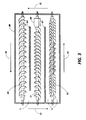
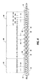
- Providing a developer auger which possesses adjacent flight portions each having a different pitch distance between adjacent flight segments thereof along the length of the auger functions to alter the rate of speed at which the developer material is propelled within a developer housing. For example, the rate of speed at which the developer material would be propelled by a flight portion having a pitch distance of D1 is less than the rate of speed at which the developer material would be propelled by another flight portion having a pitch distance of D2.
- a developer auger possessing a plurality of flight segments for use in a development system of an electrophotographic printing machine.
- the developer auger comprises a shaft and a first flight portion, spirally mounted on the shaft, wherein the first flight portion comprises at least two flight segments which define a first pitch distance.
- the developer auger further comprises a second flight portion, spirally mounted on the shaft and positioned adjacent the first flight portion, wherein the second flight portion comprises at least two flight segments which define a second pitch distance which is greater than the first pitch distance.
Landscapes
- Physics & Mathematics (AREA)
- General Physics & Mathematics (AREA)
- Dry Development In Electrophotography (AREA)
Applications Claiming Priority (2)
| Application Number | Priority Date | Filing Date | Title |
|---|---|---|---|
| US07/749,850 US5204721A (en) | 1991-08-26 | 1991-08-26 | Developer auger for use in an electrophotographic printing machine |
| US749850 | 1991-08-26 |
Publications (3)
| Publication Number | Publication Date |
|---|---|
| EP0529807A2 true EP0529807A2 (fr) | 1993-03-03 |
| EP0529807A3 EP0529807A3 (en) | 1993-05-12 |
| EP0529807B1 EP0529807B1 (fr) | 1996-10-02 |
Family
ID=25015475
Family Applications (1)
| Application Number | Title | Priority Date | Filing Date |
|---|---|---|---|
| EP92306871A Expired - Lifetime EP0529807B1 (fr) | 1991-08-26 | 1992-07-28 | Vis sans fin de développement pour l'utilisation dans un appareil d'impression électrophotographique |
Country Status (5)
| Country | Link |
|---|---|
| US (1) | US5204721A (fr) |
| EP (1) | EP0529807B1 (fr) |
| JP (1) | JP3323243B2 (fr) |
| CA (1) | CA2076764C (fr) |
| DE (1) | DE69214236T2 (fr) |
Cited By (4)
| Publication number | Priority date | Publication date | Assignee | Title |
|---|---|---|---|---|
| EP0689105A3 (fr) * | 1994-06-21 | 1997-05-21 | Mita Industrial Co Ltd | Dispositif pour mélanger et transporteur du développateur |
| EP0658825A3 (fr) * | 1993-12-17 | 1998-02-04 | Mita Industrial Co., Ltd. | Dispositif de développement d'images électrostatiques latents |
| EP0816938A3 (fr) * | 1996-07-04 | 1999-04-07 | Mita Industrial Co. Ltd. | Dispositif de transport et cartouche de toner avec le dispositif de transport |
| EP0967530A3 (fr) * | 1994-01-14 | 2000-11-22 | Kyocera Mita Corporation | Appareil de formation d'image |
Families Citing this family (15)
| Publication number | Priority date | Publication date | Assignee | Title |
|---|---|---|---|---|
| JP3364632B2 (ja) * | 1994-11-08 | 2003-01-08 | 株式会社リコー | トナー補給装置 |
| US5937252A (en) * | 1998-01-07 | 1999-08-10 | Xerox Corporation | Trickle port between two augers in a developer housing |
| US6266504B1 (en) * | 2000-02-10 | 2001-07-24 | Toshiba Tec Kabushiki Kaisha | Developing apparatus and image forming apparatus |
| US6546225B2 (en) | 2001-02-21 | 2003-04-08 | Lexmark International, Inc. | Auger for dispensing waste toner |
| US7035573B2 (en) * | 2002-09-24 | 2006-04-25 | Canon Kabushiki Kaisha | Developing apparatus having developer carrying screw with a plurality of inclination angles |
| US6978106B2 (en) * | 2002-12-12 | 2005-12-20 | Canon Kabushiki Kaisha | Developing apparatus having modified developer carrying capability |
| JP2005156639A (ja) * | 2003-11-20 | 2005-06-16 | Ricoh Printing Systems Ltd | 現像装置及びこれを用いた静電記録装置 |
| JP4615921B2 (ja) | 2003-11-21 | 2011-01-19 | 株式会社東芝 | 画像形成装置 |
| US7667874B2 (en) * | 2005-07-06 | 2010-02-23 | Xerox Corporation | Method and system for improving print quality |
| US7426361B2 (en) * | 2005-09-01 | 2008-09-16 | Eastman Kodak Company | Developer mixing apparatus having four ribbon blenders |
| KR100699256B1 (ko) * | 2005-09-29 | 2007-03-28 | 삼성전자주식회사 | 화상형성장치 및 현상제 반송장치 |
| US7313348B2 (en) * | 2005-10-31 | 2007-12-25 | Xerox Corporation | Xerographic developer unit having variable pitch auger |
| US20080181672A1 (en) * | 2007-01-25 | 2008-07-31 | Kabushiki Kaisha Toshiba | Development apparatus and image forming apparatus |
| JP5335540B2 (ja) * | 2009-04-28 | 2013-11-06 | キヤノン株式会社 | 現像剤補給装置 |
| JP6079242B2 (ja) * | 2013-01-09 | 2017-02-15 | 富士ゼロックス株式会社 | 現像剤撹拌搬送部材、現像装置、及び画像形成装置 |
Family Cites Families (11)
| Publication number | Priority date | Publication date | Assignee | Title |
|---|---|---|---|---|
| US3271819A (en) * | 1962-02-26 | 1966-09-13 | Nrm Corp | Extruder |
| US4682874A (en) * | 1981-11-19 | 1987-07-28 | Xerox Corporation | Particle level indicator |
| JPS6087364A (ja) * | 1983-10-19 | 1985-05-17 | Toshiba Corp | 現像装置 |
| US4724457A (en) * | 1986-10-23 | 1988-02-09 | Xerox Corporation | Developer unit using three angers in three chambers |
| JP2819530B2 (ja) * | 1987-07-17 | 1998-10-30 | 株式会社リコー | 現像装置 |
| US4937625A (en) * | 1987-08-28 | 1990-06-26 | Sharp Kabushiki Kaisha | Developing device for copier |
| US4813531A (en) * | 1988-03-10 | 1989-03-21 | Xerox Corporation | Developer transport apparatus |
| US5005517A (en) * | 1988-07-06 | 1991-04-09 | Minolta Camera Kabushiki Kaisha | Developing device |
| US4980724A (en) * | 1989-06-15 | 1990-12-25 | Xerox Corporation | Developer material crossmixing apparatus |
| EP0430098B1 (fr) * | 1989-11-29 | 1995-05-03 | Mita Industrial Co., Ltd. | Rouleau d'alimentation pour mélanger une poudre |
| US5166732A (en) * | 1990-09-14 | 1992-11-24 | Mita Industrial Co., Ltd. | Developer agitating method and developer agitating apparatus |
-
1991
- 1991-08-26 US US07/749,850 patent/US5204721A/en not_active Expired - Fee Related
-
1992
- 1992-07-28 EP EP92306871A patent/EP0529807B1/fr not_active Expired - Lifetime
- 1992-07-28 DE DE69214236T patent/DE69214236T2/de not_active Expired - Fee Related
- 1992-08-10 JP JP23427092A patent/JP3323243B2/ja not_active Expired - Fee Related
- 1992-08-25 CA CA002076764A patent/CA2076764C/fr not_active Expired - Fee Related
Cited By (4)
| Publication number | Priority date | Publication date | Assignee | Title |
|---|---|---|---|---|
| EP0658825A3 (fr) * | 1993-12-17 | 1998-02-04 | Mita Industrial Co., Ltd. | Dispositif de développement d'images électrostatiques latents |
| EP0967530A3 (fr) * | 1994-01-14 | 2000-11-22 | Kyocera Mita Corporation | Appareil de formation d'image |
| EP0689105A3 (fr) * | 1994-06-21 | 1997-05-21 | Mita Industrial Co Ltd | Dispositif pour mélanger et transporteur du développateur |
| EP0816938A3 (fr) * | 1996-07-04 | 1999-04-07 | Mita Industrial Co. Ltd. | Dispositif de transport et cartouche de toner avec le dispositif de transport |
Also Published As
| Publication number | Publication date |
|---|---|
| EP0529807A3 (en) | 1993-05-12 |
| EP0529807B1 (fr) | 1996-10-02 |
| JPH05197285A (ja) | 1993-08-06 |
| CA2076764A1 (fr) | 1993-02-27 |
| DE69214236D1 (de) | 1996-11-07 |
| US5204721A (en) | 1993-04-20 |
| CA2076764C (fr) | 1998-10-27 |
| JP3323243B2 (ja) | 2002-09-09 |
| DE69214236T2 (de) | 1997-03-06 |
Similar Documents
| Publication | Publication Date | Title |
|---|---|---|
| EP0529807B1 (fr) | Vis sans fin de développement pour l'utilisation dans un appareil d'impression électrophotographique | |
| EP0426420B1 (fr) | Appareil de développement | |
| US5499090A (en) | Image forming apparatus having a toner recycling mechanism | |
| US4990958A (en) | Reload member for a single component development housing | |
| US4457257A (en) | Developing device | |
| US5430530A (en) | Admix Housing | |
| US4488802A (en) | Electrophotographic device with single stations serving multiple functions | |
| JP2518869B2 (ja) | 現像装置 | |
| US6895202B2 (en) | Non-interactive development apparatus for electrophotographic machines having electroded donor member and AC biased electrode | |
| US5337124A (en) | Low bead impulse donor loading | |
| US5019870A (en) | Toner removal apparatus | |
| US5519470A (en) | Cross mixing paddle wheel | |
| EP0037288B1 (fr) | Appareil de développement d'une image latente utilisant un révélateur et copieur électrostatographique le comprenant | |
| US5077578A (en) | Development system | |
| JP3365698B2 (ja) | トナー回収装置 | |
| US5140936A (en) | Development apparatus having means for partially skiving magnetic developer | |
| EP0480398B1 (fr) | Appareil de formation d'images comprenant des moyens de transport du matériau d'enregistrement | |
| US6470164B1 (en) | Image forming apparatus provided with a development device having a discharge port for a developing solution | |
| US5140373A (en) | Electrostatic latent image developing apparatus with bristle height adjusting member | |
| JP3229232B2 (ja) | 現像装置 | |
| US4982238A (en) | Developer material mixing apparatus for a development unit | |
| US4963937A (en) | Development apparatus | |
| US4926790A (en) | Auger unit | |
| EP0854401B1 (fr) | Procédé électrostatographique de reproduction en couleur | |
| JPH1026885A (ja) | 画像形成装置 |
Legal Events
| Date | Code | Title | Description |
|---|---|---|---|
| PUAI | Public reference made under article 153(3) epc to a published international application that has entered the european phase |
Free format text: ORIGINAL CODE: 0009012 |
|
| AK | Designated contracting states |
Kind code of ref document: A2 Designated state(s): DE FR GB |
|
| PUAL | Search report despatched |
Free format text: ORIGINAL CODE: 0009013 |
|
| AK | Designated contracting states |
Kind code of ref document: A3 Designated state(s): DE FR GB |
|
| 17P | Request for examination filed |
Effective date: 19931105 |
|
| 17Q | First examination report despatched |
Effective date: 19950207 |
|
| GRAH | Despatch of communication of intention to grant a patent |
Free format text: ORIGINAL CODE: EPIDOS IGRA |
|
| GRAH | Despatch of communication of intention to grant a patent |
Free format text: ORIGINAL CODE: EPIDOS IGRA |
|
| GRAA | (expected) grant |
Free format text: ORIGINAL CODE: 0009210 |
|
| AK | Designated contracting states |
Kind code of ref document: B1 Designated state(s): DE FR GB |
|
| REF | Corresponds to: |
Ref document number: 69214236 Country of ref document: DE Date of ref document: 19961107 |
|
| ET | Fr: translation filed | ||
| PLBE | No opposition filed within time limit |
Free format text: ORIGINAL CODE: 0009261 |
|
| STAA | Information on the status of an ep patent application or granted ep patent |
Free format text: STATUS: NO OPPOSITION FILED WITHIN TIME LIMIT |
|
| 26N | No opposition filed | ||
| REG | Reference to a national code |
Ref country code: GB Ref legal event code: IF02 |
|
| PGFP | Annual fee paid to national office [announced via postgrant information from national office to epo] |
Ref country code: FR Payment date: 20030711 Year of fee payment: 12 |
|
| PGFP | Annual fee paid to national office [announced via postgrant information from national office to epo] |
Ref country code: GB Payment date: 20030723 Year of fee payment: 12 |
|
| PGFP | Annual fee paid to national office [announced via postgrant information from national office to epo] |
Ref country code: DE Payment date: 20030807 Year of fee payment: 12 |
|
| PG25 | Lapsed in a contracting state [announced via postgrant information from national office to epo] |
Ref country code: GB Free format text: LAPSE BECAUSE OF NON-PAYMENT OF DUE FEES Effective date: 20040728 |
|
| PG25 | Lapsed in a contracting state [announced via postgrant information from national office to epo] |
Ref country code: DE Free format text: LAPSE BECAUSE OF NON-PAYMENT OF DUE FEES Effective date: 20050201 |
|
| GBPC | Gb: european patent ceased through non-payment of renewal fee |
Effective date: 20040728 |
|
| PG25 | Lapsed in a contracting state [announced via postgrant information from national office to epo] |
Ref country code: FR Free format text: LAPSE BECAUSE OF NON-PAYMENT OF DUE FEES Effective date: 20050331 |
|
| REG | Reference to a national code |
Ref country code: FR Ref legal event code: ST |