EP0529996B1 - Kraftfahrzeugelektronikeinrichtung - Google Patents
Kraftfahrzeugelektronikeinrichtung Download PDFInfo
- Publication number
- EP0529996B1 EP0529996B1 EP19920307726 EP92307726A EP0529996B1 EP 0529996 B1 EP0529996 B1 EP 0529996B1 EP 19920307726 EP19920307726 EP 19920307726 EP 92307726 A EP92307726 A EP 92307726A EP 0529996 B1 EP0529996 B1 EP 0529996B1
- Authority
- EP
- European Patent Office
- Prior art keywords
- operation panel
- detachment
- cabinet
- sense pin
- electronic device
- Prior art date
- Legal status (The legal status is an assumption and is not a legal conclusion. Google has not performed a legal analysis and makes no representation as to the accuracy of the status listed.)
- Expired - Lifetime
Links
- 238000001514 detection method Methods 0.000 claims description 22
- 230000007246 mechanism Effects 0.000 description 7
- 238000010586 diagram Methods 0.000 description 5
- 230000005611 electricity Effects 0.000 description 2
- 238000000034 method Methods 0.000 description 2
- 239000002184 metal Substances 0.000 description 1
Images




Classifications
-
- H—ELECTRICITY
- H04—ELECTRIC COMMUNICATION TECHNIQUE
- H04B—TRANSMISSION
- H04B1/00—Details of transmission systems, not covered by a single one of groups H04B3/00 - H04B13/00; Details of transmission systems not characterised by the medium used for transmission
- H04B1/06—Receivers
- H04B1/08—Constructional details, e.g. cabinet
- H04B1/082—Constructional details, e.g. cabinet to be used in vehicles
-
- H—ELECTRICITY
- H04—ELECTRIC COMMUNICATION TECHNIQUE
- H04B—TRANSMISSION
- H04B1/00—Details of transmission systems, not covered by a single one of groups H04B3/00 - H04B13/00; Details of transmission systems not characterised by the medium used for transmission
- H04B1/06—Receivers
- H04B1/08—Constructional details, e.g. cabinet
- H04B1/082—Constructional details, e.g. cabinet to be used in vehicles
- H04B2001/084—Constructional details, e.g. cabinet to be used in vehicles with removable front panel
Definitions
- the present invention generally relates to an on-vehicle electronic device, such as a car stereo device, and more particularly to an on-vehicle electronic device having burglarproof function.
- a first type of the car stereo devices is fixedly or permanently installed in a cockpit, and a second type thereof is detachably installed.
- the car stereo devices of the second type can be protected against burglary by detaching them from the cars when the users leave the cars.
- detachment mechanisms for such car stereo devices of detachably installed type there are, as detachment mechanisms for such car stereo devices of detachably installed type, a partially detachable system (see e.g. EP-A-0 451 406, published after the priority date, according to Art. 54(3) EPC) and a totally detachable system (see e.g. EP-A-0 365 109).
- a partially detachable system see e.g. EP-A-0 451 406, published after the priority date, according to Art. 54(3) EPC
- a totally detachable system see e.g. EP-A-0 365 109.
- an operation panel is detachably mounted in front of a cabinet which is fixed to the vehicle.
- a cassette tape is inserted into the cabinet via an opening.
- Main parts of the car stereo device are provided in the operation panel.
- the car stereo device with the operation panel detached therefrom does not function.
- the above detachment mechanism of the operation panel substantially serves as a burglarproof means.
- a mechanical switch for detecting the presence of the operation panel is attached to the cabinet.
- a projection provided on a back surface of the operation panel comes into contact with the mechanical switch, and, presses it.
- the mechanical switch is turned ON.
- the turned ON signal of the mechanical switch is detected as a signal indicating whether or not the operation panel is mounted to the cabinet.
- the above-mentioned car stereo device of the partially detachable type has the following disadvantages.
- First of all in order to detect the presence of the operation panel, it is necessary to provide the mechanical switch and a circuit for detecting the state of the switch. This needs a complex configuration and increases the production cost.
- the detection mechanism detects the presence of the operation panel since the mechanical switch is operated even by the mistakenly mounted electronic device. In other words, the detection mechanism of this type of car stereo device cannot detect the fact that another operation panel is mistakenly mounted.
- terminals fastened to the cabinet such that one terminal is connected to the mechanical switch, and the other terminal is grounded. Further, there are provided terminals, which are short-circuited, fastened to the operation panel at positions facing to the terminals of the cabinet.
- this type of detection mechanism using the terminals essentially has a following problem. Namely, it is necessary for the operation panels of electronic devices of different types to have the terminals located at different positions, resulting in increases in cost and difficulty of production.
- an on-vehicle electronic device comprising: a cabinet which is fastened to a vehicle; and an operation panel which is detachably mounted in said cabinet, characterized in that the cabinet has a first detachment sense pin, the operation panel has a second detachment sense pin electrically connected to the first detachment sense pin when the operation unit is mounted in the cabinet, and the cabinet comprises: a reference power source applying a reference voltage to the first detachment sense pin; voltage detection means for detecting a voltage applied to the first detachment sense pin; and mounting detection means, coupled to the voltage detection means, for determining, based on a difference between a first detection voltage detected by the voltage detection means when the operation panel is mounted and a second detection voltage detected by the voltage detection means when the operation panel is not mounted, whether or not the operation panel is mounted and electrically connected to the cabinet via the first and second detachment sense pins.
- this on-vehicle electronic device can detect the presence of an appropriate operation panel in the cabinet, by detecting the voltage at the first detachment sense pin which is generated by the reference power source and is affected by the connecting condition between the first and second detachment sense pins, without the use of a mechanical switch.
- this on-vehicle electronic device can detect the presence of an appropriate operation panel in the cabinet, without the use of the mechanical switch.
- the car stereo device has a cabinet 100 and an operation panel 101 disposed in front of the cabinet 100.
- the operation panel 101 is detachably supported by an inner lid 102, which is pivotably fixed on the cabinet main body to be opened and closed as shown in FIG. 2.
- the operation panel 101 is opened together with the inner lid 102.
- the operation panel 101 is detached from the inner lid 102, as shown in FIG. 3.
- a cassette tape is inserted into the cabinet 100 via an opening 103 shown in FIGS. 2 and 3.
- the operation panel 101 is provided with a contact terminal 104 including a plurality of contact pins
- the cabinet 100 is provided with a contact terminal 105, which includes a plurality of contact pins and is adapted to be connected with the contact terminal 104 when the operation panel 101 is set to the inner lid 102.
- Main parts of the car stereo device are provided in the operation panel 101. Hence, the car stereo device with the operation panel 101 detached therefrom does not function. In this manner, the detachment mechanism of the operation panel 101 substantially serves as a burglarproof means.
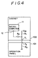
- FIG. 4 shows the internal circuit related to the burglarproof function of the cabinet 100 and the operation panel 101 of the first embodiment.
- the cabinet 100 is provided with a microcomputer 11 as a controller, resistors R1 and R2, a voltage source V DD , and a detachment sense pin T1.
- the operation panel 101 is provided with a register R3 and a detachment sense pin T2.
- the cabinet 100 and the operation panel 101 are detachably connected to each other via the terminals 104 and 105 shown in FIG.3, including the detachment sense pins T1 and T2, respectively.
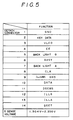
- each of the cabinet 100 and the operation panel 101 includes a connector having 14 pin terminals.
- the pin #11 labeled DENSE is used for determining whether or not the operation panel 101 has been mounted. This determination process is referred to as a detachment sense process.
- a detachment sense voltage is a voltage between, for example, 1.304V and 2.350V. When it is detected that a voltage within the above voltage range is applied to the pin #11, it is determined by the microcomputer 11 that the operation panel 101 has been mounted. It is preferable that the detachment sense voltage be set to a voltage not equal to 0V. Hence, even if the pin #11 is short-circuited, it is not determined that the operation panel 101 has been mounted.
- the detachment sense pin T1 shown in FIG. 4 is fastened to the cabinet 100 and corresponds to the above pin #11, is connected to an A/D (Analog-to- Digital) port 12 of the microcomputer 11.
- a detachment sense circuit which detects whether or not the operation panel 101 has been mounted, is connected to the A/D port 12.
- the A/D port 12 is a circuit that generates digital data indicating a voltage range in which an analog input signal applied to the A/D port 12 is present.
- the A/D port 12 in a case where the A/D port 12 is designed to have an analog input voltage range of 0V to 10V, the A/D port 12 generates digital data "00" when the analog input voltage is between 0V and 2.5V, and data "01” when the analog input voltage is between 2.5V and 5.0V. Further, in the above vase, the A/D port 12 generates digital data "10” when the analog input voltage is between 5.0V and 7.5V, and generates digital data "11” when the analog input voltage is between 7.5V and 10V.
- the detachment sense circuit provided in the cabinet 100 includes the resistors R1 and R2.
- the resistor R1 is connected between a reference power source V DD and the detachment sense pin T1.
- the resistor R2 is connected between the A/D port 12 and the detachment sense pin T1.
- the operation panel 101 includes the detachment sense circuit, which consists of the resistor R3 connected to the detachment sense pin T2 attached to the operation panel 101 and the ground.
- a reference voltage of the reference power source V DD is applied to the A/D port 12 of the microcomputer 11, via the resistors R1 and R2.
- a threshold voltage is 1.7V
- the resistance values of the resistors R1 and R2 are selected so that a voltage applied to the A/D port 12 is between 1.7V and 2.350V (that voltage corresponding to a "H" level).
- the resistance values of the resistors R1 and R2 be selected so that a voltage higher than the threshold voltage is applied to the A/D port 12 in order to make sure the detecting operation.
- the microcomputer 11 detects the "H" voltage between 1.7V and 2.350V applied to the A/D port 12, the microcomputer 11 understands that the operation panel 101 has not been mounted.
- a current from the reference power source V DD flows to the ground via the resistor R1, the detachment sense pin T1 attached to the cabinet 100, the detachment sense pin T2 attached to the operation panel 101, and the resistor R3.
- the resistance value of the resistor R3 is adjusted so that a voltage applied to the A/D port 12 falls into a voltage range between 1.304V and 1.7V (that voltage corresponding to a "L" level).
- the microcomputer 11 detects a voltage within the above voltage range, it understands that the operation panel 101 has duly been mounted. Then, the microcomputer 11 starts to execute a control operation so that electricity is supplied to the operation panel 101, so that the operation panel 101 is activated. In this state, the user can operate the operation panel 101.
- the operation panel 101 it is possible to easily detect whether or not the operation panel 101 has been correctly mounted in the cabinet 100. It is easily possible for different electronic devices to have different detachment sense voltages by adjusting the resistor R3 in the operation panel 101. In this manner, it becomes possible to prevent the electronic device 10 from operating in a state where an operation panel which does not match the operation panel has been mounted, without changing the structure of the contact terminals.
- FIGS. 6 and 7 A description will now be given, with reference to FIGS. 6 and 7, of an on-vehicle electronic device according to a second embodiment of the present invention.
- the cabinet of the second embodiment is the same as that of the first embodiment.
- the second embodiment has an operation panel different from the operation panel 101 of the first embodiment.
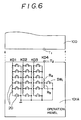
- FIG. 6 shows an operation panel 101A of the second embodiment of the present invention.
- a key switch circuit 20 of the operation panel 101A includes 19 key switches, and 17 resistors. Key data output from the key switch circuit 20 is transferred to the cabinet 100 via four key sense lines KD1 - KD4.
- the key sense line KD4 is also used as a detachment sense circuit.
- a detachment sense voltage is set to be between, for example, 3.1519V and 4.3578V. It is preferable that the detachment sense voltage be set to a voltage other than 0V in order to prevent erroneous understanding such that the operation panel 101A were mounted if the connector is short-circuited by a metal or the like.
- the key sense line KD4 is connected to the A/D port 12 of the micorcomputer 11 via the detachment sense pin T2 attached to the operation panel 101A and the detachment sense pin T1 attached to the cabinet 100.
- a detachment sense circuit which is provided in the cabinet 100 and detects whether or not the operation panel 101A has been mounted, is connected to the A/D port 12.
- the detachment sense circuit provided in the cabinet 100 includes the aforementioned resistor R1 connected to the reference power source V DD and the detachment sense pin T1, and the resistor R2 connected to the A/D port 12 of the microcomputer 11 and the detachment sense pin T1.
- a detachment sense circuit provided in the operation panel 101A includes resistors R4 and R5 connected in series.
- the resistor R4 is connected to the detachment sense pin T2, and the resistor R5 is grounded.
- a switch SW1 is connected between a node at which the resistors R4 and R5 are connected in series to each other and the ground.
- the operation panel 101A includes a connector having 14 terminal pins. As shown in FIG. 6, the operation panel 101A has 19 keys.
- the key sense lines KD1 - KD4 are connected to pins #8 - #11 as shown in FIG. 7, respectively, and are used for determining which one of the 19 keys is pressed.
- the pin #11 is used as the detachment sense pin T2.
- the voltage of the reference power source V DD is applied to the A/D port 12 via the resistors R1 and R2.
- the threshold voltage is 3.75V
- the resistance values of the resistors R1 and R2 are adjusted so that a voltage applied to the A/D port 12 is between 3.75V and 4.3578V (that voltage corresponding to a "H" level ).
- the microcomputer 11 detects the "H" level at the A/D port 12, it understands that the operation panel 101 has not been mounted.
- a current from the reference power source V DD flows to the ground via one of the following two routes.
- One of the routes includes the reference power source V DD , the resistor R1, the detachment sense pin T1 of the cabinet 100, the detachment sense pin T2 of the operation panel 101A, and the resistors R4 and R5.
- the other route includes the reference power source V DD , the resistor R1, the detachment sense pin T1 of the cabinet 100, the detachment sense pin T2 of the operation panel 101A, the resistor R4 and the switch SW1.
- the resistance values of the resistors R4 and R5 are adjusted so that a voltage applied to the A/D port 12 is between 3.1519V and 3.75V (that voltage corresponding to a "L" level).
- the microcomputer 11 detects the "L" level at the A/D port 12, it understands that the operation panel 101A has been mounted. Then, the microcomputer 101A starts to execute a control operation so that electricity is supplied to the operation panel 101A.
- the second embodiment of the present invention it is possible to easily detect whether or not the operation panel 101 has been correctly mounted in the cabinet 100. It is further possible to use a part of the circuit for determining which key is operated in order to form the detachment sense circuit. Hence, it is not necessary to provide an exclusive circuit for forming the detachment sense circuit. Moreover, it is easily possible for different electronic devices to have different detachment sense voltages by adjusting the resistance values of the resistors R4 and R5 in the operation panel 101A. In this manner, it becomes possible to prevent the electronic device from operating in a state where an operation panel which does not match the operation panel has been mounted.
- the third embodiment uses a cabinet identical to the cabinet 100 used in the first and second embodiments.
- the third embodiment is different from the first embodiment in that the detachment sense line is formed by means of a part of the key sense lines, as in the case of the second embodiment. Further, the third embodiment is different from the second embodiment in that a plurality of keys are provided for the detachment sense line.
- FIG. 8A shows an operation panel 101B of the third embodiment of the present invention.
- the input voltage range of the A/D port 12 is divided into six voltage ranges. If it is not necessary to take into account a possibility that an operation panel of another electronic device is mistakenly mounted, in a key switch circuit 30 shown in FIG. 8B, it is possible to commonly use a maximum of four key switches and one data sense line. More particularly, two terminals f are short-circuited, and key switches SWb, SWc, SWd and SWe are provided between terminals b, c, d and e, respectively. When a voltage between 1.3V and 4.79V is detected at the A/D port 12 in the cabinet 100, it is possible to detect that the operation panel 101B has been correctly mounted. It is possible to take into account, in the following manner, the fact an operation panel of another electronic device is mistakenly mounted.
- a key switch is connected between terminals b, and the terminals c are short-circuited.
- key switches are respectively provided between terminals d and terminals e, and the terminals f are short-circuited.
Landscapes
- Engineering & Computer Science (AREA)
- Computer Networks & Wireless Communication (AREA)
- Signal Processing (AREA)
- Fittings On The Vehicle Exterior For Carrying Loads, And Devices For Holding Or Mounting Articles (AREA)
- Burglar Alarm Systems (AREA)
Claims (8)
- Elektronische Fahrzeugeinrichtung mit:
einem an einem Fahrzeug befestigten Gehäuse (100); und
einem Bedienfeld (101), welches abnehmbar im Gehäuse angebracht ist, dadurch gekennzeichnet, daß
das Gehäuse (100) einen ersten Demontage-Abtaststift (T₁) hat und das Bedienfeld einen zweiten Demontage-Abtaststift (T₂) hat, welcher elektrisch an den ersten Demontage-Abtaststift (T₁) angeschlossen ist, wenn das Bedienfeld (101) im Gehäuse (100) eingebaut ist, und
das Gehäuse (100) umfaßt:
eine Bezugs-Stromversorgungsanlage (VDD), welche eine Bezugsspannung an den ersten Demontage-Abtaststift (T₁) anlegt;
eine Spannungs-Erfassungseinrichtung (R₁, R₂) zum Erfassen einer an den ersten Demontage-Abtaststift (T₁) angelegten Spannung; und
eine mit der Spannungs-Erfassungseinrichtung (R₁, R₂) gekoppelte Einbau-Erfassungseinrichtung (11), um auf der Grundlage einer Differenz zwischen einer ersten Erfassungsspannung, welche durch die Spannungs-Erfassungseinrichtung (R₁, R₂) festgestellt wird, wenn das Bedienfeld (101) eingebaut ist, und einer zweiten Erfassungsspannung, welche durch die Spannungs-Erfassungseinrichtung (R₁, R₂) festgestellt wird, wenn das Bedienfeld (101) nicht eingebaut ist, zu bestimmen, ob das Bedienfeld (101) eingebaut und über den ersten und den zweiten Demontage-Abtaststift (T₁, T₂) elektrisch an das Gehäuse (100) angeschlossen ist. - Elektronische Fahrzeugeinrichtung nach Anspruch 1, wobei die Spannungs-Erfassungseinrichtung (R₁, R₂) umfaßt: einen ersten Widerstand (R₁), welcher zwischen der Bezugs-Stromversorgungsanlage (VDD) und dem ersten Demontage-Abtaststift (T₁) angeschlossen ist, und einen zweiten Widerstand (R₂), welcher zwischen der Einbau-Erfassungseinrichtung (11) und dem ersten Demontage-Abtaststift (T₁) angeschlossen ist; und
das Bedienfeld (101) einen dritten Widerstand (R₃) umfaßt, welcher zwischen dem zweiten Demontage-Abtaststiff (T₂) und einem Erdanschluß vorgesehen ist. - Elektronische Fahrzeugeinrichtung nach Anspruch 1 oder 2, wobei das Gehäuse (100) umfaßt: einen ersten Kontaktanschluß (105) mit einer Vielzahl von Anschlußstiften, von denen einer dem ersten Demontage-Abtaststift (T₁) entspricht; und
das Bedienfeld (101) einen zweiten Kontaktanschluß (104) umfaßt, welcher mit dem ersten Kontaktanschluß (105) in Eingriff kommt und eine Vielzahl von Anschlußstiffen aufweist, von denen einer dem zweiten Demontage-Abtaststift (T₂) entspricht. - Elektronische Fahrzeugeinrichtung nach einem der Ansprüche 1 bis 3, wobei das Gehäuse (100) eine Innenklappe (102) umfaßt, die das Bedienfeld (101) abnehmbar lagert.
- Elektronische Fahrzeugeinrichtung nach einem der Ansprüche 1 bis 4, wobei die Einbau-Erfassungseinrichtung (11) einen Mikrocomputer (11) mit einem Analog-Digital-Port (12) umfaßt, an den der erste Demontage-Abtaststift (T₁) elektrisch angeschlossen ist.
- Elektronische Fahrzeugeinrichtung nach Anspruch 1, wobei das Bedienfeld (101) weiterhin eine Vielzahl von Tastschalter-Stromkreisen (20, 30) aufweist;
das Gehäuse (100) außerdem eine Identifizierungseinrichtung (11) für die Tastschalter-Stromkreise umfaßt um zu erkennen, welcher der Tastschalter-Stromkreise (20, 30) betätigt wird, wenn das Bedienfeld (101) in das Gehäuse (100) eingebaut wird; und
die Spannungs-Erfassungseinrichtung (R₁, R₂) die Spannung eines an den ersten Demontage-Abtaststift (T₁) angelegten Signals erfaßt. - Elektronische Fahrzeugeinrichtung nach Anspruch 6, wobei der zweite Demontage-Abtaststift (T₂) über einen Tastschalter (SW₁) geerdet ist, welcher mit einem der Tastschalter-Stromkreise (20, 30) in Verbindung steht.
- Elektronische Fahrzeugeinrichtung nach Anspruch 6, wobei der zweite Demontage-Abtaststift (T₂) über eine Vielzahl von Tastschaltern (SWb, SWc, SWd, SWe) geerdet ist, welche jeweils an die Tastschalter-Stromkreise angeschlossen sind.
Applications Claiming Priority (2)
| Application Number | Priority Date | Filing Date | Title |
|---|---|---|---|
| JP215474/91 | 1991-08-27 | ||
| JP21547491A JP3315131B2 (ja) | 1991-08-27 | 1991-08-27 | 車載用電子機器 |
Publications (2)
| Publication Number | Publication Date |
|---|---|
| EP0529996A1 EP0529996A1 (de) | 1993-03-03 |
| EP0529996B1 true EP0529996B1 (de) | 1995-10-11 |
Family
ID=16672975
Family Applications (1)
| Application Number | Title | Priority Date | Filing Date |
|---|---|---|---|
| EP19920307726 Expired - Lifetime EP0529996B1 (de) | 1991-08-27 | 1992-08-25 | Kraftfahrzeugelektronikeinrichtung |
Country Status (4)
| Country | Link |
|---|---|
| US (1) | US5359230A (de) |
| EP (1) | EP0529996B1 (de) |
| JP (1) | JP3315131B2 (de) |
| DE (1) | DE69205375T2 (de) |
Cited By (1)
| Publication number | Priority date | Publication date | Assignee | Title |
|---|---|---|---|---|
| WO2004042880A1 (en) * | 2002-11-08 | 2004-05-21 | Creative Technology Ltd | Improvements in and relating to audio devices |
Families Citing this family (14)
| Publication number | Priority date | Publication date | Assignee | Title |
|---|---|---|---|---|
| JP2578138Y2 (ja) * | 1992-04-23 | 1998-08-06 | パイオニア株式会社 | カーステレオ |
| EP0960781A3 (de) * | 1993-04-30 | 2000-05-24 | Shintom Co., Ltd | In einem Fahrzeug montiertes Audiogerät |
| JPH08133018A (ja) * | 1994-11-09 | 1996-05-28 | Honda Motor Co Ltd | 車両盗難防止機能無効化防止装置付きエンジン制御手段 |
| US5635769A (en) * | 1996-04-02 | 1997-06-03 | Magnadyne Corporation | Adaptable interface device for control of vehicle accessory systems using a plug-in resistor assembly |
| JPH106884A (ja) * | 1996-06-26 | 1998-01-13 | Alps Electric Co Ltd | 車載機器制御装置 |
| US5831344A (en) * | 1997-01-30 | 1998-11-03 | Rose, Sr.; Robert E. | Vehicle anti-theft system |
| JP3970512B2 (ja) * | 1999-12-14 | 2007-09-05 | アルプス電気株式会社 | 車載機器制御装置 |
| EP1428330B1 (de) * | 2001-09-20 | 2005-05-25 | Honeywell, Inc. | Telefonsteuerung im einem flugdeck |
| JP4513015B2 (ja) * | 2005-06-09 | 2010-07-28 | ソニー株式会社 | 電子機器の筐体ボディ装着用フロントパネルアセンブリおよび車載用電子機器の筐体 |
| DE102005036729A1 (de) * | 2005-08-04 | 2007-02-08 | Robert Bosch Gmbh | Diebstahlsicherungsvorrichtung für Elektrowerkzeugmaschinen sowie Elektrowerkzeugmaschine mit Diebstahlsicherungsvorrichtung |
| US20070079030A1 (en) * | 2005-09-30 | 2007-04-05 | Intel Corporation | Auxiliary display and storage unit |
| TWI271684B (en) * | 2005-10-11 | 2007-01-21 | Delta Electronics Inc | Display device, keypad thereof and method for activating display device |
| JP4654422B2 (ja) * | 2008-02-15 | 2011-03-23 | Necインフロンティア株式会社 | 携帯端末装置 |
| US7976346B2 (en) * | 2009-03-06 | 2011-07-12 | Cisco Technology, Inc. | Interface connection management using a removable adapter for communications equipment |
Family Cites Families (6)
| Publication number | Priority date | Publication date | Assignee | Title |
|---|---|---|---|---|
| JPS6034094Y2 (ja) * | 1979-03-26 | 1985-10-11 | オリンパス光学工業株式会社 | ミユ−テイング回路 |
| JPS6258482A (ja) * | 1985-09-06 | 1987-03-14 | Alpine Electron Inc | 記録媒体演奏装置 |
| JPH02100416A (ja) * | 1988-10-06 | 1990-04-12 | Pioneer Electron Corp | 電子装置 |
| US5107244A (en) * | 1989-07-12 | 1992-04-21 | Pioneer Electronic Corporation | Burglarproof device for electronic equipment adapted to be mounted in vehicles |
| JP2824112B2 (ja) * | 1990-03-09 | 1998-11-11 | パイオニア株式会社 | 電子機器 |
| JPH087990B2 (ja) * | 1990-03-30 | 1996-01-29 | パイオニア株式会社 | 脱着式操作部の保護回路 |
-
1991
- 1991-08-27 JP JP21547491A patent/JP3315131B2/ja not_active Expired - Fee Related
-
1992
- 1992-08-17 US US07/930,999 patent/US5359230A/en not_active Expired - Lifetime
- 1992-08-25 EP EP19920307726 patent/EP0529996B1/de not_active Expired - Lifetime
- 1992-08-25 DE DE69205375T patent/DE69205375T2/de not_active Expired - Fee Related
Cited By (1)
| Publication number | Priority date | Publication date | Assignee | Title |
|---|---|---|---|---|
| WO2004042880A1 (en) * | 2002-11-08 | 2004-05-21 | Creative Technology Ltd | Improvements in and relating to audio devices |
Also Published As
| Publication number | Publication date |
|---|---|
| DE69205375T2 (de) | 1996-05-09 |
| EP0529996A1 (de) | 1993-03-03 |
| US5359230A (en) | 1994-10-25 |
| JP3315131B2 (ja) | 2002-08-19 |
| JPH0558225A (ja) | 1993-03-09 |
| DE69205375D1 (de) | 1995-11-16 |
Similar Documents
| Publication | Publication Date | Title |
|---|---|---|
| EP0529996B1 (de) | Kraftfahrzeugelektronikeinrichtung | |
| US5428752A (en) | Processor system option module identification system | |
| US5363122A (en) | System for controlling a display provided on a car stereo | |
| US5554966A (en) | Car-stereo with removable control panel, alarm, and power conservation | |
| EP0889415A2 (de) | Doppelspannungskartenverbinder | |
| US6191503B1 (en) | Computer with a chassis intrusion detector | |
| JPH04358940A (ja) | グリル電源制御システム | |
| US6260942B1 (en) | Sensor and method for detecting protective tape on a printer cartridge | |
| US6504263B2 (en) | In-car-device controller | |
| JP2550660Y2 (ja) | カーステレオ | |
| KR950004442B1 (ko) | 용지크기 자동감지 방법 및 장치 | |
| JPH0640436B2 (ja) | メモリパツクを備えた電子機器 | |
| KR0162836B1 (ko) | 핸즈프리 키트의 키입력회로 | |
| EP0492311B1 (de) | Gerät zum Nachweis und zur Unterscheidung von Fehlern in einer elektrischen Versorgungsschaltung | |
| JPH07244784A (ja) | パネル装着検出装置 | |
| JP2550661Y2 (ja) | カーステレオ | |
| JPH0446457Y2 (de) | ||
| JP2002196847A (ja) | マイコンの仕向設定方法およびマイコンの仕向設定システム | |
| JPH01169501A (ja) | スイッチ信号読取装置 | |
| JP2684489B2 (ja) | スイッチ装置 | |
| JPH08202474A (ja) | コネクタ接続検出回路 | |
| JP2007114922A (ja) | 拡張ボード | |
| JP2000121690A (ja) | 電子機器の自己診断装置 | |
| JP2570994B2 (ja) | アラーム信号通信装置 | |
| JPH0779239A (ja) | フェイルセーフ機能付通信バス |
Legal Events
| Date | Code | Title | Description |
|---|---|---|---|
| PUAI | Public reference made under article 153(3) epc to a published international application that has entered the european phase |
Free format text: ORIGINAL CODE: 0009012 |
|
| AK | Designated contracting states |
Kind code of ref document: A1 Designated state(s): DE FR GB |
|
| 17P | Request for examination filed |
Effective date: 19930813 |
|
| 17Q | First examination report despatched |
Effective date: 19940526 |
|
| GRAA | (expected) grant |
Free format text: ORIGINAL CODE: 0009210 |
|
| AK | Designated contracting states |
Kind code of ref document: B1 Designated state(s): DE FR GB |
|
| REF | Corresponds to: |
Ref document number: 69205375 Country of ref document: DE Date of ref document: 19951116 |
|
| ET | Fr: translation filed | ||
| PLBE | No opposition filed within time limit |
Free format text: ORIGINAL CODE: 0009261 |
|
| STAA | Information on the status of an ep patent application or granted ep patent |
Free format text: STATUS: NO OPPOSITION FILED WITHIN TIME LIMIT |
|
| 26N | No opposition filed | ||
| REG | Reference to a national code |
Ref country code: GB Ref legal event code: 746 Effective date: 19970901 |
|
| REG | Reference to a national code |
Ref country code: FR Ref legal event code: D6 |
|
| REG | Reference to a national code |
Ref country code: GB Ref legal event code: IF02 |
|
| PGFP | Annual fee paid to national office [announced via postgrant information from national office to epo] |
Ref country code: FR Payment date: 20060808 Year of fee payment: 15 |
|
| PGFP | Annual fee paid to national office [announced via postgrant information from national office to epo] |
Ref country code: DE Payment date: 20060817 Year of fee payment: 15 |
|
| PGFP | Annual fee paid to national office [announced via postgrant information from national office to epo] |
Ref country code: GB Payment date: 20060823 Year of fee payment: 15 |
|
| GBPC | Gb: european patent ceased through non-payment of renewal fee |
Effective date: 20070825 |
|
| REG | Reference to a national code |
Ref country code: FR Ref legal event code: ST Effective date: 20080430 |
|
| PG25 | Lapsed in a contracting state [announced via postgrant information from national office to epo] |
Ref country code: DE Free format text: LAPSE BECAUSE OF NON-PAYMENT OF DUE FEES Effective date: 20080301 |
|
| PG25 | Lapsed in a contracting state [announced via postgrant information from national office to epo] |
Ref country code: FR Free format text: LAPSE BECAUSE OF NON-PAYMENT OF DUE FEES Effective date: 20070831 |
|
| PG25 | Lapsed in a contracting state [announced via postgrant information from national office to epo] |
Ref country code: GB Free format text: LAPSE BECAUSE OF NON-PAYMENT OF DUE FEES Effective date: 20070825 |