EP0530002A1 - IC-Träger oder IC-Fassung - Google Patents
IC-Träger oder IC-Fassung Download PDFInfo
- Publication number
- EP0530002A1 EP0530002A1 EP92307751A EP92307751A EP0530002A1 EP 0530002 A1 EP0530002 A1 EP 0530002A1 EP 92307751 A EP92307751 A EP 92307751A EP 92307751 A EP92307751 A EP 92307751A EP 0530002 A1 EP0530002 A1 EP 0530002A1
- Authority
- EP
- European Patent Office
- Prior art keywords
- engagement
- latch arms
- latch
- base member
- carrier
- Prior art date
- Legal status (The legal status is an assumption and is not a legal conclusion. Google has not performed a legal analysis and makes no representation as to the accuracy of the status listed.)
- Granted
Links
Images


Classifications
-
- H—ELECTRICITY
- H01—ELECTRIC ELEMENTS
- H01R—ELECTRICALLY-CONDUCTIVE CONNECTIONS; STRUCTURAL ASSOCIATIONS OF A PLURALITY OF MUTUALLY-INSULATED ELECTRICAL CONNECTING ELEMENTS; COUPLING DEVICES; CURRENT COLLECTORS
- H01R13/00—Details of coupling devices of the kinds covered by groups H01R12/70 or H01R24/00 - H01R33/00
- H01R13/02—Contact members
- H01R13/10—Sockets for co-operation with pins or blades
- H01R13/14—Resiliently-mounted rigid sockets
-
- H—ELECTRICITY
- H05—ELECTRIC TECHNIQUES NOT OTHERWISE PROVIDED FOR
- H05K—PRINTED CIRCUITS; CASINGS OR CONSTRUCTIONAL DETAILS OF ELECTRIC APPARATUS; MANUFACTURE OF ASSEMBLAGES OF ELECTRICAL COMPONENTS
- H05K7/00—Constructional details common to different types of electric apparatus
- H05K7/02—Arrangements of circuit components or wiring on supporting structure
- H05K7/10—Plug-in assemblages of components, e.g. IC sockets
- H05K7/1015—Plug-in assemblages of components, e.g. IC sockets having exterior leads
- H05K7/103—Plug-in assemblages of components, e.g. IC sockets having exterior leads co-operating by sliding, e.g. DIP carriers
- H05K7/1038—Plug-in assemblages of components, e.g. IC sockets having exterior leads co-operating by sliding, e.g. DIP carriers with spring contact pieces
Definitions
- This invention relates to an IC carrier for carrying thereon an IC for transportation or to be received in an IC socket. From another aspect, the present invention relates to an IC socket to be used for connection to an IC, and particularly to an IC holding construction which is common both to the IC carrier and the IC socket.
- USP4,881,639 owned by the present applicant discloses a one-piece type IC carrier comprising a base member and torsion bars each integrally formed on each corner of the base member, and latch arms integral with the torsion bars, respectively and adapted to engage with an edge portion of an IC placed on the base member.
- each latch arm is pivoted upwardly about its corresponding torsion bar to remove its engagement with the IC.
- a twisting energy is accumulated in the torsion bar, and the latch arm is pivoted downwardly by this twisting energy so as to be brought into engagement its corresponding corner portion of the IC.
- the above carrier is operated to open and close the latch arms while exerting the twisting force to the torsion bars, so that the latch arms are engaged with and disengaged from the IC. Since the twisting force is repeatedly exerted to the torsion bars every time the IC is inserted and removed, the twisting stress is concentrated on connecting portions at both ends of the torsion bars which are integrally connected to the base member. As a result, the connecting portions gradually become fragile and unable to fully exhibit their function. Moreover, since the torsion bars are required to be extended across the corner portions of the base member which has only a limited space, it is difficult to obtain a sufficient length for each of the torsion bars.
- the connecting portions of the torsion bars tend to be more fragile and are subjected to a danger of breakage.
- the torsion bars and the latch arms are integrally formed in the base member, complicated narrow spaces or gaps for defining both of them must be formed therearound, and therefore, molding is not easy.
- the latch arms are integrally formed on the base member such that the latch arms themselves are elastically shifted at the connecting portions, for example, at the above torsion bars, with respect to the base member.
- the latch arms are formed as separate parts from the base member to form a two-piece construction
- the latch arms are pivotably supported relative to the base member through shafts or pins respectively, and the latch arms, when pivoted to positions for engagement with the IC, are brought into engagement with the base member through male and female engagement means in order to hold the IC.
- Such an IC engagement means as just mentioned can obviate such problems as deterioration in elasticity and breakage of the latch arms, the problems being inherent in the one-piece construction.
- the engagement between the male portion and the female portion is not reliable, and they are easily disengaged due to wear of the male and female portions.
- a specific object of the present invention is to provide an IC carrier or IC socket, in which latch arms can exhibit their wholesome function even after they are used repeatedly.
- an IC carrier comprising a base member for carrying thereon an IC, latch arms each pivotably supported on said base member for pivoting between a first position for engaging with an edge portion of said IC and a second position for removing the engagement, and lock tabs each formed on an upper end of each of said latch arms and adapted to engage with and disengage from the edge portion of said IC, said IC carrier further comprising spring elements each projecting from a pivotal portion of each of said latch arms, said spring elements accumulating resilient force while said latch arms being pivoted in a direction for removing the engagement so as to urge said latch arms in a direction for realizing the engagement.
- an IC socket comprising a base member for carrying thereon an IC, latch arms each pivotably supported on said base member for pivoting between a first position for engaging with an edge portion of said IC and a second position for removing the engagement, and lock tabs each formed on an upper end of each of said latch arms and adapted to engage with and disengage from the edge portion of said IC, said IC carrier further comprising spring elements each projecting from a pivotal portion of each of said latch arms, said spring elements accumulating resilient force while said latch arms being pivoted in a direction for removing the engagement so as to urge said latch arms in a direction for realizing the engagement.
- each latch arm when each latch arm is pivoted upwardly while bending the spring element, the arm is disengaged from the IC in order to allow the IC to be removed.
- resilient force is accumulated in each spring element when the latch arm is pivoted in the direction for removing the engagement, and this resilient force causes each latch arm to be pivoted in the direction for realizing its engagement with the IC.
- the latch arms are subjected to resilient deterioration, breakage, etc. due to repeated use thereof as often experienced in the conventional one-piece type IC carrier or IC socket which is integral with the base member.
- the latch arms are subjected to insufficient engagement, erroneous engagement, etc. due to wear of the engaging portions because of repeated use, as often experienced in the two-piece type IC carrier in which the latch arms are pivotably supported on the base member. Even if the IC is repeatedly inserted into and removed from the base member of the IC carrier or IC socket, the latch arms can still exhibit their wholesome function.
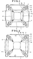
- the numeral 1 denotes a base member which forms a carrier body made of synthetic resin.
- the base member 1 is of a generally square configuration and has an IC accommodation portion 2 formed in and opening at a generally central portion thereof.
- the IC accommodation portion 2 is of a generally square configuration and accommodates therein an IC 3 such that each side of the IC 3 is in parallel relation with each side of the IC accommodation portion 2.
- seat members 4 for supporting each row of a group of leads 7 arranged along and extending sidewards from each side of the IC 3, are formed on opposing two or four sides of the IC accommodation portion 2.
- the IC accommodation portion 2 is defined at an inner area of each seat member 4.
- Each corner portion of the base member 1 is provided with a latch arm 6.
- the latch arm 6 is received in a through-chamber 8 which is opened at both upper and lower surfaces of each corner portion, and pivotably supported on an inner surface of the through-chamber 8 through a shaft portion 5.
- Each latch arm 6 is disposed at angles along a diagonal line of the IC accommodation chamber 2, such that the axis of the shaft portion 5 is perpendicular to the diagonal line. Therefore, each latch arm 6 is pivoted upwardly and downwardly on the diagonal line about the shaft portion 5.
- latch arm 6 is pivoted downwardly, it is engaged with the corresponding corner portion of the IC 3 received in the IC accommodation portion 2, and when the latch arm 6 is pivoted upwardly, it is disengaged from the corresponding corner portion of the IC.
- Each latch arm 6 is provided at an inner end, i.e., upper end, with a lock tab 6a which is removably engaged with the IC 3.
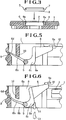
- the shaft portion 5 is pushed into a lower opening portion 8b of the through-chamber 8 so that both ends of the shaft are press-fitted to a bearing portion 8a formed in an inner side wall opposite the lower opening portion.
- the latch arm 6, as shown in Fig. 5, etc. is raised from the shaft portion 5 disposed at a lower surface side of the base member 1 towards an upper opening portion 8a through an elbow portion 6c facing the lower opening portion 8b, and further extended inwardly on the diagonal line along the upper opening portion. A foremost or upper end of the latch arm 6 is provided with the lock tab 6a.
- a spring element 6b extends backwardly from the pivotal support portion of each latch arm 6 pivotably supported by the shaft.
- the latch arm body and the spring element are integrally formed of synthetic resin material.
- the spring element 6b extends on the diagonal line in a direction opposite to the lock tab 6a (i.e., in the extending direction of the latch arm 6).
- a free end 6d of the spring element 6 contacts a spring bearing portion 9 formed of an inclination surface formed on a rear inner wall of the through-chamber 8, or the free end 6d may contact the spring bearing portion 9 when the latch arm 6 is pivoted upwardly.
- the free end portion 6d of the spring element 6b contacts the spring bearing portion 9 thereby preventing a further pivotal movement.
- the spring element 6b is bent to accumulate resilient force.
- a stop 10 for restricting an upward pivotal movement of the spring element 6b is integrally formed on an inner wall of the through-chamber 8.
- the stop 10 is disposed such that when the latch arm 6 is in an engagement position, the stop 10 is in abutment with an upper surface of the spring element 6b and the free end 6d of the spring element 6b is abutted with the spring bearing portion 9.
- each latch arm 6 is connected to a central portion of each shaft portion 5, while a basal portion of each spring element 6b is connected to both end portions of the shaft portion 5.
- the spring element 6b is gradually reduced in width as it goes away from the connecting portion towards the free end portion 6d and also gradually reduced in thickness. The narrowest and thinnest free end portion 6d is operated to contact the spring bearing portion 9.
- each latch arm 6 is provided with an elbow portion 6c facing the lower opening portion 8b of the through-chamber 8.
- a curved outer surface of this elbow portion 6c is formed in an arc form, and this arcuately curved portion is served as a pressure receiving portion 6e for a jig, and the portion 6e is served as shutter means for the latch arm 6.
- the numeral 11 denotes a jig which is operated by a robot.
- the jig 11, as shown in Fig. 6, is vertically movable.
- the latch arm 6 When the jig 11 is moved upwardly, one end of the jig 11 is inserted into the through-chamber 8 through the lower opening portion 8b in order to push up the pressure bearing portion 6e, and as a result, the latch arm 6 is caused to be pivoted upwardly so as to be disengaged from the IC 3. In that state (i.e., the latch arm 6 is in a released state), the IC 3 is inserted into and removed from the IC accommodation portion 2. When the pushing-up force of the jig 11 to the latch arm 6 is removed, the latch arm 6 is automatically pivoted downwardly due to restoring force of the spring element 6b so as to be engaged with an upper surface of the corner portion of the IC 3.
- the upper end face 6f of the latch arm 6 When the lock tab 6a of the latch arm 6 is in engagement with the IC, the upper end face 6f of the latch arm 6 is abutted with a side surface (for example, side surface of the corner portion), and the IC is correctly positioned and held by and between the upper end faces 6f of the opposing latch arms 6. Therefore, the upper end face 6f of each latch arm 6 forms a positioning surface for the IC.
- the lock tab 6a is brought into engagement with the IC which is correctly positioned and held by and between the upper end faces 6f of the opposing latch arms 6.
- the latch arms 6 are in engagement with the opposing corner portions of the IC 3 so that the IC 3 is held on the base member 1.
- the latch members 6 may be engaged with four corners or they may be engaged with two opposing corners of the IC.
- the latch arms 6 may be engaged with those edge portions of the IC 3 which include the corner portions, respectively.
- the latch arms 6, the spring elements 6b, and the shaft portions 6 are integrally formed of synthetic resin.
- the spring elements 6b may be made of metal and integrally formed with the latch portions 6.
- the shaft portions 5 may be metal pins, respectively.
- the present invention is applied to an IC carrier.
- the present invention may be applied to an IC socket.
- an IC socket is formed by implanting a plurality of contacts into the base member 1 such that the contacts can be brought into contact with leads 7 of the IC 3, respectively.
- the contacts are arranged around the IC accommodation portion, for example, the area corresponding to the seat members 4, so that they are readily brought into contact with the IC leads 7, respectively.
- the latch arm 6 is engaged with the edge portion of the IC 3 and served as means for maintaining the foregoing contacting relation.
- the base member is formed in a regular square configuration, and the latch arms are disposed on the diagonal lines.
- the base member takes, for example, a rectangular configuration
- the latch arms are disposed on the diagonal lines, or at angles or parallel with each side of the base member, respectively.
- resilient force is accumulated owing to the spring elements had by the latch arms themselves.
- the latch arms are automatically returned into the engaging direction so as to maintain the engagement with the IC by their own function.
- a similar function as in the one-piece type IC carrier can be realized by a two-piece construction.
- the latch arms are subjected to resilient deterioration due to repeated use thereof and molding is difficult as often experienced in the conventional one-piece type IC carrier or IC socket.
- the latch arms are subjected to insufficient engagement, erroneous engagement, etc. due to wear of the engaging portions because of repeated use, as often experienced in the two-piece type IC carrier or IC socket in which the latch arms are pivotably supported on the base member.
- the latch arms can still exhibit their wholesome function.
Landscapes
- Engineering & Computer Science (AREA)
- Microelectronics & Electronic Packaging (AREA)
- Connecting Device With Holders (AREA)
- Details Of Connecting Devices For Male And Female Coupling (AREA)
- Packaging Of Annular Or Rod-Shaped Articles, Wearing Apparel, Cassettes, Or The Like (AREA)
- Packaging Frangible Articles (AREA)
Applications Claiming Priority (2)
| Application Number | Priority Date | Filing Date | Title |
|---|---|---|---|
| JP245168/91 | 1991-08-30 | ||
| JP3245168A JP2637647B2 (ja) | 1991-08-30 | 1991-08-30 | Icキャリア又はicソケット |
Publications (2)
| Publication Number | Publication Date |
|---|---|
| EP0530002A1 true EP0530002A1 (de) | 1993-03-03 |
| EP0530002B1 EP0530002B1 (de) | 1995-04-26 |
Family
ID=17129624
Family Applications (1)
| Application Number | Title | Priority Date | Filing Date |
|---|---|---|---|
| EP92307751A Expired - Lifetime EP0530002B1 (de) | 1991-08-30 | 1992-08-25 | IC-Träger oder IC-Fassung |
Country Status (7)
| Country | Link |
|---|---|
| US (1) | US5373938A (de) |
| EP (1) | EP0530002B1 (de) |
| JP (1) | JP2637647B2 (de) |
| KR (1) | KR930020779A (de) |
| CA (1) | CA2076265A1 (de) |
| DE (1) | DE69202216D1 (de) |
| MY (1) | MY108291A (de) |
Cited By (2)
| Publication number | Priority date | Publication date | Assignee | Title |
|---|---|---|---|---|
| GB2279824A (en) * | 1993-06-29 | 1995-01-11 | Yamaichi Electronics Co Ltd | IC carrier |
| CN100414784C (zh) * | 2004-04-23 | 2008-08-27 | 广濑电机株式会社 | 电子模块用插座 |
Families Citing this family (11)
| Publication number | Priority date | Publication date | Assignee | Title |
|---|---|---|---|---|
| US5482164A (en) * | 1994-08-03 | 1996-01-09 | Seagate Technology, Inc. | E-block shipping comb |
| KR0122284Y1 (ko) * | 1995-04-13 | 1998-08-17 | 정문술 | 반도체 소자테스트용 금속트레이 유니트 |
| JPH09133121A (ja) * | 1995-11-10 | 1997-05-20 | Matsushita Electric Ind Co Ltd | 部品保持体 |
| DE19745365A1 (de) * | 1997-10-14 | 1999-01-21 | Siemens Ag | Halteeinrichtung für integrierte Schaltungen |
| KR100486412B1 (ko) * | 2000-10-18 | 2005-05-03 | (주)테크윙 | 테스트 핸들러의 테스트 트레이 인서트 |
| JP4231354B2 (ja) * | 2003-07-14 | 2009-02-25 | アルプス電気株式会社 | ソケット装置 |
| KR100950335B1 (ko) * | 2008-01-31 | 2010-03-31 | (주)테크윙 | 테스트핸들러의 캐리어보드용 인서트 |
| TWI411562B (zh) * | 2011-04-22 | 2013-10-11 | Au Optronics Corp | 包裝元件 |
| TWI473202B (zh) * | 2011-12-19 | 2015-02-11 | 財團法人工業技術研究院 | 承載裝置及應用其之基材卸載方法 |
| US20150053586A1 (en) * | 2013-08-22 | 2015-02-26 | Texas Instruments Incorporated | Carrier tape |
| US10101176B2 (en) | 2014-03-13 | 2018-10-16 | Texas Instruments Incorporated | Carrier tape packaging method and apparatus |
Citations (2)
| Publication number | Priority date | Publication date | Assignee | Title |
|---|---|---|---|---|
| CA1261482A (en) * | 1988-06-22 | 1989-09-26 | John J. Kost | Self-contained thermal transfer integrated circuit carrier package |
| US4881639A (en) * | 1988-02-26 | 1989-11-21 | Yamaichi Electric Mfg. Co., Ltd. | IC carrier |
Family Cites Families (13)
| Publication number | Priority date | Publication date | Assignee | Title |
|---|---|---|---|---|
| US3604557A (en) * | 1969-07-24 | 1971-09-14 | Nicholas J Cedrone | Carrier |
| US4379505A (en) * | 1981-10-20 | 1983-04-12 | Gibson-Egan Company | Integrated circuit carrier |
| JPS6081654U (ja) * | 1983-11-10 | 1985-06-06 | 山一電機工業株式会社 | Icパツケ−ジのキヤリア |
| JPH0219421Y2 (de) * | 1984-12-30 | 1990-05-29 | ||
| US4767984A (en) * | 1985-10-04 | 1988-08-30 | Amp Incorporated | Protective fixture for chip carrier |
| US4747483A (en) * | 1986-10-08 | 1988-05-31 | Amp Incorporated | Protective chip carrier handler |
| US4681221A (en) * | 1986-10-30 | 1987-07-21 | International Business Machines Corporation | Holder for plastic leaded chip carrier |
| US4718548A (en) * | 1986-12-19 | 1988-01-12 | Advanced Micro Devices, Inc. | Protective housing for a leadless chip carrier or plastic leaded chip carrier package |
| US4765471A (en) * | 1987-04-10 | 1988-08-23 | Robert Murphy | Electrical component carrier |
| US5026303A (en) * | 1988-03-10 | 1991-06-25 | Yamaichi Electric Manufacturing Co., Ltd. | Slotless type IC carrier |
| US4991714A (en) * | 1989-11-17 | 1991-02-12 | Minnesota Mining And Manufacturing Company | Spring loaded integrated circuit carrier |
| US5203454A (en) * | 1990-10-25 | 1993-04-20 | Strong Leslie G | Method and apparatus for transporting sensitive electronic components |
| JP3035085U (ja) * | 1996-08-26 | 1997-03-11 | 源壹 李 | 合成樹脂糸オーブンクロスの分離装置 |
-
1991
- 1991-08-30 JP JP3245168A patent/JP2637647B2/ja not_active Expired - Fee Related
-
1992
- 1992-08-17 CA CA002076265A patent/CA2076265A1/en not_active Abandoned
- 1992-08-19 MY MYPI92001496A patent/MY108291A/en unknown
- 1992-08-25 EP EP92307751A patent/EP0530002B1/de not_active Expired - Lifetime
- 1992-08-25 DE DE69202216T patent/DE69202216D1/de not_active Expired - Lifetime
- 1992-08-27 KR KR1019920015467A patent/KR930020779A/ko not_active Withdrawn
-
1993
- 1993-12-13 US US08/165,586 patent/US5373938A/en not_active Expired - Lifetime
Patent Citations (2)
| Publication number | Priority date | Publication date | Assignee | Title |
|---|---|---|---|---|
| US4881639A (en) * | 1988-02-26 | 1989-11-21 | Yamaichi Electric Mfg. Co., Ltd. | IC carrier |
| CA1261482A (en) * | 1988-06-22 | 1989-09-26 | John J. Kost | Self-contained thermal transfer integrated circuit carrier package |
Cited By (2)
| Publication number | Priority date | Publication date | Assignee | Title |
|---|---|---|---|---|
| GB2279824A (en) * | 1993-06-29 | 1995-01-11 | Yamaichi Electronics Co Ltd | IC carrier |
| CN100414784C (zh) * | 2004-04-23 | 2008-08-27 | 广濑电机株式会社 | 电子模块用插座 |
Also Published As
| Publication number | Publication date |
|---|---|
| KR930020779A (ko) | 1993-10-20 |
| CA2076265A1 (en) | 1993-03-01 |
| EP0530002B1 (de) | 1995-04-26 |
| DE69202216D1 (de) | 1995-06-01 |
| US5373938A (en) | 1994-12-20 |
| JPH0565186A (ja) | 1993-03-19 |
| MY108291A (en) | 1996-09-30 |
| JP2637647B2 (ja) | 1997-08-06 |
Similar Documents
| Publication | Publication Date | Title |
|---|---|---|
| EP0530002B1 (de) | IC-Träger oder IC-Fassung | |
| US5109980A (en) | Ic carrier with shaft coupling | |
| JPH0729586Y2 (ja) | コネクタ | |
| US5375710A (en) | IC carrier | |
| EP1282925B1 (de) | Rückwandverbinder mit verriegelungsmechanismus | |
| EP0228279B1 (de) | Fassung zum Einstecken eines IC-Bausteines | |
| US6352442B1 (en) | Connector in which a FPC is tightly held between a housing and a movable actuator with being connected to the connector | |
| US4872850A (en) | IC tester socket | |
| US5351836A (en) | Container for plate-like objects | |
| US4188715A (en) | Method of fabricating an insulator for an electrical connector | |
| EP0774802B1 (de) | Elektrischer Verbinder mit internem elastischen Teil | |
| CA1262289A (en) | Ic insertion/extraction tool | |
| EP0241407B1 (de) | Elektrische Buchse | |
| EP0481727A1 (de) | Sockel für ein elektrisches Teil | |
| EP1696514B1 (de) | Verbindungsmittel für ein flexibles Substrat | |
| EP0657965A2 (de) | Elektrischer Verbinder mit verbesserten Kontaktrückhaltemitteln | |
| US6276731B1 (en) | Wafer carrying fork | |
| KR102208275B1 (ko) | 기판 용기용 쿠션 리테이너 | |
| EP0828317B1 (de) | Verbinder für ein Substrat | |
| US6168025B1 (en) | Wafer holding structure for semiconductor wafer containers | |
| US6066009A (en) | Female terminal having preventive structure for permanent strain thereof | |
| US5700155A (en) | Socket for IC package | |
| US3364535A (en) | Clamp-type fastener | |
| GB2047422A (en) | Device for connecting lugs on metal rim of spectacle frame | |
| EP0395325A1 (de) | IC-Träger |
Legal Events
| Date | Code | Title | Description |
|---|---|---|---|
| PUAI | Public reference made under article 153(3) epc to a published international application that has entered the european phase |
Free format text: ORIGINAL CODE: 0009012 |
|
| AK | Designated contracting states |
Kind code of ref document: A1 Designated state(s): DE FR GB IT |
|
| 17P | Request for examination filed |
Effective date: 19930401 |
|
| 17Q | First examination report despatched |
Effective date: 19940705 |
|
| RAP1 | Party data changed (applicant data changed or rights of an application transferred) |
Owner name: YAMAICHI ELECTRONICS CO., LTD. |
|
| GRAA | (expected) grant |
Free format text: ORIGINAL CODE: 0009210 |
|
| AK | Designated contracting states |
Kind code of ref document: B1 Designated state(s): DE FR GB IT |
|
| PG25 | Lapsed in a contracting state [announced via postgrant information from national office to epo] |
Ref country code: IT Free format text: LAPSE BECAUSE OF FAILURE TO SUBMIT A TRANSLATION OF THE DESCRIPTION OR TO PAY THE FEE WITHIN THE PRE;WARNING: LAPSES OF ITALIAN PATENTS WITH EFFECTIVE DATE BEFORE 2007 MAY HAVE OCCURRED AT ANY TIME BEFORE 2007. THE CORRECT EFFECTIVE DATE MAY BE DIFFERENT FROM THE ONE RECORDED.SCRIBED TIME-LIMIT Effective date: 19950426 Ref country code: FR Effective date: 19950426 |
|
| REF | Corresponds to: |
Ref document number: 69202216 Country of ref document: DE Date of ref document: 19950601 |
|
| PG25 | Lapsed in a contracting state [announced via postgrant information from national office to epo] |
Ref country code: DE Effective date: 19950727 |
|
| EN | Fr: translation not filed | ||
| PLBE | No opposition filed within time limit |
Free format text: ORIGINAL CODE: 0009261 |
|
| STAA | Information on the status of an ep patent application or granted ep patent |
Free format text: STATUS: NO OPPOSITION FILED WITHIN TIME LIMIT |
|
| 26N | No opposition filed | ||
| PGFP | Annual fee paid to national office [announced via postgrant information from national office to epo] |
Ref country code: GB Payment date: 19960731 Year of fee payment: 5 |
|
| PG25 | Lapsed in a contracting state [announced via postgrant information from national office to epo] |
Ref country code: GB Free format text: LAPSE BECAUSE OF NON-PAYMENT OF DUE FEES Effective date: 19970825 |
|
| GBPC | Gb: european patent ceased through non-payment of renewal fee |
Effective date: 19970825 |