EP0530384B1 - Commande de machine-outils pour l'usinage simulatané de pièces planes avec plusieurs outils - Google Patents
Commande de machine-outils pour l'usinage simulatané de pièces planes avec plusieurs outils Download PDFInfo
- Publication number
- EP0530384B1 EP0530384B1 EP19910113358 EP91113358A EP0530384B1 EP 0530384 B1 EP0530384 B1 EP 0530384B1 EP 19910113358 EP19910113358 EP 19910113358 EP 91113358 A EP91113358 A EP 91113358A EP 0530384 B1 EP0530384 B1 EP 0530384B1
- Authority
- EP
- European Patent Office
- Prior art keywords
- tool
- carrier
- point
- spindle
- control
- Prior art date
- Legal status (The legal status is an assumption and is not a legal conclusion. Google has not performed a legal analysis and makes no representation as to the accuracy of the status listed.)
- Expired - Lifetime
Links
Images

Classifications
-
- G—PHYSICS
- G05—CONTROLLING; REGULATING
- G05B—CONTROL OR REGULATING SYSTEMS IN GENERAL; FUNCTIONAL ELEMENTS OF SUCH SYSTEMS; MONITORING OR TESTING ARRANGEMENTS FOR SUCH SYSTEMS OR ELEMENTS
- G05B19/00—Program-control systems
- G05B19/02—Program-control systems electric
- G05B19/18—Numerical control [NC], i.e. automatically operating machines, in particular machine tools, e.g. in a manufacturing environment, so as to execute positioning, movement or co-ordinated operations by means of program data in numerical form
- G05B19/408—Numerical control [NC], i.e. automatically operating machines, in particular machine tools, e.g. in a manufacturing environment, so as to execute positioning, movement or co-ordinated operations by means of program data in numerical form characterised by data handling or data format, e.g. reading, buffering or conversion of data
- G05B19/4086—Coordinate conversions; Other special calculations
Definitions
- So-called multiple processing machines are used in the production of plate-shaped workpieces.
- machining technologies are integrated in this machine type, e.g. Drilling, milling, grooving, edge banding.
- all the tools available on the multiple processing machines such as drills, milling cutters, grooving saws, are common attached to a mobile tool carrier. To position a tool at a working position, the entire tool carrier is moved in the plane above the plate-shaped workpiece so that the tool with which a machining operation is to be carried out is located above the machining point.
- the machine tool control must know the position of the respective tool or the respective tool spindle with respect to the tool carrier zero point. Each time a tool selected for machining is specified, the machine tool control must then take into account the position of the machining tool with respect to the tool carrier zero point and move the tool carrier accordingly.
- Drills of the numerical control can be specified individually, so that one command is required for each drill used.
- the first-mentioned document refers to a machine tool controller for machining turned parts, in which only one tool is used to machine a workpiece .
- a symmetrical machining of a workpiece is also known from the latter of the two cited documents, each with its own tool successively machining the workpiece at points symmetrically arranged with respect to one another.
- a mirror-image arrangement of several tools which simultaneously use different tools, for example drills, on a common tool module cannot be derived from this.
- the object of the invention is to obtain a machine tool control with which simple tool module machining is possible.
- a machine tool control for processing plate-shaped workpieces, in particular made of wood or plastic, with a numerical and a programmable control part for controlling the position and the functions of a tool holder in a tool holder coordinate system, with at least one processing unit on the tool holder with at least two using a Gear-driven tool spindles are attached, the tool carrier being assigned a tool carrier reference point and each processing unit an aggregate reference point and being stored in the control system, the position of the tool spindles relative to the aggregate reference points and the position of the aggregate reference points relative to the tool carrier reference point being specified and according to specifications a tool spindle and a position for this in the tool carrier coordinate system, the tool carrier is positioned by the position of a The given tool spindle with regard to the tool carrier reference point is taken into account as a position correction, any tool spindle combinations being specified as tool modules and each tool module being assigned a freely selectable leading tool spindle, with respect to which the positioning in the tool carrier coordinate system takes place.
- Any number of tool modules can be stored once in the memory locations provided for this purpose in the machine tool control system, so that they can be called up at any time for a machining operation.
- the position in the machine tool coordinate system need only be specified for this leading drill.
- the positioning of the tool holder is then carried out by the numerical control with respect to the leading tool spindle as with any other tool spindle.
- the drills involved are automatically selected by the programmable logic controller.
- each tool module can be assigned a mirror-image tool module which is activated by a mirror command.
- a mirror-image tool module which is activated by a mirror command.
- Bores for hinges and fittings can be made at the top and bottom of a plate-shaped workpiece.
- a further advantageous embodiment of the invention wherein a first and a second workpiece zero point are specified in the tool carrier coordinate system, the leading tool spindle being moved to a first point with respect to the first workpiece zero point, whereby after triggering the mirror command, the first point is mirrored with respect to the first workpiece zero point and the mirrored leading spindle is moved to a second point which corresponds to the mirrored point with respect to the second workpiece zero point.
- the machine tool control can be programmed and operated particularly easily by the manufacturer and the user using a graphical user interface in a dialog process.
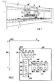
- Fig. 1 shows the schematic representation of a machine tool with a tool holder WT, which is suspended on a machine tool holder 1 movable.
- a tool carrier coordinate system X, Y, Z is assigned to the tool carrier WT, in which it can be positioned using control commands from a machine tool control, not shown.
- Drilling and milling units B are arranged on the tool carrier WT, each of which has at least one, but generally at least two tool spindles, which are generally driven by a gear assigned to each drilling unit.
- the tool spindles hold tools W, for example drills, the tips of which do not necessarily have to be arranged in one plane, as shown in FIG. 1, since tools W of different geometry, for example drills of different diameters and different lengths, can also be used.
- the tool carrier WT can be positioned over a workpiece support 2.
- Plate-shaped workpieces for example chipboard, blockboard, plastic plate, etc.
- the workpieces do not necessarily have to have a flat surface; it only has to be ensured that the tools W are each spaced from the most elevated point of a plate-shaped workpiece.
- a machining operation is to be carried out with a tool W
- this tool must be brought into the working position. For this purpose, it is moved in the axial direction to the workpiece support 2. This shift is effected - usually via the spindle - with an actuator which is controlled by a programmable logic controller. If the selected tool W is in the working position, the machining operation is carried out by an infeed movement of the tool carrier WT in the Z direction.
- the other spindles located in the drilling unit of the selected tool spindle or the selected tool W run idle when they are driven by the same gear.
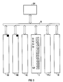
- the position of the tools or the tool spindles W1 ... W21 must be known to the machine tool control so that a corresponding position correction can be carried out within the machine tool coordinate system during the positioning. This is explained below with reference to FIG. 2.
- FIG. 2 shows a tool carrier WT, to which a tool carrier zero point WTO is assigned.
- Three drilling units B1, B2, B3 are attached to the tool carrier WT.
- the drilling unit B1 has the tool spindles W1, W2, W3, the drilling unit W2 the tool spindles W4 ... W7 and the drilling unit B3 the tool spindles W8 ... W15.
- Each drilling unit B1, B2, B3 is one Drilling unit zero assigned to B10, B20, B30.
- the drilling unit zero points B10, B20, B30 are each arranged at a corner of the drilling units B1, B2, B3, since such a corner point is well suited for measuring the tool spindles W1 ... W15.
- the drilling unit zero points could, however, be easily determined at any other point in the coordinate system KW, for example at another exposed point on the tool carrier WT. This position should be selected in such a way that it is as simple as possible to measure the tool spindles W1 ... W15. The same applies to the drilling unit zero points B10, B20, B30 for the tool carrier zero point WTO.
- the position of the drilling unit zero points B10, B20, B30 with respect to the tool carrier zero point WTO is predefined for the machine tool control by vectors V1, V2, V3.
- the position of the tool spindles W1 ... W15 with respect to the drilling unit zero points B10, B20, B30 is also given to the machine tool control system by vectors, of which only the vectors V4, V5, V6 are shown in FIG. 2. Since the machine tool control positions the entire tool holder via the tool holder zero point WT in the machine tool coordinate system KW, the position of this tool spindle must be taken into account as a position correction when positioning a tool spindle W1 ... W15. This position correction can be calculated using vectors V1 ... V6, which can be specified as machine data for the machine tool control.
- This type of specification of the tool spindles W1 ... W15 for the tool carrier zero point allows a simple exchange of drilling units if the same tool carrier WT with a different drilling unit configuration or with drilling units with different spindle equipment is to be used for another type of such machine tool. If the drilling unit zero points B10, B20, B30 are not changed, the machine tool control simply has to be given the new position of tool spindles with respect to these zero points. Secondly, this type of specification of the geometric position of the tool spindles W1 ... W15 permits simple and clear execution or programming of the machine tool control. This is described with reference to FIG. 3.
- Fig. 3 shows the block diagram of a machine tool control with an operating and visualization device BV, which via a bus system B with a memory for setting data SD, a memory for machine data MD, a numerical control part NC, an interface I, a programmable logic controller PLC and an on - Output unit IO is connected.
- the geometrical data of the tools are stored in the memory for the setting data, for example the respective length of the drills fastened in the tool spindles W1 ... W15.
- the geometric position of the tool spindles W1 ... W15, the drilling unit zero points B10, B20, B30 and the tool carrier zero point WT are stored in the memory for the machine data MD.
- the travels for the tool holder are then calculated taking into account the position correction, i.e. the position of a selected tool spindle W1 ... W15 to the tool holder zero point via the respective unit zero point.
- the programmable logic controller PLC then takes over the disengagement of the tool spindles so that the tools are brought into the working position.
- Interface I is provided for the interaction between the numerical control part NC and the programmable control part PLC.
- Interface I has at least memory locations for the "logic zero" and “logic one” states. The number of storage locations corresponds to the number of tool spindles W1 ... W21.
- the user specifies a tool spindle W1 ... W15 and the position in the tool holder coordinate system KW to which this spindle is to be brought via the operating and visualization unit BV.
- the numerical control then calculates the path of the tool holder based on the geometry information stored in the machine data memory.
- the value "logical one" is set in interface I in the memory location assigned to the selected tool spindle.
- the programmable logic controller PLC polls the states of the memory locations S1 ... S21 of the interface I cyclically and issues a control command to the disengaging device of the selected tool spindle via the IO input / output unit, in the example, the tool spindle W4. This process can be carried out by the programmable logic controller PLC at the same time as the numerical control NC is calculating the travel path or the tool carrier is already moving.
- the tool carrier WT is in a Z position relatively close to the workpiece, so that a tool to be brought into the working position would come into contact with the workpiece even before the tool carrier is in the correct position.
- the Z position must be corrected beforehand.
- the length of the tools installed in the spindles W1 ... W15 can be stored in the memory for the setting data SD.
- the numerical control NC will then first check whether the tool carrier is in a Z position, which ensures a safety distance between the tool and the workpiece when the tool spindle is disengaged, and if necessary correct this Z position before positioning in the XY direction and only then in Interface I set the corresponding bit for the tool spindle W1 ... W21.
- Tool module processing makes it possible to select several tools at the same time with just one command and to execute a machining process with them.
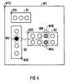
- FIG. 4 again shows the tool carrier WT with the tool carrier zero point WTO and the drilling units B1, B2, B3 and the drilling unit zero points B10, B20, B30.
- the tool spindles W5, W10, W14 are selected as drilling modules or - since they do not necessarily have to be drills - as tool modules.
- the tool spindle W5 is black and the tool spindles W10 to W14 are drawn with dashed lines.
- the tool spindle W5 is stored as a so-called leading drill in the data area SD of the machine tool control.
- the tool spindles W10 and W14 are referred to as involved drills and are also stored in the control. Leading and involved drills or tool spindles of a tool module can be freely configured by the user.
- the execution of a positioning and machining process is just as simple as the positioning of an individual tool already described.
- the user does not just specify a single tool spindle and its position, but rather specifies the corresponding tool module and the position at which the leading drill W5 of the tool module is to be positioned.
- the numerical control NC then calculates the travel path of the tool carrier WT with respect to the leading drill W5 and positions it accordingly.
- Interface I no longer only sets 1 bit for a tool spindle, but instead the associated memory locations S5, S10, S14 with the status "logical one" are set for all tool spindles W5, W10, W14 belonging to the tool module, so that the programmable logic controller PLC all involved and the leading drill of a tool module can be brought into working position.
- mirror-image hole configurations (example: fitting fittings to doors and windows etc.). Such mirror-image hole configurations can be implemented, as will be described below with reference to FIG. 5.
- FIG. 5 shows a tool carrier WT with its associated zero point WTO, which is equipped with an unspecified (rectangle) and a drilling unit B4.
- the drilling unit B4 has 6 tool spindles W16 to W21, which are arranged symmetrically to a line of symmetry SL.
- the tool spindles W16, W17, W18 are each assigned a symmetrical tool spindle W19, W20, W21.
- the tool spindles W16, W18, W19 are selected as the tool module, the tool spindle W16 being the leading tool spindle and the tool spindles W18, W19 being the tool spindles involved.
- the tool module is mirrored by triggering a mirror command by assigning the mirror-image tool spindle to each tool spindle of the tool module.
- the tool spindle W21 becomes the leading and the tool spindles W19, W18 become involved tool spindles of the mirrored tool module.
- a first workpiece zero point KW1 and a second workpiece zero point KW2 are defined in the machine tool coordinate system KW with the coordinates X, Y, Z and the zero point KW0. These workpiece zero points KW1, KW2 are each located in the corner points of a stop device which are attached to the workpiece support 2 known from FIG. 1.
- the workpiece carrier is now positioned via the machine tool control so that the leading tool spindle W16 of the tool module at the position X'1, Y'1 with respect to the Workpiece zero coordinate system X ', Y' is brought.
- the corresponding hole configuration (W19), (W18), (W16) can then be introduced into the workpiece W1 by the infeed movement of the tool carrier in the Z direction.
- the second workpiece W2 can be placed on the second workpiece stop A2.
- the tool module is automatically mirrored and the coordinates X2, Y2 with respect to the coordinate system X "2, Y" 2 are calculated for the mirrored leading tool spindle W21, where X "2 is equal to X'1 and Y''2 is equal to -Y'11.
- the tool carrier WT can then be positioned by the numerical control NC and the mirrored hole configuration (W21), (W19), (W18) corresponding to the tool module. be introduced into the workpiece W2.
Landscapes
- Engineering & Computer Science (AREA)
- Human Computer Interaction (AREA)
- Manufacturing & Machinery (AREA)
- Physics & Mathematics (AREA)
- General Physics & Mathematics (AREA)
- Automation & Control Theory (AREA)
- Numerical Control (AREA)
Claims (5)
- Procédé de commande d'une machine-outil destinée à l'usinage de pièces en forme de plaques, notamment en bois ou en matière plastique, comportant une commande numérique de positionnement (X,Y,Z) et de commande du fonctionnement d'un porte-outils (WT) dans un système (KW) de coordonnées du porte-outils,selon lequel au moins une unité d'usinage (B1 à B3) comportant au moins deux broches d'outils (W1 à W15) entraînées d'une manière synchrone par l'intermédiaire d'une transmission, est disposée sur le porte-outils,selon lequel on associe un point de référence (WTO) du porte-outils au porte-outils (WT) et un point de référence (B10 à B30) d'unité d'usinage (B1 à B3) chaque unité d'usinage et on l'enregistre dans la commande,selon lequel on prescrit la position des broches d'outils (W1 à W21) par rapport aux points de référence (B10 à B30) d'unité, et la position des points de référence (B10...B30) d'unité par rapport au point de référence (WTO) du porte-outils,selon lequel après prescription d'une broche d'outil (W1 à W21) et d'une position pour cette broche dans le système de coordonnées du porte-outils, on effectue un positionnement du porte-outils (WT), en tenant compte, en tant que correction de position, de la position de cette broche d'outil prescrite (W1 à W21) par rapport au point de référence (WTO) du porte-outils,selon lequel on prescrit des combinaisons quelconques de broches d'outils (Wx, Wy, Wz) en tant que modules d'outils et on associe à chaque module d'outil une broche d'outil pilote, qui peut être sélectionnée et par rapport à laquelle le positionnement dans le système (KW) de coordonnée du porte-outils s'effectue.
- Procédé pour la commande d'une machine-outil suivant la revendication 1, selon lequel à un module d'outil est associé un module d'outil symétrique comme dans un miroir, qui, le cas échéant, est activé par une instruction symétrique.
- Procédé de commande d'une machine-outil suivant la revendication 2, selon lequel on prescrit un premier point zéro (KW1) et un second point zéro (KW2) de la pièce à usiner dans le système de coordonnées du porte-outils, selon lequel on déplace la broche d'outil pilote (W1 à W15) jusqu'à un premier point (X1,Y1) par rapport au premier point zéro (KW1) de la pièce à usiner, selon lequel après déclenchement de l'instruction de symétrie, on forme le symétrique du premier point (X1,Y1) par rapport au premier point zéro (KW1) de la pièce à usiner, et selon lequel on déplace la broche pilote rendue symétrique jusqu'à un second point (X"2, Y"2), qui correspond au point (X'1, -Y'1) symétrique du second point zéro (KW2) de la pièce à usiner.
- Procédé de commande d'une machine-outil suivant l'une des revendications précédentes, selon lequel on prescrit toutes les données géométriques, corrections d'outils et les configurations de modules d'outils sont pour la commande, selon une procédure de dialogue, par l'intermédiaire d'un guide graphique de l'utilisateur.
- Procédé de commande d'une machine-outil suivant la revendication 4, selon lequel on visualise la broche d'outil pilote (W1 à W21) d'un module d'outil séparément sur un appareil de visualisation (BV) de l'utilisateur.
Priority Applications (2)
| Application Number | Priority Date | Filing Date | Title |
|---|---|---|---|
| DE59107215T DE59107215D1 (de) | 1991-08-08 | 1991-08-08 | Werkzeugmaschinensteuerung zur gleichzeitigen Bearbeitung von plattenförmigen Werkstücken mit mehreren Werkzeugen |
| EP19910113358 EP0530384B1 (fr) | 1991-08-08 | 1991-08-08 | Commande de machine-outils pour l'usinage simulatané de pièces planes avec plusieurs outils |
Applications Claiming Priority (1)
| Application Number | Priority Date | Filing Date | Title |
|---|---|---|---|
| EP19910113358 EP0530384B1 (fr) | 1991-08-08 | 1991-08-08 | Commande de machine-outils pour l'usinage simulatané de pièces planes avec plusieurs outils |
Publications (2)
| Publication Number | Publication Date |
|---|---|
| EP0530384A1 EP0530384A1 (fr) | 1993-03-10 |
| EP0530384B1 true EP0530384B1 (fr) | 1996-01-03 |
Family
ID=8207027
Family Applications (1)
| Application Number | Title | Priority Date | Filing Date |
|---|---|---|---|
| EP19910113358 Expired - Lifetime EP0530384B1 (fr) | 1991-08-08 | 1991-08-08 | Commande de machine-outils pour l'usinage simulatané de pièces planes avec plusieurs outils |
Country Status (2)
| Country | Link |
|---|---|
| EP (1) | EP0530384B1 (fr) |
| DE (1) | DE59107215D1 (fr) |
Families Citing this family (2)
| Publication number | Priority date | Publication date | Assignee | Title |
|---|---|---|---|---|
| DE19646772C2 (de) * | 1996-11-13 | 2000-08-24 | Heidenhain Gmbh Dr Johannes | Vorrichtung und Verfahren zur Steuerung einer Werkzeugmaschine |
| CN103521808A (zh) * | 2012-10-18 | 2014-01-22 | 芜湖聚达汽车零部件有限公司 | 一种钻床的电路系统 |
Family Cites Families (3)
| Publication number | Priority date | Publication date | Assignee | Title |
|---|---|---|---|---|
| US4422150A (en) * | 1980-05-23 | 1983-12-20 | The Boeing Company | Machine tool controller and part inspection monitor |
| JP2701022B2 (ja) * | 1984-05-22 | 1998-01-21 | ファナック 株式会社 | プログラマブルミラーイメージ機能を有する数値制御装置 |
| JPS61244444A (ja) * | 1985-04-19 | 1986-10-30 | Hitachi Seiki Co Ltd | 工作機械のワ−ク座標系設定装置 |
-
1991
- 1991-08-08 EP EP19910113358 patent/EP0530384B1/fr not_active Expired - Lifetime
- 1991-08-08 DE DE59107215T patent/DE59107215D1/de not_active Expired - Fee Related
Also Published As
| Publication number | Publication date |
|---|---|
| EP0530384A1 (fr) | 1993-03-10 |
| DE59107215D1 (de) | 1996-02-15 |
Similar Documents
| Publication | Publication Date | Title |
|---|---|---|
| DE60116992T2 (de) | Werkzeugmaschine mit mindestens zwei Bearbeitungseinheiten | |
| DE69523906T2 (de) | Maschinensteuerung | |
| EP1762919B1 (fr) | Système de simulation | |
| EP0470350A2 (fr) | Machine multibroche pour percer, fraiser ou travaux similaires | |
| DE3921042A1 (de) | Werkzeugmaschine | |
| DE3308764A1 (de) | Verfahren zum steuern der werkzeugauswahl in einer quadriaxial-numerisch gesteuerten drehbank | |
| DE1627089A1 (de) | Verfahren und Einrichtung zum genauen Einstellen des Abstandes zwischen einem Werkzeug und einem Werkstueck bei einer Werkzeugmaschine | |
| DE10039970B4 (de) | Bearbeitungszentrum und Verfahren zum Bearbeiten von mehreren Werkstücken | |
| DE102015111964A1 (de) | Servomotoren-Steuersystem, das die Bearbeitungspräzision mehrerer Achsen verbessert | |
| DE102014109578B4 (de) | Flügelrad mit einem Blatt, dessen Blattoberfläche aus Linienelementen besteht, und Verfahren zur Bearbeitung des Flügelrads | |
| DE3787250T2 (de) | Numerische regelvorrichtung. | |
| DE60130374T2 (de) | Automatische drehbank, verfahren ihrer steuerung und einrichtung zu ihrer steuerung | |
| DE69205079T2 (de) | Verfahren zum wieder-in-betrieb-setzen einer stanzmaschine und numerisch gesteuertes gerät. | |
| DE3872612T2 (de) | Drehbank, versehen mit steuereinrichtung. | |
| DE1966794B2 (de) | Einrichtung zur numerischen Steuerung von Werkzeugmaschinen mittels einer zentralen Datenverarbeitungsanlage | |
| DE3307615C2 (fr) | ||
| DE102020203770A1 (de) | Steuergerät und Werkzeugmaschine | |
| DE69214757T2 (de) | Numerische Steuerungseinheit mit Positionszählersteuerung und Anzeige | |
| DE10359251A1 (de) | Vorrichtung zur Automatisierung von Werkzeug- oder Produktionsmaschinen | |
| DE69218563T2 (de) | Verfahren zur bewegungssimulationsdarstellung für eine numerische steuerung einer mehrfachdrehbank | |
| DE3530783A1 (de) | Kombinierte anlage fuer die elektroerosion mittels draht und werkzeug | |
| EP0530384B1 (fr) | Commande de machine-outils pour l'usinage simulatané de pièces planes avec plusieurs outils | |
| DE2165723A1 (de) | Bearbeitungs-, insbesondere bohrmaschine mit auswechselbaren werkzeugen und entsprechend waehlbaren geschwindigkeitsstufen | |
| EP0113379B1 (fr) | Coupleur pour processeurs | |
| DE3700887A1 (de) | Numerische steuervorrichtung |
Legal Events
| Date | Code | Title | Description |
|---|---|---|---|
| PUAI | Public reference made under article 153(3) epc to a published international application that has entered the european phase |
Free format text: ORIGINAL CODE: 0009012 |
|
| 17P | Request for examination filed |
Effective date: 19920508 |
|
| AK | Designated contracting states |
Kind code of ref document: A1 Designated state(s): CH DE FR IT LI |
|
| 17Q | First examination report despatched |
Effective date: 19940524 |
|
| GRAA | (expected) grant |
Free format text: ORIGINAL CODE: 0009210 |
|
| AK | Designated contracting states |
Kind code of ref document: B1 Designated state(s): CH DE FR IT LI |
|
| REF | Corresponds to: |
Ref document number: 59107215 Country of ref document: DE Date of ref document: 19960215 |
|
| REG | Reference to a national code |
Ref country code: CH Ref legal event code: NV Representative=s name: SIEMENS-ALBIS AKTIENGESELLSCHAFT |
|
| ITF | It: translation for a ep patent filed | ||
| ET | Fr: translation filed | ||
| PLBE | No opposition filed within time limit |
Free format text: ORIGINAL CODE: 0009261 |
|
| STAA | Information on the status of an ep patent application or granted ep patent |
Free format text: STATUS: NO OPPOSITION FILED WITHIN TIME LIMIT |
|
| 26N | No opposition filed | ||
| PGFP | Annual fee paid to national office [announced via postgrant information from national office to epo] |
Ref country code: CH Payment date: 19971119 Year of fee payment: 7 |
|
| PGFP | Annual fee paid to national office [announced via postgrant information from national office to epo] |
Ref country code: FR Payment date: 19980826 Year of fee payment: 8 |
|
| PG25 | Lapsed in a contracting state [announced via postgrant information from national office to epo] |
Ref country code: LI Free format text: LAPSE BECAUSE OF NON-PAYMENT OF DUE FEES Effective date: 19980831 Ref country code: CH Free format text: LAPSE BECAUSE OF NON-PAYMENT OF DUE FEES Effective date: 19980831 |
|
| REG | Reference to a national code |
Ref country code: CH Ref legal event code: PL |
|
| PGFP | Annual fee paid to national office [announced via postgrant information from national office to epo] |
Ref country code: DE Payment date: 19991019 Year of fee payment: 9 |
|
| PG25 | Lapsed in a contracting state [announced via postgrant information from national office to epo] |
Ref country code: FR Free format text: LAPSE BECAUSE OF NON-PAYMENT OF DUE FEES Effective date: 20000428 |
|
| REG | Reference to a national code |
Ref country code: FR Ref legal event code: ST |
|
| PG25 | Lapsed in a contracting state [announced via postgrant information from national office to epo] |
Ref country code: DE Free format text: LAPSE BECAUSE OF NON-PAYMENT OF DUE FEES Effective date: 20010501 |
|
| PG25 | Lapsed in a contracting state [announced via postgrant information from national office to epo] |
Ref country code: IT Free format text: LAPSE BECAUSE OF NON-PAYMENT OF DUE FEES Effective date: 20050808 |