EP1762919B1 - Système de simulation - Google Patents
Système de simulation Download PDFInfo
- Publication number
- EP1762919B1 EP1762919B1 EP06018827.3A EP06018827A EP1762919B1 EP 1762919 B1 EP1762919 B1 EP 1762919B1 EP 06018827 A EP06018827 A EP 06018827A EP 1762919 B1 EP1762919 B1 EP 1762919B1
- Authority
- EP
- European Patent Office
- Prior art keywords
- program
- control
- production
- production facility
- facility according
- Prior art date
- Legal status (The legal status is an assumption and is not a legal conclusion. Google has not performed a legal analysis and makes no representation as to the accuracy of the status listed.)
- Active
Links
Images




Classifications
-
- G—PHYSICS
- G05—CONTROLLING; REGULATING
- G05B—CONTROL OR REGULATING SYSTEMS IN GENERAL; FUNCTIONAL ELEMENTS OF SUCH SYSTEMS; MONITORING OR TESTING ARRANGEMENTS FOR SUCH SYSTEMS OR ELEMENTS
- G05B19/00—Program-control systems
- G05B19/02—Program-control systems electric
- G05B19/18—Numerical control [NC], i.e. automatically operating machines, in particular machine tools, e.g. in a manufacturing environment, so as to execute positioning, movement or co-ordinated operations by means of program data in numerical form
- G05B19/406—Numerical control [NC], i.e. automatically operating machines, in particular machine tools, e.g. in a manufacturing environment, so as to execute positioning, movement or co-ordinated operations by means of program data in numerical form characterised by monitoring or safety
- G05B19/4069—Simulating machining process on screen
-
- G—PHYSICS
- G05—CONTROLLING; REGULATING
- G05B—CONTROL OR REGULATING SYSTEMS IN GENERAL; FUNCTIONAL ELEMENTS OF SUCH SYSTEMS; MONITORING OR TESTING ARRANGEMENTS FOR SUCH SYSTEMS OR ELEMENTS
- G05B2219/00—Program-control systems
- G05B2219/30—Nc systems
- G05B2219/36—Nc in input of data, input key till input tape
- G05B2219/36252—Generate machining program based on a simulation to optimize a machine parameter
-
- G—PHYSICS
- G05—CONTROLLING; REGULATING
- G05B—CONTROL OR REGULATING SYSTEMS IN GENERAL; FUNCTIONAL ELEMENTS OF SUCH SYSTEMS; MONITORING OR TESTING ARRANGEMENTS FOR SUCH SYSTEMS OR ELEMENTS
- G05B2219/00—Program-control systems
- G05B2219/30—Nc systems
- G05B2219/50—Machine tool, machine tool null till machine tool work handling
- G05B2219/50144—Machine tool, machine tool null till machine tool work handling offline setup by simulation of process, during machining, forming of other piece
Definitions
- the invention relates to a production device for workpieces comprising at least one production area in which a plurality of machine tools provided with a machine control are arranged, a data processing unit which is coupled to the machine controls of the machine tools via a communication path, and with a program which CNC machining program complexes for processing of workpieces makes the machine tools available.
- the US 6,101,425 discloses a manufacturing facility having a manufacturing area in which are arranged a plurality of machine tools provided with a machine control, further comprising data processing units which are coupled to the machine controls of the machine tools via a communication path and provided with a program containing CNC machining program complexes for the Machining of workpieces provides the machine tools.
- a manufacturing device according to the invention has all the features of claim 1.
- the advantage of the solution according to the invention is to be seen in the fact that it allows the machine operator, who supervises the machine tools of a production area, additionally a simulation system to hand in which he can create or test CNC machining program complexes or prepare to retract a CNC machining program complex on a real machine tool to minimize the time required to retract the CNC machining program complex on the real machine tool.
- the production facility has several production areas, which are coupled to the production organization system, so that with the manufacturing organization system, a complex manufacturing network can be organized and then created in this complex composite CNC machining program complexes created by the simulation system, or tested can be used to prepare for the start.
- the production organization system provides the simulation system with CNC machining program complexes for the simulation of actions of virtual machining units on a virtual machine tool.
- the hardware realization of such a production device provides that the production organization system has an organization communication unit with at least one communication interface, and that the machine control is coupled to the at least one communication interface.
- the organization communication unit has a further communication interface with which the at least one simulation system is coupled.
- a particularly favorable solution provides that the communication interface for the at least one simulation system and the at least one communication interface for the at least one machine controller are designed substantially identical.
- This solution has the great advantage that it allows the hardware design of the production unit to be constructed cost-effectively, since the same interfaces can be used both for communication with the at least one machine control and for communication with the at least one simulation system.
- the orgonization communication unit has an organization communication program for communication with the at least one machine control.
- the organization communication unit has an organization communication program for communication with the at least one simulation system.
- the organization communication program for communication with the at least one machine control is substantially identical to the organization communication program for communication with the at least one simulation system.
- the respective machine controller is preferably assigned a communication unit with a communication program for communication with the production organization system.
- the respective simulation system is assigned a communication unit with a communication program for communication with the production organization system.
- the communication program of the respective simulation system operates with identical data formats and data specification, such as the communication program assigned to the respective machine control.
- the solution according to the invention is particularly favorable when it is possible to transfer CNC machining program complexes processed by the machine control to the production organization system, since in this case it is then possible to reuse corrected or corrected CNC machining program complexes on the respective machine control systems. Machining program complexes can then be used without further measures and corrections.
- CNC machining program complexes simulated by the respective simulation system can be transferred to the production organization system, so that the possibility exists of generating or correcting the CNC machining program complexes generated or corrected in the simulation directly for a real machine control of a real machine tool use.
- the production device can be operated in a particularly simple manner if the production organization system manages CNC machining program complexes transmitted by the respective simulation system in the same way as CNC machining program complexes transmitted by the at least one machine control, so that no differentiation with regard to the handling of the CNC at the level of the production organization system Processing program complexes is required, regardless of their origin of machine controls or simulation systems of the manufacturing facility.
- the production organization system receives feedback from the at least one machine controller with regard to the execution of the respective CNC machining program complex therein.
- the manufacturing organization system can optimally organize the further manufacturing.
- the production organization system receives feedback from the respective simulation system with regard to the execution of the respective CNC machining program complex, so that it is also already possible to record how the CNC machining program complex can be processed by the simulation system and whether during this processing For example, malfunctions or delays due to program errors and corrections required in this context occur.
- the feedback from the at least one machine controller and the feedback from the simulation system have a substantially identical structure.
- the production organization system transmits the control instructions to the at least one machine control.
- control instructions for example, at least one CNC machining program complex can be transferred or retransmitted from the manufacturing organization system to the machine control, or a start of the CNC machining program complex can be initiated on the machine control.
- the production organization system transmits control instructions to the respective simulation system, which may also involve the transfer of CNC machining program complexes back and forth, or at least the preparation of the start of simulation processes.
- control instructions for the at least one machine control and the control instructions for the respective simulation system have a substantially identical structure, so that the processing of the control statements in the production organization system can be made uniform, regardless of whether these control instructions to turn on a machine control or to a simulation system.
- the production organization system has a data memory for the CNC machining program complexes, so that the CNC machining program complexes can be temporarily stored in the production organization system and transferred to the individual machine tools or simulation systems depending on production planning.
- CNC machining program complexes for the production organization program are unchecked by a properties field or simulation tested are recognizable, so that the manufacturing facility has the ability to recognize the unchecked CNC machining program complexes and assign them to a simulation system for verification at a given time.
- the production organization program is able to recognize a simulation-tested CNC machining program complex and then allocate it to the real machine control of this machine tool for retraction on a real machine tool.
- CNC machining program complexes for the production organization program can be recognized as being production-tested by the properties field, so that the production organization program is able to assign these programs for the immediate start of processing to a machine control.
- an advantageous embodiment of a production device provides that the production organization system manages the CNC machining program complexes workpiece-related and thus also transfers workpiece-related, whereby the entire handling of the CNC machining program complexes can be simplified.
- the simulation system comprises an operator control with a third data processing unit, which operates the action control with an operating program and the operating program has a program management function, which of the stored in a memory of the third data processing unit CNC machining program complex for Execution of the same the action control at least parts of the same workpiece-related transfers.
- the advantage of the solution according to the invention is thus to be seen in the fact that the operating program is easier to use with the program management function, the program parts required for the execution of individual actions workpiece related or job-related, so that the operator does not call the program parts independently, put together and the action control but that this workpiece-related transfer is carried out independently by the program management function of the operating program.
- Machining units in the sense of this patent application are understood to mean units of a machine tool which are arranged on a machine bed or machine frame and are required for the machining of a workpiece, including the systems assigned to these units for producing a relative movement with respect to the machine bed or machine frame.
- the representation of actions of the processing units in the context of the solution according to the invention is carried out by presenting a predetermined by the machine model outer contour of the processing unit, substantially the entire processing unit in conjunction with a predetermined by the machine frame outer contour thereof, optionally supplemented by the outer contour of other peripheral units, such as Maschinen Industrieszu réelle- and Abbig Roaden or workpiece detection or surveying equipment.
- the representation of the virtual processing units and of the machine frame or machine bed takes place essentially in three dimensions, so that all spatial collision possibilities can be detected and recognized.
- the operating control is associated with a machine control panel.
- Such a machine control panel allows the operator to deal with the CNC machining program complex during the simulation in a manner known to the machine controller.
- the machine control panel has manual input elements, preferably function keys with which the functions can be called up, for activating individual functions of the operating program.
- the work with the operating program can greatly simplify insofar as no program commands must be entered via a keypad, but already sufficient manual operation of the input elements to a single user interface of the operating program, the individual program commands for the individual functions Enter operating program.
- an advantageous embodiment of a solution according to the invention provides that the machine control panel has manual input elements for acting on the CNC machining program complex.
- An example of such an action on the CNC machining program complex would be, for example, triggering a movement of a selected machining unit in accordance with a manual operation of the input elements, so that, for example, the machining unit changes its position.
- Another effect would be a movement of the processing unit according to the manual operation of the input elements, such as the rotation of a turret.
- Another possibility of acting on the CNC machining program complex would be, for example, switching on a drive for a spindle or a drive for a driven tool.
- the operating program must perform complex operations. First, the corresponding parts programs of the action control to pass, then these are to be started and, finally, the actions of the processing units according to the specified manual operation of the input elements to monitor and then stop the corresponding part programs again.
- a further advantageous solution provides that the machine control panel has manual input elements for operating functions of the action control, wherein an actuation of these manual input elements results in directly activating or stopping functions of the action control.
- An example of such functions of the action control would be the immediate intervention in the sequence of one or more part programs by their immediate stop or their immediate activation in the action control, in which case the action on the action control via corresponding functions of the operating program, the at Actuation of the manual input elements can be activated directly.
- a further advantageous embodiment of a simulation system according to the invention provides that the operator control is coupled to a display panel of the machine control panel and that the operator control displays information provided by the operator program for displaying an operator on the display panel.
- the operation of the simulation system is further simplified, as it is possible to display information selected by the operating program in addition to the virtual machine tool with the virtual processing units.
- the machine control panel can be assigned as a hardware component to the visualization system according to the invention.
- the machine control panel is a virtual machine control panel, which is shown on a visualization unit.
- This solution has the great advantage that the appearance and in particular the arrangement of the input elements of the machine control panel can be adapted to the requirements of the CNC machining program complex or, in particular, to the requirements of the operator with regard to ease of use by software changes.
- the simulation system according to the invention can also be adapted to the respective conditions of the machine tool with regard to the operating options of the operating program and the provided functions, in particular the intended input elements, so that the operator has access to the Simulation system always to provide the machine control panel, which the operator also finds on the machine tool for which the CNC machining program complex is designed or needs to be designed.
- an advantageous embodiment provides that the program management function of the operating program manages part programs of the CNC machining program complex workpiece-related.
- This solution has the advantage that the program management function always manages the part programs relating to a workpiece or a job together, so that the operator no longer has the need to locate the individual part programs belonging to a workpiece and to manage each accordingly.
- the backup of the part programs is simplified when the program management function of the operating program secures part programs of the CNC machining program complex workpiece-related, that is, in particular on an external data storage, ensures.
- an advantageous solution provides that the program management function of the operating program transmits part programs of the CNC machining program complex to the workpiece-related action control.
- the program management function of the operating program distributes and activates part programs of the CNC machining program complex workpiece-related to individual channels of the action control.
- the program management function automatically recognizes the individual channels of the control program of the action control and then assigns these individual channels to the corresponding part programs.
- an advantageous simulation system provides that the operating program comprises a program processing function with which the CNC machining program complex can be changed by accessing at least program parts of the CNC machining program complex.
- the program processing function comprises a program creation mode.
- Such a program creation mode offers the advantage of creating or correcting directly on the parts of the CNC machining program complex in the programming system according to the invention, so that when detecting unwanted actions in the simulation in a simple way, the possibility to change the actions or other alternative To test actions.
- the program processing function comprises an input mode for correction values.
- Correction values of this kind can be, for example, corrections for positions of machining units or also for individual modes of operation of the machining units, such as rotational speeds.
- the processing of the CNC machining program complex is further facilitated by the program editing function independently adopting a program change into the CNC machining program complex, so that the operator need not expressly take care of this.
- the program processing function independently reloads the part programs present in the action control into the operating control for modification.
- This feature has the great advantage that the operator does not have to call up the individual program units and transfer them back to the programming station, as in the case of known simulation systems. Rather, when the program processing function is called, then immediately when the respective part program is loaded in the action control, reloaded the part program from the action control in the control panel for change and then optionally loaded again in the action control.
- the program processing function comprises an input mode for tools.
- the tools used can additionally be defined and then also displayed in the simulation as virtual tools.
- the program processing function includes an input mode for tool corrections, so that even the required by the tools used corrections can also be included in the CNC machining program complex and also be taken into account in the simulation.
- the operating program comprises an analysis function.
- a currently edited in the action control NC set is identifiable, so that there is the possibility of recognizing an error during the simulation this NC sentence, although this currently edited in the action control is to mark and thus be able to find this NC set later again easier to be able to check the individual processes in detail.
- a further advantageous solution provides that in a display mode of the analysis function, the at least one currently active program command can be displayed.
- the program command By displaying the program command, it is also possible to localize the error in the program, which is detected during the simulation for example, more quickly and to eliminate it by a suitable correction.
- a further advantageous solution provides that in a parameter display mode of the analysis function at least one parameter of at least one of the virtual processing units can be displayed.
- Such parameters of the virtual processing units are, for example, axial positions thereof, but such parameters may also be rotational speeds, for example a workpiece spindle, or rotational speeds of driven tools or positions of revolvers of the processing units.
- a particularly advantageous solution provides that the operating program corresponds to the operating program of the real machine tool.
- control program of action control is a control program that is foreign to the machine tool so that this control program can be created according to the requirements of the simulation system.
- the fitting program adjusts the operating program to the non-machine control program.
- control program of the action control comprises the core control program of the real machine tool for generating the control commands.
- this solution has the great advantage that it eliminates the effort of creating the core control program as an independent program. Rather, the core control program can be taken over directly by the real machine tool.
- Such a simulation system has the advantage that it provides the possibility of carrying out the simulation with the same functions and the same functional behavior as given by the core control program of the real machine tool, and thus carrying out the simulation of the CNC machining program complex close to the machine tool, and thus as far as possible to create the real machine tool running CNC machining program complex.
- the first data processing unit has a program environment on which the core control program of the real machine tool operates and generates control commands which correspond to control commands of the real machine tool, so that the virtual processing units behave largely corresponding to the real processing units and in particular also dynamic processes during the movement of the processing units relative to each other in the simulation can be tested.
- the fitting program in particular when the operating program corresponds to that of the real machine tool, corresponds to the communication program of the real operating control of the machine tool, so that this fitting program can also be taken over identically from the real machine tool.
- the first data processing unit and the second data processing unit work with the same processor, so that the number of processors to be used can be reduced.
- first, second and third data processing units work with the same processor.
- the simulation system according to the invention can be set up and used by a foreign machine tool, that is to say that the first data processing unit, and / or the second data processing unit and / or the third data processing unit are non-machine-operating data processing units.
- the third data processing unit uses the processor assigned to the operating control of the real machine tool.
- simulation system uses the processor of the operating control of the real machine tool and thus the third data processing unit can be operated via the operating control of the real machine tool.
- the other data processing units can use non-machine tools.
- the second data processing unit uses the processor assigned to the operating control of the real machine tool.
- the simulation system according to the invention runs completely on the operator control of the real machine tool, so that simultaneously with the operator control of the real machine tool a simulation of the CNC machining program complex can be performed.
- one embodiment of the inventive solution provides that the visualization unit for displaying the virtual processing units and the visualization unit for displaying the virtual machine control panel are separate units.
- This solution has the advantage that a separate visualization unit is thus available for the virtual machine control panel, in particular in order to be able to display the individual elements of the virtual machine control panel on a suitable scale.
- the representation of the actions of the virtual processing units and the representation of the virtual machine control panel is at least partially superimposed, the two representations are expediently shifted from each other, so that in particular the representation of the virtual machine control panel does not look at the actions of the virtual processing units covered.
- the invention further relates to a method for operating a manufacturing device for workpieces, comprising the features of claim 72.
- the method according to the invention thus has the same advantages as the production device according to the invention described above.
- FIG. 1 illustrated first embodiment of a simulation system comprises, as in FIG. 1 an action control designated as a whole with 10, with a first data processing unit 12, which has for example a processor 14 and a memory 16, wherein the memory 16 is designed as a memory with fast access, that is, for example, is a RAM memory.
- control program 18 which is able to process CNC sets of one or more part programs 20, for example, from the part programs 20 1 to 20 4 , wherein the part programs 20 1 to 20 4 individual channels 22 1 to 22 4 of the control program 18 are assigned and allow the parallel execution of the individual programs 20 1 to 20 4 , which takes place either independently of each other or can be synchronized by Synchronisierbetatione.
- control commands 24 1 to 24 4 are determined, which serve to initiate actions of processing units and possibly to control.
- one channel is assigned to an operating mode of a processing unit, for example a movement axis of the processing unit or a rotational position of a workpiece spindle.
- a visualization control designated as a whole by 30 which has a second data processing unit 32, which for example likewise includes a processor 34 which, due to a memory 36 in FIG
- the configuration data stored in the configuration data 48 is able to drive a first visualization unit 40 in such a way that it displays on a screen 42 a virtual machine tool 44 which comprises virtual processing units 46 1 to 46 4 .
- the virtual processing unit 46 1 is a workpiece spindle in which a workpiece WS can be received.
- the processing units 46 2 and 46 3 are each independently movable tool carriers with a plurality of virtual tools WZ, which can be brought into a working position by movements of the tool carriers along movement axes X, Y, Z provided for them.
- a further processing unit 46 4 may be a tailstock.
- control program 18 with the channels 22 1 to 22 4 is configured such that each of the channels 22 1 to 22 4 processes the part program 20 1 to 20 4 assigned to it, wherein the control commands 24 1 to 24 4 generated thereby are respectively for controlling one of the processing units 46 1 to 46 4 are provided.
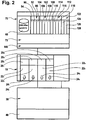
- the visualization controller 30 now generates an in FIG. 2 illustrated visualization program 38 on the basis of the stored in the memory 36 in the form of configuration data machine model 48, the virtual processing units 46 1 to 46 4 on the screen 42 as such together with the predetermined by the control commands 24 1 to 24 4 actions, for example in the form of relative movements of the processing units 46 1 to 46 4 or proper movements of the processing units 46 1 to 46 4 , for example, a rotating driving the workpiece WS in the workpiece spindle 46 1 or a Driving one of the tools WZ or moving a turret of the processing unit 46 3 may include.
- the action control 10 is, as in FIG. 1 represented by a control panel 60 having a third data processing unit 62, which in turn, for example, a processor 64 and a memory 66 for one or more CNC machining program complexes 68 includes.
- a control panel 60 having a third data processing unit 62, which in turn, for example, a processor 64 and a memory 66 for one or more CNC machining program complexes 68 includes.
- the memory 66 therefore, the entire intended for the simulation CNC machining program complex 68 is stored.
- On the third data processing unit 62 runs as a whole designated 70 and in FIG. 2 schematically illustrated operating program, which has a user interface 72 which cooperates with a designated as a whole by 80 machine control panel, for example, a conventional keypad 82 and rows 84 and 86 of function keys 88 1 to 88 16 includes.
- the machine control panel 80 is preferably associated with a display panel 90, which allows the display of information determined by the operating program 70.
- the display panel 90 is controlled by the user interface 72.
- the operating program 70 includes, for example, a in FIG. 2 as a whole, program management function designated by 92 capable of workpiece-managing the CNC machining program complex 68 stored in the memory 66, that is, the program management function 92 manages the individual part programs 20 of the CNC machining program complex 68 to be a workpiece WS belonging parts programs 20 are processed according to their functional identity.
- a transfer mode 94 of the program management function 92 provides that the part programs 20 belonging to the same workpiece are transferred in their functional relationship from the operator control 60 to the action controller 10 for simulation of the machining of this workpiece WS and are handed over to the control program 18, ie, for example the individual channels 22 of the control program 18 are assigned functionally correct and activated accordingly.
- the transfer function 94 is also able to transfer, for example, after completion of the simulation of a machining, the parts program 20 associated with the individual workpiece WS, in turn, from the action control 10 to the operator control 60 and in connection with the respective workpiece WS in the Store memory 66.
- the program management function 92 additionally includes, for example, a backup mode 96 which, for example, is capable of initiating an external backup of the workpiece-related part programs.
- Another mode of the program management function 92 is, for example, still a start / stop mode 98, in which the program management function 92 of the operating program 70 directly intervenes in the action control 10 to start or stop the individual part programs 20 for execution according to a predefined key.
- start / stop mode 98 can also be used directly to start and stop individual part programs 20 independently of the predefined key for execution, for example due to the actuation of one of the function keys 88 of the machine control panel 80.
- the function key 88 1 can be used to start a selected part program and the function key 88 2 can be used to stop a selected part program.
- the operating program 70 for example, still a program processing function 102, with which various interventions in the CNC machining program complex 68 are possible.
- a program creation mode 104 provides that program creation by inputting CNC sets or program correction by insertion or deletion of CNC sets is possible through the machine control panel 80, such as the keypad 82.
- the program processing function 102 also includes, for example, an input mode 106 for input of correction values, for example for operating parameters or positions of the processing units 46.
- Another mode of the program processing function 102 is, for example, an input mode 108 for tools, which allows tools 46 to be assigned to the individual processing units 46, with the assignment at the same time being transferred to the CNC machining program complex 68 tool parameters for these tools WZ.
- an input mode 110 still provides the possibility of entering correction values for selected tools WZ.
- an advantageous embodiment of the operating program 70 according to the invention also includes an analysis function 112, which serves to detect errors in the CNC machining program complex.
- the analysis function 112 provides a multitude of possibilities which facilitate the finding of program errors, in particular in the course of the simulation.
- the analysis function 112 preferably comprises an identification mode 114 for a currently processed NC sentence with which this NC sentence, which is currently being processed by the action control in one of the channels 22, can be marked in order to recognize it later.
- the analysis function 112 preferably includes a display mode 116, with which it is able to display the at least one currently active program command. That is, in this case, the analysis function 112 is able to determine which program command of one of the part programs 20 in the action controller 10 is active and leads to an action of one of the processing units 46.
- a position display mode 118 of the analysis function 112 is provided, which allows to display an axis position of at least one of the processing units 46, that is the position in which this at least one of the virtual processing units 46 is relative to the remaining virtual processing units.
- the advantage of the operating program 70 according to the invention is to be seen in that it does not manage individual parts programs due to the workpiece-related program management function 92, that is stores, transfers or backs up, but always all to a workpiece WS belonging part programs, in particular with tool data, zero offsets and other parameters relevant to the production of a workpiece WS, manages, so that in contrast to the previously known simulation systems, the part programs must not be individually transferred, loaded and managed by the operator.
- start / stop mode 98 which can be activated by manual operation of one of the function keys 88, also makes it possible to start or stop the part programs for execution according to a predefined key or to select and activate part programs 20 by manual operation of one of the function keys 88.
- simulation system according to the invention with the program processing function 102 in the program creation mode 104 allows the creation of elements of part programs or of entire parts programs.
- correction value input mode 106 still provides the possibility of entering and correcting, for example, parameters of the virtual processing units 46.
- the input mode 110 for tool offsets also provides the additional option of correcting tool dimensions already in the simulation system and thus immediately generating part programs that are already executable on the machine tool in the simulation system, or vice versa, to adopt part programs running in the machine tool to the simulation system and to do so check and change if necessary.
- the analysis function 112 still provides the possibility of simulating not only the CNC machining program complex 68 in the simulation system but, in the event of any errors, analyzing it with the greatest possible support for the operator.
- identification mode 114 makes it possible to identify the currently processed NC block by marking or marking in the visual analysis of the simulation of the machining of the workpiece WS upon detection of an error, and thus very quickly to find the error in the respective part program.
- the display mode 116 of the analysis function 112 it is also possible to display the at least one currently active program command or several program commands active at the same time as the processing thereof in the display field 90, so that the user of the simulation device is able to recognize which program instructions may possibly be faulty.
- an error indication is further facilitated by the parameter display mode 118, which displays the at least one current axis position of at least one of the virtual processing units 46 and thus facilitates error analysis or troubleshooting.
- Another possible parameter that can be displayed by the parameter display mode 118 would also be a speed of a virtual workpiece spindle.
- Such a special function 122 may include, for example, a driving mode 124, in which the virtual processing units 46 can be moved by actuating input keys 88 along their axes of motion.
- Another possibility is to provide a travel mode 126 or a start-up mode 126, which makes it possible to empty the virtual machine tool 44, that is to remove the workpiece WS, or to move the empty virtual machine tool 44 with a workpiece WS, that is, a virtual processing to start or continue.
- the solution according to the invention thus makes it possible not only to simulate such a special function 122, but also to program these in connection with the simulation and to examine them in connection with the simulation for possible errors.
- the operating program according to the invention is particularly user-friendly, in particular, if it corresponds to the operating program of the real machine tool on which the CNC machining program complex 68 is to be used. In this case, there is no problem for the user or the operator of the simulation system because the operating program 70 of the simulation system has exactly the same functions as the operating program of its real machine tool.
- Another significant advantage is that the operating program 70 does not have to be specially generated for the simulation system according to the invention, but that the operating program of the real machine tool can be taken over directly.
- a particular advantage in terms of user friendliness also exists if the machine control panel 80 of the simulation system according to the invention substantially corresponds to the machine control panel 80 of the real machine tool.
- the local assignment of the individual functions of the operating program 70 to the individual function keys 88 does not necessarily correspond to the assignment of the real machine tool. However, the user-friendliness is further facilitated by the fact that the assignment of the functions of the operating program 70 to the individual function keys 88 is substantially identical to those of the real machine tool.
- the display panel 90 displays the information displayed by the operating program 70 via the user interface 72 in substantially the same way as the display panel 90 of the machine control panel 80 of the real machine tool.
- control program 18 is an independent program, for example a simulated CNC control program, which is foreign to the machine tool.
- an adjustment program 140 is assigned to the operating program 70, which ensures the communication between the operating program 70 and the control program 18 representing a CNC simulation.
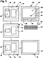
- FIG. 3 and 4 In a second embodiment of a simulation system according to the invention, shown in FIG. 3 and 4 , those components that are identical to those of the first embodiment are provided with the same reference numerals, so that in terms of their description with respect to the comments on the first embodiment reference is made.
- control program 18 in contrast to the first embodiment, in the second embodiment, as in FIG. 4 illustrated, the control program 18 'no CNC replica, but includes the core control program 150 of the real machine tool, which generates as control commands 24 the same control commands as in the real machine tool.
- a program environment 152 for the control program 150 is provided and installed on the first data processing unit 12, which provides the same program environment to the core control program 150 of the real machine tool the real machine tool is the case.
- the operating control 60 is assigned a second visualization unit 160 which, like a conventional computer or PC, is provided with a separate keypad 82 'which corresponds to the usual input keys.
- the machine panel 80 together with its display panel 90' and rows 84 'and 86' of the function keys 88 'is now displayed as a virtual machine control panel 80', with the function keys 88 being operable by a cursor 162, which in turn may be actuated either by the keypad 82 'or a mouse 164 on the image shown is movable.
- control program 18 'in the second exemplary embodiment comprises the core control program 150 of the real machine tool and the operating program 70 corresponds to that of the real machine tool, there is no longer any need to provide a separate adaptation program for communication between the operating program 70 and the control program 18, but instead the adaptation program 140'. is the communication program for the interaction between the operating program 70 and the core control program 150 of the real machine tool used in the real machine tool.
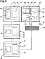
- the third embodiment according to FIG. 5 that only one visualization unit, namely the visualization unit 40 ', is used, on which both the virtual machine tool 44 with the processing units 46 is shown, and superimposed on the virtual machine tool 44, the virtual machine control panel 80', so that the operator on the same Visualization unit 40 'has both the virtual machine tool 44 and the virtual machine control panel 80' are available to run the simulation and act on the operating program 70 in the manner already described in connection with the first embodiment.
- the simulation system is a non-machine tool simulation system, which operates completely independent of the machine tool.
- the simulation system according to the invention is integrated into the operator control 60 'of a real machine tool and the processor 64' is used not only by the operator control 60 ', but also by the action controller 10' and the visualization controller 30 ' Memory 66, 16 and 36 are assigned, which are used in the manner already described for storing the CNC machining program complex 68, or the part programs 20 and the machine model 48.
- the fourth exemplary embodiment of the simulation system uses both the operating program 70 of the real machine tool and the core control program 150 of the real machine tool, it is possible to run a simulation directly on the real machine tool and the part programs using the operating program 70 of the described type CNC machining program complex 68 to manage or edit or analyze.
- FIG. 7 An embodiment of an in FIG. 7
- the production facility shown comprises two production areas 202, 204, wherein in the production area 202 machine tools 206 1 , 206 2 and 206 3 are used, while in the production area 204 machine tools 208 1 , 208 2 and 208 3 are used, each controlled by machine controls 212 1 , 212 2 and 212 3 and 214 1 , 214 2 and 214 3 are used for the actual machining of workpieces.
- the machining of workpieces on these machine tools 206 1 to 206 3 and 208 1 to 208 3 in the production areas 202 and 204 is thereby organized, that is planned and directed, by a production organization system 220, which has a data processing unit 222, with a production organization program 224, with the production organization program 224, for example, the planning of an optimal utilization of the machine tools 206 1 to 206 3 in the production area 202 and the machine tools 208 1 to 208 3 in the production area 204 takes place.
- the production organization program 224 also manages workpiece-related CNC machining program complexes 68, which are stored in a data memory 226 of the Manufacturing organization system 220 are stored, in the data memory 226, the CNC machining program complexes 68 of all intended for manufacturing workpieces are stored, until the respective provided for the workpiece CNC machining program complex 68 in a machine control 212 1 to 212 3 or 214 1 to 214 3 of the machine tools 206 1 to 206 3 or 208 1 to 208 3 is required.
- the manufacturing organization system 220 also includes an organization communication unit 230 provided with a series of communication interfaces 232 1 to 232 8 , the communication interfaces 232 1 to 232 8 being connected to communication units 236 1 to 236 8 via communication paths 234 1 to 234 8 , respectively the communication units 236 2 to 236 7 are assigned to the machine controls 212 1 to 212 3 and 214 1 to 214 3 .
- the organization communication unit 230 operates with an organization communication program 240, and the communication units 236 1 to 236 8 operate with communication programs 242 1 to 242 8 , the organization communication program 240 and the communication programs 242 are coordinated.
- the communication programs 242 in all communication units 236 1 to 236 8 are preferably identical in order to have as little programming effort as possible.
- the communication units 236 1 to 236 8 and the communication interfaces 232 1 to 232 8 are constructed essentially identical, in order to minimize the effort in terms of hardware components.
- the communication units 236 1 and 236 8 are not assigned any machine controls, but rather a simulation system 250 or 260, wherein, for example, the simulation system 250 corresponds to the second exemplary embodiment described above Fig. 3 and 4 is formed while the simulation system 260 according to the above-described, in Fig. 6 illustrated fourth embodiment of the simulation system is formed.
- the operating program 70 is preferably identical to that of the machine controls 212 or 214 of the real machine tools 206 and 208, so that no further adaptation between the communication programs 242 1 and 242 8 and the operating programs 70 is required and also the Communication units 236 1 and 236 8 may be identical to the communication units 236 2 to 236 7 used for the machine controls 212 1 to 212 3 and 214 1 to 214 3 , although the operator controls 60 and 60 'those of the real machine controls 212 1 to 212 3rd and 214 1 to 214 3 of the real machine tools 206 1 to 206 3 and 208 1 to 208 3 .
- the production organization system 220 is thus a production planning level and production management level available to the machining of workpieces on the machine tools 206 1 to 206 3 and 208 1 to 208 3 in the production areas 202 and 204 under optimal optimal utilization of the machine tools 206 1 to 206 3 or 208 1 to 208 3 to organize.
- the CNC machining program complexes 68 for the respective workpieces are managed workpiece-oriented by the production organization program 224 in the data memory 226, so that in a provided on one of the machine tools 206 1 to 206 3 and 208 1 to 208 3 processing a workpiece, the respective machine control 212 1 to 212 3 or 214 1 to 214 3 receives the corresponding CNC machining program complex 68, via the organization communication unit 230 whose organization communication program 240 assigns the corresponding CNC machining program complex 68 to the corresponding communication interface 232 and via this and the communication path 234 the CNC machining program complex 68 of the corresponding communication unit 236, which is associated with the respective machine control 212 or 214, transmitted, so that the respective machine control 212 or 214 the respective CNC machining program complex 68th has to operate the respective machine tool 206 or 208 for machining the workpiece.
- the manufacturing organization system 220 is not limited to merely communicating the CNC machining program complex 68 to the respective machine controller 212 or 214, but it is also possible to add additional control instructions 270 via the organization communication unit 230 to the organization communication program 240 of the respective machine controller 212 of FIG to transfer.
- Such control instructions 270 are, for example, control instructions concerning the program start of the CNC machining program complex 68 on the respective machine control or the number of workpieces to be processed, or even the program stop of the CNC machining program complex 68.
- control instructions 270 may also include the instruction to reload the CNC machining program complex 68 back to the manufacturing organization system 220 after execution of the scheduled processing to store the respective CNC machining program complex 68 in the data storage 226 in that manufacturing organization system.
- the feedback 272 are, for example, feedback regarding processing times or downtimes of the respective machine tool 212 or 214 and feedback regarding the number of machined workpieces and the time required for this purpose.
- the feedback 272 may also include further information about the workpiece machining on the respective machine tool 206 or 208, this information may for example also be information about the performance of the individual machine tools 206 or 208.
- Essential to the manufacturing organization system 220 of the present invention is that the data structure of all the CNC machining program complexes 68 that can be communicated to each of the machine controllers 212 or 214 is the same and the data structure of the control instructions 270 and the feedback 272 are identical, so that the manufacturing organization program 224 both the CNC machining program complexes 68 as well as the control instructions 270 and the feedback 272 can operate in the same way, regardless of which of the machine controls 212 or 214 of the machine tools 206 or 208 they come from.
- each of the production areas 202 and 204 is assigned a machine operator who only has to monitor the function of the machine tools 206, 208 in the case of machine tool-readable CNC machining program complexes, with regard to potentially occurring faults or with regard to interventions in the production sequence necessary for some parts.
- the machine operator in the production areas 202 and 204 still has time during the machining of the workpieces, which is planned and routed essentially via the production organization system 220, still to be used as effectively as possible ,
- At least one simulation system 250 or 260 is associated with the production areas 202 and 204, which then open further actuating possibilities for the machine operator if he does not need 202 or 204 for the production process on the machine tools 206 or 208 of the respective production area becomes.
- the machine operator of the manufacturing area 202 may use the simulation system 250 to create and simulate CNC machining program complexes 68, or to simulate machining program complexes 68 provided by the manufacturing organization system 220 to verify their operability or to orient themselves on what actions the individual processing units are provided by this CNC machining program complex, for example, to prepare the retraction operation of such a CNC machining program complex 68 on one of the machine tools 206 and thereby accelerate and thus save machine times in the machine tools 206.
- the CNC machining program complexes 68 are provided with a property field which can be read by the manufacturing organization program 224.
- the production organization program 224 is thus able to distinguish among the individual CNC machining program complexes 68 between only programmed CNC machining program complexes 68, simulation-tested CNC machining program complexes 68 or CNC machining program complexes 68 already successfully used in the production of machining a workpiece, and thus, for example prior to deployment of such a CNC machining program complex 68 for fabrication on one of the machine tools 206 or 208, to provide that CNC machining program complex 68 to one of the machine operators in the manufacturing areas 202 and 204 on one of the simulation systems 250 or 260, with the task of simulating it Check CNC machining program complex 68 and correct if necessary.
- a tested and possibly corrected CNC machining program complex 68 can in turn be taken over by the production organization system 220 into the data memory 226 and then also to a machine operator, preferably the machine operator of the production area 202 or 204, who has also carried out the simulation, for entering on one of the available standing machine tools 206 or 208 available.
- a CNC machining program complex 68 can already be created and / or simulated with the possibilities of the production device, namely the simulation systems 250 or 260 by a machine operator while the actual machine tools 206 or 208 are not being used and then immediately deployed to control one of the real machine tools 206 or 208, managed by the manufacturing organization program 224, without requiring further steps.
- a significant advantage of the production device is achievable if the communication between the production organization system 220 and the respective simulation system 250 or 260 in exactly the same manner as with the machine controls 212 or 214, so that on the part of the production organization program 224 and the organization communication program 240th , no changes are required as well as on the side of the communication programs which are used for the simulation systems 250 and 260 242 1, 242 8, and thus the hardware and software already used for communication with the machine controllers 212 and 214 can be used, so that the entire Communication between the production organization system 220 and the simulation system 250 or 260 is identical to the communication with the machine controls 212 or 214, and thus eliminates any need for adjustment.
Landscapes
- Engineering & Computer Science (AREA)
- Human Computer Interaction (AREA)
- Manufacturing & Machinery (AREA)
- Physics & Mathematics (AREA)
- General Physics & Mathematics (AREA)
- Automation & Control Theory (AREA)
- Numerical Control (AREA)
Claims (130)
- Dispositif de fabrication pour des pièces à usiner comprenant
au moins une zone de fabrication (202, 204), dans laquelle plusieurs machines-outils (206, 208) pourvues d'une commande de machine (212, 214) sont disposées,
une unité de traitement de données (222), qui est couplée aux commandes de machine (212, 214) des machines-outils (206, 208) par l'intermédiaire d'un chemin de communication (234), et comprenant un programme (224), qui fournit aux machines-outils (206, 208) des paquets d'usinage CNC (68) pour l'usinage de pièces à usiner, caractérisé en ce que l'unité de traitement de données (222) est comprise par un système d'organisation de fabrication (220), qui organise l'usinage de pièces à usiner sur les machines-outils (206, 208) de l'au moins une zone de fabrication (202, 204), en ce que le programme est un programme d'organisation de fabrication (224), en ce qu'au moins un système de simulation (250, 260) est associé au dispositif de fabrication, lequel système de simulation est couplé au système d'organisation de fabrication (220), en ce que le système de simulation (250, 260) représente des actions d'unités d'usinage d'une des machines-outils, en particulier des actions lors de l'usinage d'une pièce à usiner, conformément à un paquet d'usinage CNC (68) au moyen au moins d'une première unité de visualisation (40) sous la forme d'actions d'unités d'usinage (46) virtuelles d'une machine-outil (44) virtuelle, en ce que le système de simulation (250, 260) comprend une commande d'action (10), qui présente au moins une première unité de traitement de données (12), qui détermine, avec un programme de commande (18) traitant des blocs CNC du paquet d'usinage CNC (68), des ordres de commande (24) pour des actions des unités d'usinage (46) virtuelles, en ce que le système de simulation (250, 260) comprend une commande de visualisation (30), qui présente au moins une deuxième unité de traitement de données (32), qui représente sur la première unité de visualisation (40) avec un programme de visualisation (38) à l'aide de données de configuration d'un modèle de machine (48) mémorisé et des ordres de commande (24) déterminées par la commande d'action (10), des actions des unités d'usinage (46) virtuelles, en ce que le système de simulation comprend une commande d'utilisation (60) pourvue d'une troisième unité de traitement de données (62), qui exploite, avec un programme d'utilisation (70), la commande d'action (10), et en ce que le programme d'utilisation (70) présente une fonction d'administration de programme (92), qui transmet, par le paquet d'usinage CNC (68) mémorisé dans une mémoire (66) de la troisième unité de traitement de données (62), aux fins de la mise en oeuvre de ce dernier, à la commande d'action (10) au moins des parties de programme (20) en lien avec la pièce à usiner. - Dispositif de fabrication selon la revendication 1, caractérisé en ce que le dispositif de fabrication présente plusieurs zones de fabrication (202, 204), qui sont couplées au système d'organisation de fabrication (220).
- Dispositif de fabrication selon la revendication 1 ou 2, caractérisé en ce que plusieurs systèmes de simulation (250, 260) sont associés au système d'organisation de fabrication (220).
- Dispositif de fabrication selon l'une quelconque des revendications 1 à 3, caractérisé en ce que le système de simulation (250, 260) est associé à une zone de fabrication (202, 204).
- Dispositif de fabrication selon l'une quelconque des revendications précédentes, caractérisé en ce que respectivement au moins un des systèmes de simulation (250, 260) selon l'une quelconque des revendications précédentes est associé à plusieurs zones de fabrication (202, 204).
- Dispositif de fabrication selon l'une quelconque des revendications précédentes, caractérisé en ce que le chemin de communication (234) entre le système d'organisation de fabrication (220) et l'au moins une commande de machine (212, 214) et le chemin de communication (234) entre le système d'organisation de fabrication (220) et le système de simulation (250, 260) respectif sont configurés de manière identique.
- Dispositif de fabrication selon l'une quelconque des revendications précédentes, caractérisé en ce que le système d'organisation de fabrication (220) fournit au système de simulation (250, 260) des paquets d'usinage CNC (68) pour la simulation d'actions d'unités d'usinage (46) virtuelles sur une machine-outil (44) virtuelle.
- Dispositif de fabrication selon l'une quelconque des revendications, caractérisé en ce que le système d'organisation de fabrication (220) présente une unité de communication d'organisation (230) pourvue au moins d'une interface de communication (232), et en ce que la commande de machine (212, 214) est couplée à l'au moins une interface de communication (232).
- Dispositif de fabrication selon la revendication 7, caractérisé en ce que l'unité de communication d'organisation (230) présente une autre interface de communication (232), à laquelle l'au moins un système de simulation (250, 260) est couplé.
- Dispositif de fabrication selon la revendication 9, caractérisé en ce que l'interface de communication (232) pour l'au moins un système de simulation (250, 260) et l'au moins une interface de communication (232) pour l'au moins une commande de machine (212, 214) sont configurées essentiellement de manière identique.
- Dispositif de fabrication selon l'une quelconque des revendications précédentes, caractérisé en ce que l'unité de communication d'organisation (230) présente un programme de communication d'organisation (240) servant à la communication avec l'au moins une commande de machine (212, 214).
- Dispositif de fabrication selon l'une quelconque des revendications précédentes, caractérisé en ce que l'unité de communication d'organisation (230) présente un programme de communication d'organisation (240) servant à la communication avec le système de simulation (250, 260).
- Dispositif de fabrication selon la revendication 11 ou 12, caractérisé en ce que le programme de communication d'organisation (240) servant à la communication avec l'au moins une commande de machine (212, 214) est essentiellement identique au programme de communication d'organisation (240) servant à la communication avec l'au moins un système de simulation (250, 260).
- Dispositif de fabrication selon l'une quelconque des revendications précédentes, caractérisé en ce qu'une unité de communication (236) comprenant un programme de communication (242) servant à la communication avec le système d'organisation de fabrication (220) est associée à la commande de machine (212, 214) respective.
- Dispositif de fabrication selon l'une quelconque des revendications précédentes, caractérisé en ce qu'une unité de communication (236) comprenant un programme de communication (242) servant à la communication avec le système d'organisation de fabrication (220) est associée au système de simulation (250, 260).
- Dispositif de fabrication selon la revendication 14 ou 15, caractérisé en ce que le programme de communication (242) du système de simulation (250, 260) respectif fonctionne avec des formats de données et des spécifications de données identiques à celles du programme de communication (242) de la commande de machine (212, 214) respective.
- Dispositif de fabrication selon la revendication 16, caractérisé en ce que le programme de communication (242) du système de simulation (250, 260) est essentiellement identique au programme de communication (242) de la commande de machine (212, 214) respective.
- Dispositif de fabrication selon l'une quelconque des revendications précédentes, caractérisé en ce que des paquets d'usinage CNC (68) exécutés par les commandes de machine (212, 214) peuvent être transmis sur le système d'organisation de fabrication (220).
- Dispositif de fabrication selon l'une quelconque des revendications précédentes, caractérisé en ce que des paquets d'usinage CNC (68) simulés par le système de simulation (250, 260) respectif peuvent être transmis sur le système d'organisation de fabrication (220).
- Dispositif de fabrication selon la revendication 18 ou 19, caractérisé en ce que le système d'organisation de fabrication (220) administre des paquets d'usinage CNC (68) transmis par le système de simulation (250, 260) respectif de la même manière que des paquets d'usinage CNC (68) transmis par l'au moins une commande de machine (214, 216).
- Dispositif de fabrication selon l'une quelconque des revendications précédentes, caractérisé en ce que le système d'organisation de fabrication (220) reçoit de l'au moins une commande de machine (212, 214) des retours d'information (272) concernant le traitement du paquet d'usinage CNC (68) respectif dans ladite commande de machine.
- Dispositif de fabrication selon l'une quelconque des revendications précédentes, caractérisé en ce que le système d'organisation de fabrication (220) reçoit du système de simulation (250, 260) respectif des retours d'information (272) concernant le traitement du paquet d'usinage CNC (68) respectif.
- Dispositif de fabrication selon la revendication 21 ou 22, caractérisé en ce que les retours d'information (272) de l'au moins une commande de machine (212, 214) et les retours d'information du système de simulation (250, 260) respectif présentent une structure essentiellement identique.
- Dispositif de fabrication selon l'une quelconque des revendications précédentes, caractérisé en ce que le système d'organisation de fabrication (220) de l'au moins une commande de machine (212, 214) transmet des instructions de commande (270).
- Dispositif de fabrication selon l'une quelconque des revendications précédentes, caractérisé en ce que le système d'organisation de production (220) transmet au système de simulation (250, 260) respectif des instructions de commande (270).
- Dispositif de fabrication selon la revendication 24 ou 25, caractérisé en ce que les instructions de commande (270) pour l'au moins une commande de machine (212, 214) et les instructions de commande (270) pour le système de simulation (250, 260) respectif présentent une structure essentiellement identique.
- Dispositif de fabrication selon l'une quelconque des revendications précédentes, caractérisé en ce que le système d'organisation de fabrication (220) présente une mémoire de données (226) pour les paquets d'usinage CNC (68).
- Dispositif de fabrication selon l'une quelconque des revendications précédentes, caractérisé en ce que les paquets d'usinage CNC (68) pour le programme d'organisation de fabrication (224) sont identifiables par un champ de propriétés comme étant non contrôlés ou contrôlés par simulation.
- Dispositif de fabrication selon la revendication 28, caractérisé en ce que les paquets d'usinage CNC (68) pour le programme d'organisation de fabrication (224) sont identifiables par le champ de propriétés comme étant à production contrôlée.
- Dispositif de fabrication selon l'une quelconque des revendications précédentes, caractérisé en ce que le système d'organisation de fabrication (220) administre les paquets d'usinage CNC (68) en lien avec les pièces à usiner.
- Dispositif de fabrication selon l'une quelconque des revendications précédentes, caractérisé en ce qu'un panneau de commande de machine (80) est associé à la commande d'utilisation (60) du système de simulation.
- Dispositif de fabrication selon la revendication 31, caractérisé en ce que le fonctionnement du programme d'utilisation (70) peut être commandé par l'intermédiaire de fonctions (92, 102, 112, 122) pouvant être appelées au moyen du panneau de commande de machine (80).
- Dispositif de fabrication selon la revendication 32, caractérisé en ce que le panneau de commande de machine (80) présente des éléments de saisie (88) manuelle pour une activation de diverses fonctions (92, 102, 112, 122) du programme d'utilisation (70).
- Dispositif de fabrication selon l'une quelconque des revendications 31 à 33, caractérisé en ce que le panneau de commande de machine (80) présente des éléments de saisie (88) manuelle servant à agir sur le paquet d'usinage CNC (68).
- Dispositif de fabrication selon l'une quelconque des revendications 31 à 34, caractérisé en ce que le panneau de commande de machine (80) présente des éléments de saisie (88) manuelle servant à utiliser des fonctions de la commande d'action (10).
- Dispositif de fabrication selon la revendication 35, caractérisé en ce que le panneau de commande de machine (80) comprend des éléments de saisie (88) manuelle pour le démarrage/l'arrêt d'au moins un programme partiel (20) dans la commande d'action (10).
- Dispositif de fabrication selon l'une quelconque des revendications 31 à 36, caractérisé en ce que la commande d'utilisation (60) est couplée à un champ d'affichage (90) du panneau de commande de machine (80), et en ce que la commande d'utilisation (60) du programme d'utilisation (70) représente sur le champ d'affichage (90) des informations prévues aux fins de l'affichage pour un opérateur.
- Dispositif de fabrication selon l'une quelconque des revendications 31 à 37, caractérisé en ce que le panneau de commande de machine est un panneau de commande de machine (80') virtuel représenté sur une unité de visualisation (160, 40').
- Dispositif de fabrication selon la revendication 38, caractérisé en ce que les éléments de saisie (88') manuelle du panneau de commande de machine (80') virtuel peuvent être actionnés manuellement par un curseur (162) de l'unité de visualisation (160, 40').
- Dispositif de fabrication selon l'une quelconque des revendications précédentes, caractérisé en ce que la fonction d'administration de programme (92) du programme d'utilisation (70) administre en lien avec les pièces à usiner des programmes partiels (20) du paquet d'usinage CNC (68).
- Dispositif de fabrication selon l'une quelconque des revendications précédentes, caractérisé en ce que la fonction d'administration de programme (92) du programme d'utilisation (70) mémorise en lien avec les pièces à usiner des programmes partiels (20) du paquet d'usinage CNC (68).
- Dispositif de fabrication selon l'une quelconque des revendications précédentes, caractérisé en ce que la fonction d'administration de programme (92) du programme d'utilisation (70) protège en lien avec les pièces à usiner des programmes partiels (20) du paquet d'usinage CNC (68).
- Dispositif de fabrication selon l'une quelconque des revendications précédentes, caractérisé en ce que la fonction d'administration de programme (92) du programme d'utilisation (70) transmet des programmes partiels (20) du paquet d'usinage CNC (68) à la commande d'action (10) en lien avec les pièces à usiner.
- Dispositif de fabrication selon l'une quelconque des revendications précédentes, caractérisé en ce que la fonction d'administration de programme (92) du programme d'utilisation (70) répartit sur divers canaux (22) de la commande d'action (10) et active en lien avec les pièces à usiner des programmes partiels (20) du paquet d'usinage CNC (68).
- Dispositif de fabrication selon l'une quelconque des revendications précédentes, caractérisé en ce que le programme d'utilisation (70) comprend une fonction d'usinage de programme (102), à l'aide de laquelle le paquet d'usinage CNC (68) peut être modifié en accédant au moins à des parties de programme (20) du paquet d'usinage CNC (68).
- Dispositif de fabrication selon la revendication 45, caractérisé en ce que la fonction d'usinage de programme (102) comprend un mode de création de programme (104).
- Dispositif de fabrication selon la revendication 45 ou 46, caractérisé en ce que la fonction d'usinage de programme (102) comprend un mode de saisie (106) pour des valeurs de correction.
- Dispositif de fabrication selon l'une quelconque des revendications 45 à 47, caractérisé en ce que la fonction d'usinage de programme (102) prend en charge la modification de programme en toute autonomie dans le paquet d'usinage CNC (68).
- Dispositif de fabrication selon l'une quelconque des revendications 45 à 48, caractérisé en ce que la fonction d'usinage de programme (102) recharge les programmes partiels (20) présents dans la commande d'action (10) en toute autonomie dans la commande d'utilisation (60) aux fins de la modification.
- Dispositif de fabrication selon l'une quelconque des revendications 45 à 49, caractérisé en ce que la fonction d'usinage de programme (102) comprend un mode de saisie (108) pour des outils (WZ).
- Dispositif de fabrication selon l'une quelconque des revendications 45 à 50, caractérisé en ce que la fonction d'usinage de programme (102) comprend un mode de saisie (110) pour des corrections d'outil.
- Dispositif de fabrication selon l'une quelconque des revendications précédentes, caractérisé en ce que le programme d'utilisation (70) comprend une fonction d'analyse (112).
- Dispositif de fabrication selon la revendication 52, caractérisé en ce qu'un bloc NC usiné instantanément dans la commande d'action (10) peut être identifié dans un mode d'identification (114) de la fonction d'analyse (112).
- Dispositif de fabrication selon la revendication 52 ou 53, caractérisé en ce que l'au moins un ordre de programme actif au moment t peut être affiché dans un mode d'affichage (116) de la fonction d'analyse (112).
- Dispositif de fabrication selon l'une quelconque des revendications 52 à 54, caractérisé en ce qu'au moins un paramètre au moins d'une des unités d'usinage (46) virtuelles peut être affiché dans un mode d'affichage de paramètre (118) de la fonction d'analyse (112).
- Dispositif de fabrication selon l'une quelconque des revendications précédentes, caractérisé en ce que le programme d'utilisation (70) correspond au programme d'utilisation de la machine-outil réelle.
- Dispositif de fabrication selon la revendication 56, caractérisé en ce que le programme d'utilisation (70) servant à la communication avec le programme de commande (18) interagit avec un programme d'adaptation (140).
- Dispositif de fabrication selon l'une quelconque des revendications précédentes, caractérisé en ce que le programme de commande (18) de la commande d'action (10) est un programme de commande étranger à la machine-outil.
- Dispositif de fabrication selon la revendication 58, caractérisé en ce que le programme d'adaptation (140) adapte le programme d'utilisation (70) au programme de commande (18) étranger à la machine-outil.
- Dispositif de fabrication selon l'une quelconque des revendications 1 à 59, caractérisé en ce que le programme de commande (18) de la commande d'action (10) comprend le programme de commande centrale (150) de la machine-outil afin de générer des ordres de commande (24).
- Dispositif de fabrication selon la revendication 60, caractérisé en ce que la première unité de traitement de données (12) présente un environnement de programme (152), sur lequel le programme de commande centrale (150) de la machine-outil réelle fonctionne et génère des ordres de commande (24), qui correspondent aux ordres de commande de la machine-outil réelle.
- Dispositif de fabrication selon la revendication 60 ou 61, caractérisé en ce que le programme d'adaptation (140') correspond au programme de communication de la commande d'utilisation (60) réelle de la machine-outil.
- Dispositif de fabrication selon l'une quelconque des revendications précédentes, caractérisé en ce que la première unité de traitement de données (12) et la deuxième unité de traitement de données (32) fonctionnent avec le même processeur (64).
- Dispositif de fabrication selon l'une quelconque des revendications précédentes, caractérisé en ce que la première, la deuxième et la troisième unité de traitement de données (12, 32, 62) fonctionnent avec le même processeur (64).
- Dispositif de fabrication selon l'une quelconque des revendications précédentes, caractérisé en ce que la première unité de traitement de données (12) et/ou la deuxième unité de traitement de données (32) et/ou la troisième unité de traitement de données (62) sont des unités de traitement de données étrangères à la machine-outil.
- Dispositif de fabrication selon l'une quelconque des revendications précédentes, caractérisé en ce que la troisième unité de traitement de données (62) utilise le processeur (64) associé à la commande d'utilisation (60) de la machine-outil réelle.
- Dispositif de fabrication selon l'une quelconque des revendications précédentes, caractérisé en ce que la deuxième unité de traitement de données (32) utilise le processeur (64) associé à la commande d'utilisation (60) de la machine-outil réelle.
- Dispositif de fabrication selon l'une quelconque des revendications précédentes, caractérisé en ce que la première unité de traitement de données (12) utilise le processeur (64) associé à la commande d'utilisation (60) de la machine-outil réelle.
- Dispositif de fabrication selon l'une quelconque des revendications précédentes, caractérisé en ce que l'unité de visualisation (40) pour la représentation des unités d'usinage (46) virtuelles et l'unité de visualisation (160) pour la représentation du panneau de commande de machine (80') virtuel sont des unités séparées.
- Dispositif de fabrication selon l'une quelconque des revendications précédentes, caractérisé en ce que l'unité de visualisation (40) pour la représentation des unités d'usinage (46) virtuelles et l'unité de visualisation pour la représentation du panneau de commande de machine (80') virtuel sont identiques.
- Dispositif de fabrication selon la revendication 70, caractérisé en ce que la représentation des actions des unités d'usinage (46) virtuelles et la représentation du panneau de commande de machine (80') virtuel se font au moins en partie de manière superposée.
- Procédé de fonctionnement d'un dispositif de fabrication pour des pièces à usiner, comprenant
au moins une zone de fabrication (202, 204), dans laquelle plusieurs machines-outils (206, 208) pourvues d'une commande de machine (212, 214) sont disposées, caractérisé en ce qu'un système d'organisation de fabrication (220) avec un programme d'organisation de fabrication (224) communique avec les commandes de machine (212, 214) des machines-outils (206, 208) par l'intermédiaire d'un chemin de communication (234), en ce que le programme d'organisation de fabrication (224) organise l'usinage de pièces à usiner sur les machines-outils (206, 208) de l'au moins une zone de fabrication (202, 204), des paquets d'usinage CNC (68) pour l'usinage de pièces à usiner étant fournis par le programme d'organisation de fabrication (224) à l'au moins une machine-outil (206, 208), en ce qu'est fourni, afin de faire fonctionner le dispositif de fabrication, au moins un procédé servant à faire fonctionner un système de simulation (250, 260), lequel interagit avec le programme d'organisation de fabrication (224), en ce que le procédé servant à faire fonctionner un système de simulation représente des actions d'unités d'usinage d'une des machines-outils, en particulier d'actions lors de l'usinage d'une pièce à usiner, conformément à un paquet d'usinage CNC (68) au moyen au moins d'une première unité de visualisation (40) sous la forme d'actions d'unités d'usinage (46) virtuelles d'une machine-outil (44) virtuelle, en ce que lors du procédé une commande d'action (10) détermine, avec un programme de commande (18) traitant des blocs CNC du paquet d'usinage CNC (68), des ordres de commande (24) pour des actions des unités d'usinage (46) virtuelles, en ce que lors du procédé, une commande de visualisation (30) représente, avec un programme de visualisation (38) à l'aide de données de configuration d'un modèle de machine (48) mémorisé et des ordres de commande (24) déterminés par la commande d'action (10), des actions des unités d'usinage (46) virtuelles sur la première unité de visualisation (40), en ce qu'une commande d'utilisation (60) comprenant un programme d'utilisation (70) fait fonctionner la commande d'action (10), et en ce que le programme d'utilisation (70) comprenant une fonction d'administration de programme (92) du paquet d'usinage CNC (68) mémorisé transmet, aux fins de la mise en oeuvre de ce dernier, à la commande d'action (10) au moins des parties de programme (20) de ce dernier en lien avec les pièces à usiner. - Procédé selon la revendication 72, caractérisé en ce que plusieurs zones de fabrication (202, 204) sont couplées au programme d'organisation de fabrication (224).
- Procédé selon la revendication 72 ou 73, caractérisé en ce que le programme d'organisation de fabrication (224) coopère avec plusieurs systèmes de simulation (250, 260).
- Procédé selon l'une quelconque des revendications 72 à 74, caractérisé en ce que le système de simulation (250, 260) est associé à une zone de fabrication (202, 204).
- Procédé selon l'une quelconque des revendications 72 à 75, caractérisé en ce que respectivement au moins un des systèmes de simulation (250, 260) selon l'une quelconque des revendications 1 et 31 à 71 est associé à plusieurs zones de fabrication (202, 204).
- Procédé selon l'une quelconque des revendications 72 à 76, caractérisé en ce que la communication entre le programme d'organisation de fabrication (224) et l'au moins une commande de machine (212, 214) et la communication entre le système d'organisation de fabrication (220) et le système de simulation (250, 260) respectif sont mises en oeuvre essentiellement de manière identique.
- Procédé selon l'une quelconque des revendications 72 à 77, caractérisé en ce que des paquets d'usinage CNC (68) pour la simulation d'actions d'unités d'usinage (46) virtuelles sur une machine-outil (44) virtuelle sont fournis au système de simulation (250, 260) par le programme d'organisation de fabrication (224).
- Procédé selon l'une quelconque des revendications 72 à 78, caractérisé en ce qu'un programme de communication d'organisation (240) est utilisé aux fins de la communication avec l'au moins une commande de machine (212, 214).
- Procédé selon l'une quelconque des revendications 72 à 79, caractérisé en ce qu'un programme de communication d'organisation (240) est utilisé aux fins de la communication avec le système de simulation (250, 260).
- Procédé selon la revendication 79 ou 80, caractérisé en ce que le programme de communication d'organisation (240) servant à la communication avec l'au moins une commande de machine (212, 214) est essentiellement identique au programme de communication d'organisation (240) servant à la communication avec l'au moins un système de simulation (250, 260).
- Procédé selon l'une quelconque des revendications 72 à 81, caractérisé en ce qu'un programme de communication (242) servant à la communication avec le programme d'organisation de fabrication (224) est utilisé par la commande de machine (212, 214) respective.
- Procédé selon l'une quelconque des revendications 72 à 82, caractérisé en ce qu'un programme de communication (242) servant à la communication avec le système d'organisation de fabrication (220) est utilisé par le système de simulation (250, 260).
- Procédé selon la revendication 82 ou 83, caractérisé en ce que le programme de communication (242) du système de simulation (250, 260) respectif fonctionne avec des formats de données et des spécifications de données identiques à ceux du programme de communication (242) de la commande de machine (212, 214) respective.
- Procédé selon la revendication 84, caractérisé en ce que le programme de communication (242) du système de simulation (250, 260) est essentiellement identique au programme de communication (242) de la commande de machine (212, 214) respective.
- Procédé selon l'une quelconque des revendications 72 à 85, caractérisé en ce que des paquets d'usinage CNC (68) exécutés par les commandes de machine (212, 214) sont transmis au programme d'organisation de fabrication (224).
- Procédé selon l'une quelconque des revendications 72 à 86, caractérisé en ce que des paquets d'usinage CNC (68) simulés par le système de simulation (250, 260) respectif sont transférés au programme de fabrication (224).
- Procédé selon la revendication 86 ou 87, caractérisé en ce que des paquets d'usinage CNC (68) transmis par le système de simulation (250, 260) respectif sont administrés par le programme d'organisation de fabrication (224) de la même manière que des paquets d'usinage CNC (68) transmis par l'au moins une commande de machine (214, 216).
- Procédé selon l'une quelconque des revendications 72 à 88, caractérisé en ce que des retours d'information (272) concernant l'exécution du paquet d'usinage CNC (68) respectif sont transférés par l'au moins une commande de machine (212, 214) au programme d'organisation de fabrication (224).
- Procédé selon l'une quelconque des revendications 72 à 89, caractérisé en ce que des retours d'information (272) concernant l'exécution du paquet d'usinage CNC (68) respectif sont transférés par le système de simulation (250, 260) respectif au programme d'organisation de fabrication (224).
- Procédé selon la revendication 89 ou 90, caractérisé en ce que les retours d'information (272) de l'au moins une commande de machine (212, 214) et les retours d'information du système de simulation (250, 260) respectif présentent une structure essentiellement identique.
- Procédé selon l'une quelconque des revendications 72 à 91, caractérisé en ce que des instructions de commande (270) sont transmises par le programme d'organisation de fabrication (224) de l'au moins une commande de machine (212, 214).
- Procédé selon l'une quelconque des revendications 72 à 92, caractérisé en ce que des instructions de commande (270) sont transmises par le programme d'organisation de fabrication (224) au système de simulation (250, 260) respectif.
- Procédé selon la revendication 91 ou 92, caractérisé en ce que les instructions de commande (270) pour l'au moins une commande de machine (212, 214) et les instructions de commande (270) pour le système de simulation (250, 260) respectif présentent une structure essentiellement identique.
- Procédé selon l'une quelconque des revendications 72 à 94, caractérisé en ce que les paquets d'usinage CNC (68) pour le programme d'organisation de fabrication (224) sont identifiés par un champ de propriétés comme étant non contrôlés ou contrôlés par simulation.
- Procédé selon la revendication 95, caractérisé en ce que les paquets d'usinage CNC (68) pour le programme d'organisation de fabrication (224) sont identifiés par le champ de propriétés comme étant à production contrôlée.
- Procédé selon l'une quelconque des revendications 72 à 96, caractérisé en ce que les paquets d'usinage CNC (68) sont administrés en lien avec les pièces à usiner par le programme d'organisation de fabrication (224).
- Procédé selon l'une quelconque des revendications précédentes, caractérisé en ce que le fonctionnement du programme d'utilisation (70) est commandé par l'intermédiaire de fonctions (92, 102, 112, 122) pouvant être appelées au moyen d'un panneau de commande de machine (80).
- Procédé selon l'une quelconque des revendications précédentes, caractérisé en ce que diverses fonctions (92, 102, 112, 122) du programme d'utilisation (70) sont activées par l'intermédiaire d'éléments de saisie (88) manuelle du panneau de commande de machine (80).
- Procédé selon l'une quelconque des revendications précédentes, caractérisé en ce qu'un effet sur le paquet d'usinage CNC (68) se fait par l'intermédiaire d'éléments de saisie (88) manuelle.
- Procédé selon l'une quelconque des revendications précédentes, caractérisé en ce que des fonctions de la commande d'action (10) sont utilisées par l'intermédiaire d'éléments de saisie (88) manuelle.
- Procédé selon la revendication 101, caractérisé en ce qu'un démarrage/arrêt d'au moins un programme partiel (20) se fait dans la commande d'action (10) par l'intermédiaire d'éléments de saisie (88) manuelle.
- Procédé selon l'une quelconque des revendications précédentes, caractérisé en ce que la commande d'utilisation (60) du programme d'utilisation (70) représente sur un champ d'affichage (90) du panneau de commande de machine (80) des informations destinées à l'affichage pour un opérateur.
- Procédé selon l'une quelconque des revendications précédentes, caractérisé en ce que le panneau de commande de machine est représenté en tant que panneau de commande de machine (80') virtuel sur une unité de visualisation (160, 40').
- Procédé selon la revendication 104, caractérisé en ce que les éléments de saisie (88') manuelle du panneau de commande de machine (80') virtuel sont actionnés manuellement par un curseur (162) de l'unité de visualisation (160, 40').
- Procédé selon l'une quelconque des revendications précédentes, caractérisé en ce que des programmes partiels (20) du paquet d'usinage CNC (68) sont administrés en lien avec les pièces à usiner par la fonction d'administration de programme (92) du programme d'utilisation (70).
- Procédé selon l'une quelconque des revendications précédentes, caractérisé en ce que des programmes partiels (20) du paquet d'usinage CNC (68) sont mémorisés en lien avec les pièces à usiner par la fonction d'administration de programme (92) du programme d'utilisation (70).
- Procédé selon l'une quelconque des revendications précédentes, caractérisé en ce que des programmes partiels (20) du paquet d'usinage CNC (68) sont protégés en lien avec les pièces à usiner par la fonction d'administration de programme (92) du programme d'utilisation (70).
- Procédé selon l'une quelconque des revendications précédentes, caractérisé en ce que des programmes partiels (20) du paquet d'usinage CNC (68) sont transmis en lien avec les pièces à usiner à la commande d'action (10) par la fonction d'administration de programme (92) du programme d'utilisation (70).
- Procédé selon l'une quelconque des revendications précédentes, caractérisé en ce que des programmes partiels (20) du paquet d'usinage CNC (68) sont répartis sur divers canaux (22) de la commande d'action (10) et sont activés, en lien avec les pièces à usiner, par la fonction d'administration de programme (92) du programme d'utilisation (70).
- Procédé selon l'une quelconque des revendications précédentes, caractérisé en ce que le programme d'utilisation (70) comprend une fonction d'usinage de programme (102), à l'aide de laquelle le paquet d'usinage CNC (68) peut être modifié par un accès au moins à des parties de programme (20) du paquet d'usinage CNC (68).
- Procédé selon la revendication 111, caractérisé en ce qu'au moins des parties de programme (20) sont créées avec un mode de création de programme (104) de la fonction d'usinage de programme (102).
- Procédé selon la revendication 111 ou 112, caractérisé en ce que des valeurs de correction sont saisies avec un mode de saisie (106) de la fonction d'usinage de programme (102).
- Procédé selon l'une quelconque des revendications 111 à 113, caractérisé en ce qu'une modification de programme est entreprise en toute autonomie dans le paquet d'usinage CNC (68) par la fonction d'usinage de programme (102).
- Procédé selon l'une quelconque des revendications 111 à 114, caractérisé en ce que les programmes partiels (20) présents dans la commande d'action (10) sont rechargés en toute autonomie dans la commande d'utilisation (60) aux fins de la modification par la fonction d'usinage de programme (102).
- Procédé selon l'une quelconque des revendications 111 à 115, caractérisé en ce que la saisie est effectuée avec un mode de saisie (108) de la fonction d'usinage de programme (102).
- Procédé selon l'une quelconque des revendications 111 à 116, caractérisé en ce que des corrections d'outil sont effectuées avec un mode de saisie (110) de la fonction d'usinage de programme (102).
- Procédé selon l'une quelconque des revendications précédentes, caractérisé en ce qu'une analyse de programme est effectuée avec une fonction d'analyse (112) du programme d'utilisation (70).
- Procédé selon la revendication 118, caractérisé en ce qu'un bloc NC usiné de manière instantanée dans la commande d'action (10) est identifié avec un mode d'identification (114) de la fonction d'analyse (112).
- Procédé selon la revendication 118 ou 119, caractérisé en ce que l'au moins un ordre de programme actif au moment t est affiché avec un mode d'affichage (116) de la fonction d'analyse (112).
- Procédé selon l'une quelconque des revendications 118 à 120, caractérisé en ce qu'au moins un paramètre au moins d'une des unités de traitement (46) virtuelles est affiché avec un mode d'affichage de paramètre (118) de la fonction d'analyse (112).
- Procédé selon l'une quelconque des revendications précédentes, caractérisé en ce que le programme d'utilisation (70) correspond au programme d'utilisation de la machine-outil réelle.
- Procédé selon la revendication 122, caractérisé en ce que le programme d'utilisation (70) communique avec le programme de commande (18) par l'intermédiaire d'un programme d'adaptation (140).
- Procédé selon l'une quelconque des revendications précédentes, caractérisé en ce que le programme de commande (18) de la commande d'action (10) est un programme de commande étranger à la machine-outil.
- Procédé selon l'une quelconque des revendications précédentes, caractérisé en ce que le programme de commande (18) de la commande d'action (10) fonctionne avec le programme de commande centrale (150) de la machine-outil réelle servant à générer des ordres de commande (24).
- Procédé selon la revendication 125, caractérisé en ce que le programme de commande (18') comprend un environnement de programme (152), sur lequel le programme de commande centrale (150) de la machine-outil réelle fonctionne et génère des ordres de commande (24), qui correspondent aux ordres de commande de la machine-outil réelle.
- Procédé selon l'une quelconque des revendications précédentes, caractérisé en ce que le programme de commande (70) s'exécute sur le processeur (64) associé à la commande d'utilisation (60) de la machine-outil réelle.
- Procédé selon l'une quelconque des revendications précédentes, caractérisé en ce que le programme de visualisation (38) s'exécute sur le processeur (64) associé à la commande d'utilisation (60) de la machine-outil réelle.
- Procédé selon l'une quelconque des revendications précédentes, caractérisé en ce que le programme de commande (18') s'exécute sur le processeur (64) associé à la commande d'utilisation (60) de la machine-outil réelle.
- Procédé selon l'une quelconque des revendications précédentes, caractérisé en ce que des actions des unités d'usinage (46) virtuelles et le panneau de commande de machine (80') virtuel sont représentés au moins en partie de manière superposée.
Applications Claiming Priority (1)
| Application Number | Priority Date | Filing Date | Title |
|---|---|---|---|
| DE102005045028A DE102005045028A1 (de) | 2005-09-12 | 2005-09-12 | Simulationssystem |
Publications (3)
| Publication Number | Publication Date |
|---|---|
| EP1762919A2 EP1762919A2 (fr) | 2007-03-14 |
| EP1762919A3 EP1762919A3 (fr) | 2008-11-19 |
| EP1762919B1 true EP1762919B1 (fr) | 2017-03-01 |
Family
ID=37460110
Family Applications (1)
| Application Number | Title | Priority Date | Filing Date |
|---|---|---|---|
| EP06018827.3A Active EP1762919B1 (fr) | 2005-09-12 | 2006-09-08 | Système de simulation |
Country Status (3)
| Country | Link |
|---|---|
| US (1) | US7684890B2 (fr) |
| EP (1) | EP1762919B1 (fr) |
| DE (1) | DE102005045028A1 (fr) |
Families Citing this family (26)
| Publication number | Priority date | Publication date | Assignee | Title |
|---|---|---|---|---|
| IL184021A (en) * | 2006-07-18 | 2012-07-31 | Erowa Ag | System for the exchange of information between machining apparatus and a transfer device |
| US8024068B2 (en) * | 2006-08-04 | 2011-09-20 | Hurco Companies, Inc. | Machine tool control system |
| US8725283B2 (en) * | 2006-08-04 | 2014-05-13 | Hurco Companies, Inc. | Generalized kinematics system |
| DE102006043390B4 (de) * | 2006-09-15 | 2010-05-27 | Dmg Electronics Gmbh | Vorrichtung und Verfahren zur Simulation eines Ablaufs zur Bearbeitung eines Werkstücks an einer Werkzeugmaschine |
| DE102006059430A1 (de) * | 2006-12-15 | 2008-06-19 | Robert Bosch Gmbh | Automatisierte Erstellung und Adaption eines Maschinen- oder Anlagenmodells |
| US9459616B2 (en) * | 2007-08-03 | 2016-10-04 | Hurco Companies, Inc. | Universal conversational programming for machine tool systems |
| US8844104B2 (en) * | 2009-04-22 | 2014-09-30 | Hurco Companies, Inc. | Multi-zone machine tool system |
| DE102007045620A1 (de) | 2007-09-14 | 2009-04-16 | Index-Werke Gmbh & Co. Kg Hahn & Tessky | Werkzeugmaschine |
| DE102007045595A1 (de) * | 2007-09-14 | 2009-03-26 | Index-Werke Gmbh & Co. Kg Hahn & Tessky | Verfahren und virtuelle Werkzeugmaschine zur Darstellung von Aktionen einer realen Werkzeugmaschine |
| DE102007045593A1 (de) | 2007-09-14 | 2009-03-26 | Index-Werke Gmbh & Co. Kg Hahn & Tessky | Virtuelle Werkzeugmaschine zur Darstellung von Aktionen von Bearbeitungseinheiten einer realen Werkzeugmaschine |
| WO2009076987A1 (fr) * | 2007-12-17 | 2009-06-25 | Siemens Aktiengesellschaft | Système et procédé pour simuler l'exécution d'un programme de commande |
| US8577655B2 (en) * | 2008-06-26 | 2013-11-05 | Siemens Product Lifecycle Management Software Inc. | System and method for constructing virtual NC controllers for machine tool simulation |
| DE102009004285A1 (de) | 2008-06-27 | 2009-12-31 | Robert Bosch Gmbh | Verfahren und Vorrichtung zur Optimierung, Überwachung oder Analyse eines Prozesses |
| JP5108662B2 (ja) * | 2008-07-07 | 2012-12-26 | 株式会社森精機製作所 | 加工プログラム処理装置 |
| DE102009029064A1 (de) * | 2008-09-05 | 2010-04-01 | Mori Seiki Co., Ltd., Yamatokoriyama-shi | Verfahren und Vorrichtung zur Bearbeitungszustandsüberwachung |
| US8688258B2 (en) * | 2008-09-11 | 2014-04-01 | Rockwell Automation Technologies, Inc. | Method of controlling a machine tool |
| DE102009023648A1 (de) | 2009-05-26 | 2010-12-02 | Index-Werke Gmbh & Co. Kg Hahn & Tessky | Steuerungssystem |
| US8666533B2 (en) * | 2009-10-09 | 2014-03-04 | Siemens Product Lifecycle Management Software Inc. | System, method, and interface for virtual commissioning of press lines |
| DE102011105141A1 (de) | 2011-06-09 | 2012-12-13 | Dmg Electronics Gmbh | Verfahren und system zur simulation eines arbeitsprozesses an einer werkzeugmaschine |
| JP5702833B2 (ja) | 2013-06-20 | 2015-04-15 | ファナック株式会社 | Ncプログラムに追従した画面表示切替機能を有する数値制御装置 |
| CN105700478A (zh) * | 2014-11-26 | 2016-06-22 | 沈阳机床(集团)设计研究院有限公司上海分公司 | 生成数控机床加工控制数据的系统及方法 |
| JP6280078B2 (ja) | 2015-05-11 | 2018-02-14 | ファナック株式会社 | 工作機械の熱変位補正訓練装置 |
| EP3144758A1 (fr) * | 2015-09-18 | 2017-03-22 | Siemens Aktiengesellschaft | Systeme de commande et procede de fonctionnement d'un systeme de commande dote d'une commande reelle et virtuelle |
| DE102019103152A1 (de) | 2019-02-08 | 2020-08-13 | Homag Gmbh | Bedienungsvorrichtung und Verfahren |
| JP6719790B1 (ja) * | 2019-09-05 | 2020-07-08 | キタムラ機械株式会社 | Cadデータによるマシニングセンタの自動運転装置 |
| DE102022123281A1 (de) * | 2022-09-13 | 2024-03-14 | Chiron Group Se | System und Verfahren zur maschinennahen Programmablaufsimulation bei Werkzeugmaschinen |
Family Cites Families (7)
| Publication number | Priority date | Publication date | Assignee | Title |
|---|---|---|---|---|
| JPS58203512A (ja) * | 1982-05-21 | 1983-11-28 | Mitsubishi Electric Corp | 数値制御装置 |
| DE19739559A1 (de) * | 1997-09-09 | 1999-03-18 | Traub Drehmaschinen Gmbh I L | Verfahren und System zum Erstellen oder Visualisieren von Steuerdatensätzen |
| US6101425A (en) | 1997-11-26 | 2000-08-08 | Allen-Bradley Company, Llc | Multiple connection networked man-machine interfaces for computer numerical controls |
| DE10104163A1 (de) * | 2001-01-30 | 2002-08-14 | Rexroth Indramat Gmbh | Steuerungs-und/oder Überwachungsanlage von Maschinen und/oder Anlagen mit Aktionskomponenten unterschiedlicher Aktionsgruppen |
| DE10114811A1 (de) * | 2001-03-26 | 2002-10-10 | Volkswagen Ag | System und Verfahren zur Erstellung von mehrachsigen Bearbeitungs-Vorgängen an Werkstücken |
| US6975913B2 (en) * | 2001-07-13 | 2005-12-13 | Siemens Aktiengesellschaft | Database system and method for industrial automation services |
| DE10347169A1 (de) * | 2003-10-07 | 2005-05-12 | Traub Drehmaschinen Gmbh | Verfahren zur Steuerung einer Werkzeugmaschine und Werkzeugmaschinensteuerung |
-
2005
- 2005-09-12 DE DE102005045028A patent/DE102005045028A1/de not_active Ceased
-
2006
- 2006-09-08 EP EP06018827.3A patent/EP1762919B1/fr active Active
- 2006-09-11 US US11/518,665 patent/US7684890B2/en active Active
Non-Patent Citations (1)
| Title |
|---|
| None * |
Also Published As
| Publication number | Publication date |
|---|---|
| DE102005045028A1 (de) | 2007-03-22 |
| US7684890B2 (en) | 2010-03-23 |
| EP1762919A3 (fr) | 2008-11-19 |
| EP1762919A2 (fr) | 2007-03-14 |
| US20070061037A1 (en) | 2007-03-15 |
Similar Documents
| Publication | Publication Date | Title |
|---|---|---|
| EP1762919B1 (fr) | Système de simulation | |
| EP0902343B1 (fr) | Procédé et système de création ou d'affichage d'instructions de commande | |
| EP2188684B1 (fr) | Machine-outil virtuelle servant à représenter des actions menées par des unités d'usinage d'une machine-outil réelle | |
| DE102017003529B4 (de) | Parametereinstellvorrichtung, Parametereinstellprogramm und Parametereinstellverfahren | |
| DE102009017795A1 (de) | Arbeitsvorgangssimulationsverfahren und Arbeitsvorgangssimulationsvorrichtung | |
| DE102007045595A1 (de) | Verfahren und virtuelle Werkzeugmaschine zur Darstellung von Aktionen einer realen Werkzeugmaschine | |
| DE112009004603T5 (de) | Numerische Steuervorrichtung und Verfahren zum Steuern dernumerischen Steuervorrichtung | |
| DE102015204487A1 (de) | Simulationseinrichtung zur manuellen betätigung einer werkzeugmaschine | |
| DE102011008020A1 (de) | Verfahren und Vorrichtung zum Steuern einer Werkzeugmaschine, damit sie ihren automatischen Betrieb wieder aufnimmt | |
| DE102005027947A1 (de) | Vorrichtung zum Überprüfen einer Störung | |
| DE102014215738A1 (de) | Störungsprüfvorrichtung | |
| EP2837981B1 (fr) | Procédé et dispositif de configuration automatisée d'une fonction de surveillance d'un robot industriel | |
| EP2188682B1 (fr) | Machine-outil | |
| EP2216697A1 (fr) | Machine outil et procédé pour éviter une collision dans une machine outil | |
| DE102019100474A1 (de) | Verfahren zum Steuern einer Werkzeugmaschine und Werkzeugmaschine | |
| DE1966794B2 (de) | Einrichtung zur numerischen Steuerung von Werkzeugmaschinen mittels einer zentralen Datenverarbeitungsanlage | |
| EP1522004B1 (fr) | Machine-outil et son mode de fonctionnement | |
| DE102007048587A1 (de) | Werkzeugmaschinensteuerung | |
| DE102017004822A1 (de) | Numerische Steuerung mit einer Programmkorrektur-Assistenzfunktion für eine Alarmlösung | |
| DE19614128C2 (de) | Verfahren und Vorrichtung zur Steuerung einer Werkzeugmaschine, insbesondere einer Funkenerosionsmaschine | |
| DE112021004516T5 (de) | Werkzeugverwaltungsvorrichtung zur Verwaltung von Werkzeugen einer Zielvorrichtung mit einem Werkzeughaltemechanismus, der mehrere Werkzeuge hält | |
| EP4339724A1 (fr) | Système et procédé de simulation de déroulement de programme proche de la machine dans des machines-outils | |
| DE102007017048A1 (de) | Vorrichtung und Verfahren zur Kontrolle eines Werkzeugs | |
| DE102019215497B4 (de) | Verfahren zum steuern einer numerisch gesteuerten werkzeugmaschine auf grundlage von ein nc-programm aufweisenden steuerdaten | |
| DE10308815B4 (de) | Verfahren zur Erzeugung und Visualisierung einer aufgabenorientierten Schrittdarstellung |
Legal Events
| Date | Code | Title | Description |
|---|---|---|---|
| PUAI | Public reference made under article 153(3) epc to a published international application that has entered the european phase |
Free format text: ORIGINAL CODE: 0009012 |
|
| AK | Designated contracting states |
Kind code of ref document: A2 Designated state(s): AT BE BG CH CY CZ DE DK EE ES FI FR GB GR HU IE IS IT LI LT LU LV MC NL PL PT RO SE SI SK TR |
|
| AX | Request for extension of the european patent |
Extension state: AL BA HR MK YU |
|
| PUAL | Search report despatched |
Free format text: ORIGINAL CODE: 0009013 |
|
| AK | Designated contracting states |
Kind code of ref document: A3 Designated state(s): AT BE BG CH CY CZ DE DK EE ES FI FR GB GR HU IE IS IT LI LT LU LV MC NL PL PT RO SE SI SK TR |
|
| AX | Request for extension of the european patent |
Extension state: AL BA HR MK RS |
|
| 17P | Request for examination filed |
Effective date: 20090518 |
|
| 17Q | First examination report despatched |
Effective date: 20090615 |
|
| AKX | Designation fees paid |
Designated state(s): AT BE BG CH CY CZ DE DK EE ES FI FR GB GR HU IE IS IT LI LT LU LV MC NL PL PT RO SE SI SK TR |
|
| GRAP | Despatch of communication of intention to grant a patent |
Free format text: ORIGINAL CODE: EPIDOSNIGR1 |
|
| INTG | Intention to grant announced |
Effective date: 20160224 |
|
| RIN1 | Information on inventor provided before grant (corrected) |
Inventor name: BECK, EBERHARD Inventor name: GROSSMANN, STEFAN |
|
| GRAJ | Information related to disapproval of communication of intention to grant by the applicant or resumption of examination proceedings by the epo deleted |
Free format text: ORIGINAL CODE: EPIDOSDIGR1 |
|
| INTC | Intention to grant announced (deleted) | ||
| GRAS | Grant fee paid |
Free format text: ORIGINAL CODE: EPIDOSNIGR3 |
|
| GRAP | Despatch of communication of intention to grant a patent |
Free format text: ORIGINAL CODE: EPIDOSNIGR1 |
|
| INTG | Intention to grant announced |
Effective date: 20161017 |
|
| GRAA | (expected) grant |
Free format text: ORIGINAL CODE: 0009210 |
|
| AK | Designated contracting states |
Kind code of ref document: B1 Designated state(s): AT BE BG CH CY CZ DE DK EE ES FI FR GB GR HU IE IS IT LI LT LU LV MC NL PL PT RO SE SI SK TR |
|
| REG | Reference to a national code |
Ref country code: GB Ref legal event code: FG4D Free format text: NOT ENGLISH |
|
| REG | Reference to a national code |
Ref country code: CH Ref legal event code: EP Ref country code: CH Ref legal event code: NV Representative=s name: KIRKER AND CIE S.A., CH Ref country code: AT Ref legal event code: REF Ref document number: 872061 Country of ref document: AT Kind code of ref document: T Effective date: 20170315 |
|
| REG | Reference to a national code |
Ref country code: IE Ref legal event code: FG4D Free format text: LANGUAGE OF EP DOCUMENT: GERMAN |
|
| REG | Reference to a national code |
Ref country code: DE Ref legal event code: R096 Ref document number: 502006015375 Country of ref document: DE |
|
| REG | Reference to a national code |
Ref country code: NL Ref legal event code: MP Effective date: 20170301 |
|
| REG | Reference to a national code |
Ref country code: LT Ref legal event code: MG4D |
|
| PG25 | Lapsed in a contracting state [announced via postgrant information from national office to epo] |
Ref country code: LT Free format text: LAPSE BECAUSE OF FAILURE TO SUBMIT A TRANSLATION OF THE DESCRIPTION OR TO PAY THE FEE WITHIN THE PRESCRIBED TIME-LIMIT Effective date: 20170301 Ref country code: GR Free format text: LAPSE BECAUSE OF FAILURE TO SUBMIT A TRANSLATION OF THE DESCRIPTION OR TO PAY THE FEE WITHIN THE PRESCRIBED TIME-LIMIT Effective date: 20170602 Ref country code: FI Free format text: LAPSE BECAUSE OF FAILURE TO SUBMIT A TRANSLATION OF THE DESCRIPTION OR TO PAY THE FEE WITHIN THE PRESCRIBED TIME-LIMIT Effective date: 20170301 |
|
| PG25 | Lapsed in a contracting state [announced via postgrant information from national office to epo] |
Ref country code: BG Free format text: LAPSE BECAUSE OF FAILURE TO SUBMIT A TRANSLATION OF THE DESCRIPTION OR TO PAY THE FEE WITHIN THE PRESCRIBED TIME-LIMIT Effective date: 20170601 Ref country code: ES Free format text: LAPSE BECAUSE OF FAILURE TO SUBMIT A TRANSLATION OF THE DESCRIPTION OR TO PAY THE FEE WITHIN THE PRESCRIBED TIME-LIMIT Effective date: 20170301 Ref country code: SE Free format text: LAPSE BECAUSE OF FAILURE TO SUBMIT A TRANSLATION OF THE DESCRIPTION OR TO PAY THE FEE WITHIN THE PRESCRIBED TIME-LIMIT Effective date: 20170301 Ref country code: LV Free format text: LAPSE BECAUSE OF FAILURE TO SUBMIT A TRANSLATION OF THE DESCRIPTION OR TO PAY THE FEE WITHIN THE PRESCRIBED TIME-LIMIT Effective date: 20170301 |
|
| REG | Reference to a national code |
Ref country code: FR Ref legal event code: PLFP Year of fee payment: 12 |
|
| PG25 | Lapsed in a contracting state [announced via postgrant information from national office to epo] |
Ref country code: NL Free format text: LAPSE BECAUSE OF FAILURE TO SUBMIT A TRANSLATION OF THE DESCRIPTION OR TO PAY THE FEE WITHIN THE PRESCRIBED TIME-LIMIT Effective date: 20170301 |
|
| PG25 | Lapsed in a contracting state [announced via postgrant information from national office to epo] |
Ref country code: CZ Free format text: LAPSE BECAUSE OF FAILURE TO SUBMIT A TRANSLATION OF THE DESCRIPTION OR TO PAY THE FEE WITHIN THE PRESCRIBED TIME-LIMIT Effective date: 20170301 Ref country code: RO Free format text: LAPSE BECAUSE OF FAILURE TO SUBMIT A TRANSLATION OF THE DESCRIPTION OR TO PAY THE FEE WITHIN THE PRESCRIBED TIME-LIMIT Effective date: 20170301 Ref country code: SK Free format text: LAPSE BECAUSE OF FAILURE TO SUBMIT A TRANSLATION OF THE DESCRIPTION OR TO PAY THE FEE WITHIN THE PRESCRIBED TIME-LIMIT Effective date: 20170301 Ref country code: EE Free format text: LAPSE BECAUSE OF FAILURE TO SUBMIT A TRANSLATION OF THE DESCRIPTION OR TO PAY THE FEE WITHIN THE PRESCRIBED TIME-LIMIT Effective date: 20170301 |
|
| PG25 | Lapsed in a contracting state [announced via postgrant information from national office to epo] |
Ref country code: PL Free format text: LAPSE BECAUSE OF FAILURE TO SUBMIT A TRANSLATION OF THE DESCRIPTION OR TO PAY THE FEE WITHIN THE PRESCRIBED TIME-LIMIT Effective date: 20170301 Ref country code: PT Free format text: LAPSE BECAUSE OF FAILURE TO SUBMIT A TRANSLATION OF THE DESCRIPTION OR TO PAY THE FEE WITHIN THE PRESCRIBED TIME-LIMIT Effective date: 20170703 Ref country code: IS Free format text: LAPSE BECAUSE OF FAILURE TO SUBMIT A TRANSLATION OF THE DESCRIPTION OR TO PAY THE FEE WITHIN THE PRESCRIBED TIME-LIMIT Effective date: 20170701 |
|
| REG | Reference to a national code |
Ref country code: DE Ref legal event code: R097 Ref document number: 502006015375 Country of ref document: DE |
|
| PLBE | No opposition filed within time limit |
Free format text: ORIGINAL CODE: 0009261 |
|
| STAA | Information on the status of an ep patent application or granted ep patent |
Free format text: STATUS: NO OPPOSITION FILED WITHIN TIME LIMIT |
|
| PG25 | Lapsed in a contracting state [announced via postgrant information from national office to epo] |
Ref country code: DK Free format text: LAPSE BECAUSE OF FAILURE TO SUBMIT A TRANSLATION OF THE DESCRIPTION OR TO PAY THE FEE WITHIN THE PRESCRIBED TIME-LIMIT Effective date: 20170301 |
|
| 26N | No opposition filed |
Effective date: 20171204 |
|
| PG25 | Lapsed in a contracting state [announced via postgrant information from national office to epo] |
Ref country code: SI Free format text: LAPSE BECAUSE OF FAILURE TO SUBMIT A TRANSLATION OF THE DESCRIPTION OR TO PAY THE FEE WITHIN THE PRESCRIBED TIME-LIMIT Effective date: 20170301 |
|
| PG25 | Lapsed in a contracting state [announced via postgrant information from national office to epo] |
Ref country code: MC Free format text: LAPSE BECAUSE OF FAILURE TO SUBMIT A TRANSLATION OF THE DESCRIPTION OR TO PAY THE FEE WITHIN THE PRESCRIBED TIME-LIMIT Effective date: 20170301 |
|
| REG | Reference to a national code |
Ref country code: IE Ref legal event code: MM4A |
|
| REG | Reference to a national code |
Ref country code: BE Ref legal event code: MM Effective date: 20170930 |
|
| PG25 | Lapsed in a contracting state [announced via postgrant information from national office to epo] |
Ref country code: LU Free format text: LAPSE BECAUSE OF NON-PAYMENT OF DUE FEES Effective date: 20170908 |
|
| PG25 | Lapsed in a contracting state [announced via postgrant information from national office to epo] |
Ref country code: IE Free format text: LAPSE BECAUSE OF NON-PAYMENT OF DUE FEES Effective date: 20170908 |
|
| PG25 | Lapsed in a contracting state [announced via postgrant information from national office to epo] |
Ref country code: BE Free format text: LAPSE BECAUSE OF NON-PAYMENT OF DUE FEES Effective date: 20170930 |
|
| REG | Reference to a national code |
Ref country code: FR Ref legal event code: PLFP Year of fee payment: 13 |
|
| PG25 | Lapsed in a contracting state [announced via postgrant information from national office to epo] |
Ref country code: HU Free format text: LAPSE BECAUSE OF FAILURE TO SUBMIT A TRANSLATION OF THE DESCRIPTION OR TO PAY THE FEE WITHIN THE PRESCRIBED TIME-LIMIT; INVALID AB INITIO Effective date: 20060908 |
|
| PG25 | Lapsed in a contracting state [announced via postgrant information from national office to epo] |
Ref country code: CY Free format text: LAPSE BECAUSE OF NON-PAYMENT OF DUE FEES Effective date: 20170301 |
|
| PG25 | Lapsed in a contracting state [announced via postgrant information from national office to epo] |
Ref country code: TR Free format text: LAPSE BECAUSE OF FAILURE TO SUBMIT A TRANSLATION OF THE DESCRIPTION OR TO PAY THE FEE WITHIN THE PRESCRIBED TIME-LIMIT Effective date: 20170301 |
|
| P01 | Opt-out of the competence of the unified patent court (upc) registered |
Effective date: 20230517 |
|
| REG | Reference to a national code |
Ref country code: CH Ref legal event code: U11 Free format text: ST27 STATUS EVENT CODE: U-0-0-U10-U11 (AS PROVIDED BY THE NATIONAL OFFICE) Effective date: 20251001 |
|
| PGFP | Annual fee paid to national office [announced via postgrant information from national office to epo] |
Ref country code: DE Payment date: 20250919 Year of fee payment: 20 |
|
| PGFP | Annual fee paid to national office [announced via postgrant information from national office to epo] |
Ref country code: IT Payment date: 20250922 Year of fee payment: 20 |
|
| PGFP | Annual fee paid to national office [announced via postgrant information from national office to epo] |
Ref country code: GB Payment date: 20250904 Year of fee payment: 20 |
|
| PGFP | Annual fee paid to national office [announced via postgrant information from national office to epo] |
Ref country code: FR Payment date: 20250908 Year of fee payment: 20 Ref country code: AT Payment date: 20250909 Year of fee payment: 20 |
|
| PGFP | Annual fee paid to national office [announced via postgrant information from national office to epo] |
Ref country code: CH Payment date: 20251001 Year of fee payment: 20 |