EP0530391A1 - Bildaufnahmesystem, das korrekte Bildsignale einer Objektzone erzeugen kann - Google Patents
Bildaufnahmesystem, das korrekte Bildsignale einer Objektzone erzeugen kann Download PDFInfo
- Publication number
- EP0530391A1 EP0530391A1 EP91114763A EP91114763A EP0530391A1 EP 0530391 A1 EP0530391 A1 EP 0530391A1 EP 91114763 A EP91114763 A EP 91114763A EP 91114763 A EP91114763 A EP 91114763A EP 0530391 A1 EP0530391 A1 EP 0530391A1
- Authority
- EP
- European Patent Office
- Prior art keywords
- signal
- zone
- correcting
- location
- craft
- Prior art date
- Legal status (The legal status is an assumption and is not a legal conclusion. Google has not performed a legal analysis and makes no representation as to the accuracy of the status listed.)
- Granted
Links
Images


Classifications
-
- G—PHYSICS
- G01—MEASURING; TESTING
- G01C—MEASURING DISTANCES, LEVELS OR BEARINGS; SURVEYING; NAVIGATION; GYROSCOPIC INSTRUMENTS; PHOTOGRAMMETRY OR VIDEOGRAMMETRY
- G01C11/00—Photogrammetry or videogrammetry, e.g. stereogrammetry; Photographic surveying
- G01C11/02—Picture taking arrangements specially adapted for photogrammetry or photographic surveying, e.g. controlling overlapping of pictures
-
- H—ELECTRICITY
- H04—ELECTRIC COMMUNICATION TECHNIQUE
- H04N—PICTORIAL COMMUNICATION, e.g. TELEVISION
- H04N13/00—Stereoscopic video systems; Multi-view video systems; Details thereof
- H04N13/10—Processing, recording or transmission of stereoscopic or multi-view image signals
- H04N13/189—Recording image signals; Reproducing recorded image signals
-
- H—ELECTRICITY
- H04—ELECTRIC COMMUNICATION TECHNIQUE
- H04N—PICTORIAL COMMUNICATION, e.g. TELEVISION
- H04N13/00—Stereoscopic video systems; Multi-view video systems; Details thereof
- H04N13/20—Image signal generators
- H04N13/204—Image signal generators using stereoscopic image cameras
- H04N13/207—Image signal generators using stereoscopic image cameras using a single two-dimensional [2D] image sensor
- H04N13/221—Image signal generators using stereoscopic image cameras using a single two-dimensional [2D] image sensor using the relative movement between cameras and objects
-
- H—ELECTRICITY
- H04—ELECTRIC COMMUNICATION TECHNIQUE
- H04N—PICTORIAL COMMUNICATION, e.g. TELEVISION
- H04N13/00—Stereoscopic video systems; Multi-view video systems; Details thereof
- H04N13/20—Image signal generators
- H04N13/204—Image signal generators using stereoscopic image cameras
- H04N13/239—Image signal generators using stereoscopic image cameras using two two-dimensional [2D] image sensors having a relative position equal to or related to the interocular distance
-
- H—ELECTRICITY
- H04—ELECTRIC COMMUNICATION TECHNIQUE
- H04N—PICTORIAL COMMUNICATION, e.g. TELEVISION
- H04N13/00—Stereoscopic video systems; Multi-view video systems; Details thereof
- H04N13/10—Processing, recording or transmission of stereoscopic or multi-view image signals
- H04N13/106—Processing image signals
- H04N13/122—Improving the three-dimensional [3D] impression of stereoscopic images by modifying image signal contents, e.g. by filtering or adding monoscopic depth cues
-
- H—ELECTRICITY
- H04—ELECTRIC COMMUNICATION TECHNIQUE
- H04N—PICTORIAL COMMUNICATION, e.g. TELEVISION
- H04N13/00—Stereoscopic video systems; Multi-view video systems; Details thereof
- H04N13/10—Processing, recording or transmission of stereoscopic or multi-view image signals
- H04N13/106—Processing image signals
- H04N13/167—Synchronising or controlling image signals
-
- H—ELECTRICITY
- H04—ELECTRIC COMMUNICATION TECHNIQUE
- H04N—PICTORIAL COMMUNICATION, e.g. TELEVISION
- H04N13/00—Stereoscopic video systems; Multi-view video systems; Details thereof
- H04N13/10—Processing, recording or transmission of stereoscopic or multi-view image signals
- H04N13/194—Transmission of image signals
-
- H—ELECTRICITY
- H04—ELECTRIC COMMUNICATION TECHNIQUE
- H04N—PICTORIAL COMMUNICATION, e.g. TELEVISION
- H04N13/00—Stereoscopic video systems; Multi-view video systems; Details thereof
- H04N13/20—Image signal generators
- H04N13/296—Synchronisation thereof; Control thereof
-
- H—ELECTRICITY
- H04—ELECTRIC COMMUNICATION TECHNIQUE
- H04N—PICTORIAL COMMUNICATION, e.g. TELEVISION
- H04N13/00—Stereoscopic video systems; Multi-view video systems; Details thereof
- H04N13/30—Image reproducers
-
- H—ELECTRICITY
- H04—ELECTRIC COMMUNICATION TECHNIQUE
- H04N—PICTORIAL COMMUNICATION, e.g. TELEVISION
- H04N13/00—Stereoscopic video systems; Multi-view video systems; Details thereof
- H04N2013/0074—Stereoscopic image analysis
- H04N2013/0081—Depth or disparity estimation from stereoscopic image signals
Definitions
- This invention relates to an image pickup system for use in combination with a craft, such as a spacecraft and an aircraft, flying over an object zone which is typically on the Earth's surface.
- a craft such as a spacecraft and an aircraft
- flying over an object zone which is typically on the Earth's surface.
- Such an image pickup system is particularly useful in a remote sensing system for the Earth.
- An image pickup system of the type described is used to remotely sense an object zone on board a craft flying over the object zone along a flying direction at a predetermined flight altitude.
- a remote sensing system it is often necessary to pick up a stereo image, such as a stereo topographic image, from the object zone by the use of the image pickup system.
- the object zone In order to provide the stereo image, the object zone should be picked up, along the flying direction at two locations spaced apart from each other, so as to form two optical images of the object zone.
- a conventional image pickup system comprises a first signal producing system and a second signal producing system.
- the first signal producing system produces a first electric signal representative of a first partial zone of the object zone when the craft flies at a first time instant at a first location at which the first partial zone is viewed.
- the second signal producing system produces a second electric signal representative of a second partial zone viewed in the object zone when the craft flies at a second location at a second time instant which is later than the first time instant.
- the object zone is typically on the Earth.
- the craft moves relative to the Earth.
- the Earth rotates while the craft moves from the first location to the second location. It is therefore possible to say that the object zone moves independently relative to the craft.
- the first and the second partial zones are different by a different zone. Consequently, the image pickup system is incapable of producing correct image signals for use in producing the stereo image of the object zone.
- an image pickup system for use in a craft flying over an object zone which is moving independently relative to the craft.
- the image pickup system comprises in the craft first signal producing means for producing a first electric signal representative of a first partial zone of the object zone when the craft flies at a first time instant at a first location at which the first partial zone is viewed, second signal producing means for producing a second electric signal representative of a second partial zone viewed in the object zone when the craft flies at a second location at a second time instant which is later than the first time instant, the first and the second partial zones being different by a difference zone, correcting signal producing means supplied with first and second location signals representative of the first and the second locations for producing an overall correcting signal representative of the difference zone, and processing means connected to the first and the second signal producing means and the correcting signal producing means for processing by the overall correcting signal the first and the second electric signals into first and second image signals for use in producing a stereo image of the object zone.
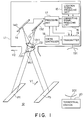
- an image pickup system is for use in a craft 11 flying over an object zone 12 which is typically on the Earth.
- the object zone 12 moves with a zone velocity V1 relative to the center of the Earth.
- the craft 11 is typically a space craft. Alternatively, the craft 11 may be an aircraft. In any event, the craft 11 moves with a craft velocity V2 relative to the center of the Earth. It is therefore possible to say that the object zone 12 moves independently relative to the craft 11.
- the image pickup system comprises in the craft 11 a first camera unit 13, a second camera unit 14, a location signal producing unit 15, a correcting signal producing unit 16, and a processing unit 17, all of which will become clear as the description proceeds.
- a timing controller 18 and a transmitter 19 are installed in the craft 11.
- the image pickup system may be used in combination with a terrestrial station 20. In this event, an equivalent of the location signal producing unit 15 may be installed in the terrestrial station 20.
- the first camera unit 13 produces a forward electric signal representative of a forward partial zone Pf of the object zone 12.
- the second camera unit 14 produces a backward electric signal representative of a backward partial zone Pb of the object zone 12.
- the craft 11 is depicted at first and second locations L1 and L2.
- the forward partial zone Pf is viewed as a first partial zone P1.
- the backward partial zone Pb is viewed as a second partial zone P2.
- the first and the second partial zones P1 and P2 will be discussed more in detail in the following.
- the first camera unit 13 produces the forward electric signal as a first electric signal representative of the first partial zone P1.
- the first camera unit 13 comprises a first lens system 131 for producing a first image of the first partial zone P1 and a first image processor 132 for processing the first image into the first electric signal.
- the first lens system 131 includes a lens 1311 having a first focal length for forming the first image.
- the second camera unit 14 produces the backward electric signal as a second electric signal representative of the second partial zone P2.
- the second camera unit 14 comprises a second lens system 141 for producing a second image of the second partial zone P2 and a second image processor 142 for processing the second image into the second electric signal.
- the second lens system 141 includes a lens 1411 having a second focal length for forming the second image. It is possible to understand without loss of generality that the first and the second focal lengths are equal to each other. The first or the second focal length may therefore be referred to as a common focal length.
- the object zone 12 moves while the craft 11 moves from the first location L1 to the second location L2.
- the first and the second partial zones P1 and P2 are therefore different by a difference zone DZ (Fig. 3).
- the first and the second partial zones P1 and P2 partially overlap on each other to leave a first nonoverlapped zone NZ1 in the first partial zone P1 and a second nonoverlapped zone NZ2 in the second partial zone P2.
- the first and the second nonoverlapped zones NZ1 and NZ2 collectively providing the difference zone DZ described in conjunction with Fig. 3.
- the first nonoverlapped zone NZ1 has a first area.
- the second nonoverlapped zone NZ2 has a second area.
- the difference zone DZ has a collective area. The collective area is equal to a sum of the first area and the second area.
- the craft 11 views the first partial zone P1 in a first direction from the first location L1 and the second partial zone P2 in a second direction from the second location L2. Being considerably remote from the Earth, the craft 11 has a common space distance from each of the first and the second partial zones P1 and P2.
- the location signal producing unit 15 comprises a first location signal producing circuit 151 and a second location signal producing circuit 152.
- the first location signal producing circuit 151 produces the first location signal representative of the first location L1 by using the first direction and the common space distance.
- the second location signal producing circuit 152 produces the second location signal representative of the second location L2 by using the second direction and the common space distance.
- the correcting signal producing unit 16 is connected to the location signal producing unit 15 and produces an overall correcting signal by calculating a distance quotient of the common focal length by the common space distance and a three-term product of the distance quotient, the zone velocity V1, and the predetermined time interval by making the overall correcting signal represent the three-term product. It therefore follows that the overall correcting signal specifies the difference zone DZ (Fig. 3).
- the correcting signal producing unit 16 comprises a first correcting signal producing circuit 161 connected to the first location signal producing circuit 151 and a second correcting signal producing circuit 162 connected to the second location signal producing circuit 152.
- the first correcting signal producing circuit 161 is connected to the first location signal producing circuit 151 and produces the first correcting signal by calculating a distance quotient of the common focal length by the common space distance, a first quotient of the first area by the collective area, and first four-term product of the distance quotient, the zone velocity V1, the predetermined time interval, and the first quotient and by making the first correcting signal represent the first four-term product.
- the first correcting signal specifies the first nonoverlapped zone NZ1 (Fig. 4).
- the second correcting signal producing circuit 162 is connected to the second location signal producing circuit 152 and produces the second correcting signal by calculating the distance quotient, a second quotient of the second area by the collective area, and a second four-term product of the distance quotient, the zone velocity V1, the predetermined time interval, and the second quotient and by making the second correcting signal represent the second four-term product.
- the second correcting signal specifies the second nonoverlapped zone NZ2 (Fig. 4).
- the processing unit 17 is connected to the first and the second cameras 13 and 14 and the correcting signal producing unit 16 and processes by the overall correcting signal the first and the second electric signals into first and second image signals for use in producing a stereo image of the object zone 12.
- the processing unit 17 comprises a first corrector 171 and a second corrector 172.
- the first corrector 171 comprises a first RAM 173 connected to the first image processor 132 and a first processing circuit 174 connected to the first correcting signal producing circuit 161 and the first RAM 173.
- the first processing circuit 174 comprises a first read and write timing controller 1741 connected to the first image processor 132, the first RAM 173, and the timing controller 18 and a first correcting circuit 1742 connected to the first correcting signal producing circuit 161, the first read and write timing controller 1741, and the first RAM 173.
- the first image processor 132 produces a first write timing signal while producing the first electric signal.
- the timing controller 18 produces a read timing signal.
- the first read and write timing controller 1741 is supplied with the first write timing signal and supplies a first write signal to the first RAM 173. Supplied with the first electric signal from the first image processor 132 and with the first write signal, the first RAM 173 memorizes the first electric signal as a first memorized signal.
- the first memorized signal comprises a first partial portion and a first remaining partial portion which indicate the first nonoverlapped zone NZ1 and a remaining zone of the first partial zone PZ1, respectively.
- the first read and write timing controller 1741 is supplied with the read timing signal from the timing controller 18 and delivers a first read command signal to the first correcting circuit 1742.
- the first correcting circuit 1742 Supplied with the first correcting signal from the first correcting signal producing circuit 161 and with the first read command signal, the first correcting circuit 1742 produces a first read control signal which comprises a first inhibit signal and a first read signal.
- the first inhibit signal is produced while the first correcting circuit 1742 is supplied with the first correcting signal.
- the first RAM 173 Supplied with the first inhibit signal, the first RAM 173 is inhibited from producing the first partial portion indicating the first nonoverlapped zone NZ1. Supplied with the first read signal, the first RAM 173 produces the first image signal.
- the second corrector 172 comprises a second RAM 175 connected to the second image processor 142 and a second processing circuit 176 connected to the second correcting signal producing circuit 162 and the second RAM 176.
- the second processing circuit 176 comprises a second read and write timing controller 1761 connected to the second image processor 142, the second RAM 175, and the timing controller 18 and a second correcting circuit 1762 connected to the second correcting signal producing circuit 162, the second read and write timing controller 1761, and the second RAM 175.
- the second image processor 142 produces a second write timing signal while producing the second electric signal.
- the second read and write timing controller 1761 is supplied with the second write timing signal and supplies a second write signal to the second RAM 175. Supplied with the second electric signal from the second image processor 142 and with the second write signal, the second RAM 175 memorizes the second electric signal as a second memorized signal.
- the second memorized signal comprises a second partial portion and a second remaining partial portion which indicate the second nonoverlapped zone NZ2 and a remaining zone of the second partial zone PZ2, respectively.
- the second read and write timing controller 1761 is supplied with the read timing signal from the timing controller 18 and delivers a second read command signal to the second correcting circuit 1762. Supplied with the second correcting signal from the second correcting signal producing circuit 162 and with the second read command signal, the second correcting circuit 1762 produces a second read control signal which comprises a second inhibit signal and a second read signal. The second inhibit signal is produced while the second correcting circuit 1762 is supplied with the second correcting signal. Supplied with the second inhibit signal, the second RAM 175 is inhibited from producing the second partial portion indicating the second nonoverlapped zone NZ2. Supplied with the second read signal, the second RAM 175 produces the second image signal. It is now understood that the timing controller 18 should produce the read timing signal immediately after the first and the second electric signals are entirely memorized in the first and the second RAMs 173 and 175.
- the transmitter 19 is connected to the first RAM 173, the second RAM 175, and the timing controller 18.
- the timing controller 18 produces a transmission timing signal for supply to the transmitter 19 while the first and the second RAMs 173 and 175 produces the first and the second image signals.
- the transmitter 19 transmits the first and the second image signals to the terrestrial station 20 through an antenna 191 (Fig. 1) of the craft 11.
- the terrestrial station 20 Supplied with the first and the second image signals through an antenna 201 (Fig. 1), the terrestrial station 20 produces a stereo image of the object zone 12 by using the first and the second image signals in a usual manner.
- the stereo image may be produced by a stereo image producing unit (not shown) which is installed in the craft 11.
- the location signal producing unit 15 may be installed in the terrestrial station 20.
- the first and the second location signals are supplied to the correcting signal producing unit 16 through the antennas 201 and 191.
Landscapes
- Engineering & Computer Science (AREA)
- Multimedia (AREA)
- Signal Processing (AREA)
- Physics & Mathematics (AREA)
- General Physics & Mathematics (AREA)
- Radar, Positioning & Navigation (AREA)
- Remote Sensing (AREA)
- Studio Devices (AREA)
- Testing, Inspecting, Measuring Of Stereoscopic Televisions And Televisions (AREA)
- Stereoscopic And Panoramic Photography (AREA)
Applications Claiming Priority (2)
| Application Number | Priority Date | Filing Date | Title |
|---|---|---|---|
| US07/755,553 US5138444A (en) | 1991-09-05 | 1991-09-05 | Image pickup system capable of producing correct image signals of an object zone |
| CA002050804A CA2050804C (en) | 1991-09-05 | 1991-09-06 | Image pickup system capable of producing correct image signals of an object zone |
Publications (2)
| Publication Number | Publication Date |
|---|---|
| EP0530391A1 true EP0530391A1 (de) | 1993-03-10 |
| EP0530391B1 EP0530391B1 (de) | 1996-12-11 |
Family
ID=25674780
Family Applications (1)
| Application Number | Title | Priority Date | Filing Date |
|---|---|---|---|
| EP91114763A Expired - Lifetime EP0530391B1 (de) | 1991-09-05 | 1991-09-02 | Bildaufnahmesystem, das korrekte Bildsignale einer Objektzone erzeugen kann |
Country Status (4)
| Country | Link |
|---|---|
| US (1) | US5138444A (de) |
| EP (1) | EP0530391B1 (de) |
| CA (1) | CA2050804C (de) |
| DE (1) | DE69123578T2 (de) |
Cited By (1)
| Publication number | Priority date | Publication date | Assignee | Title |
|---|---|---|---|---|
| WO1999017077A1 (en) * | 1997-09-30 | 1999-04-08 | Lockheed Martin Corporation | Method and apparatus for remote display of photogrammetric imagery |
Families Citing this family (42)
| Publication number | Priority date | Publication date | Assignee | Title |
|---|---|---|---|---|
| JPH05265081A (ja) * | 1992-03-23 | 1993-10-15 | Canon Inc | 複眼撮像装置 |
| DE4216828C2 (de) * | 1992-05-21 | 1994-08-18 | Dornier Gmbh | Verfahren zur Erdbeobachtung |
| JPH06191093A (ja) * | 1992-12-25 | 1994-07-12 | Fuji Xerox Co Ltd | 記録装置 |
| DE4428054C1 (de) * | 1994-07-29 | 1995-08-24 | Innotech Holztechnologien Gmbh | Anordnung und Verfahren zur stereoskopischen optoelektronischen Bildgewinnung |
| US5668593A (en) * | 1995-06-07 | 1997-09-16 | Recon/Optical, Inc. | Method and camera system for step frame reconnaissance with motion compensation |
| US6747686B1 (en) | 2001-10-05 | 2004-06-08 | Recon/Optical, Inc. | High aspect stereoscopic mode camera and method |
| US7893957B2 (en) * | 2002-08-28 | 2011-02-22 | Visual Intelligence, LP | Retinal array compound camera system |
| US8483960B2 (en) * | 2002-09-20 | 2013-07-09 | Visual Intelligence, LP | Self-calibrated, remote imaging and data processing system |
| US7725258B2 (en) * | 2002-09-20 | 2010-05-25 | M7 Visual Intelligence, L.P. | Vehicle based data collection and processing system and imaging sensor system and methods thereof |
| US8994822B2 (en) | 2002-08-28 | 2015-03-31 | Visual Intelligence Lp | Infrastructure mapping system and method |
| USRE49105E1 (en) | 2002-09-20 | 2022-06-14 | Vi Technologies, Llc | Self-calibrated, remote imaging and data processing system |
| US7424133B2 (en) * | 2002-11-08 | 2008-09-09 | Pictometry International Corporation | Method and apparatus for capturing, geolocating and measuring oblique images |
| US7248794B2 (en) * | 2003-06-12 | 2007-07-24 | Imagesat International N.V. | Remote platform multiple capture image formation method and apparatus |
| US7873238B2 (en) | 2006-08-30 | 2011-01-18 | Pictometry International Corporation | Mosaic oblique images and methods of making and using same |
| JP4709101B2 (ja) * | 2006-09-01 | 2011-06-22 | キヤノン株式会社 | 自動追尾カメラ装置 |
| US8593518B2 (en) * | 2007-02-01 | 2013-11-26 | Pictometry International Corp. | Computer system for continuous oblique panning |
| US8520079B2 (en) * | 2007-02-15 | 2013-08-27 | Pictometry International Corp. | Event multiplexer for managing the capture of images |
| US9262818B2 (en) | 2007-05-01 | 2016-02-16 | Pictometry International Corp. | System for detecting image abnormalities |
| US8385672B2 (en) | 2007-05-01 | 2013-02-26 | Pictometry International Corp. | System for detecting image abnormalities |
| US7991226B2 (en) | 2007-10-12 | 2011-08-02 | Pictometry International Corporation | System and process for color-balancing a series of oblique images |
| US8531472B2 (en) | 2007-12-03 | 2013-09-10 | Pictometry International Corp. | Systems and methods for rapid three-dimensional modeling with real façade texture |
| US8675068B2 (en) | 2008-04-11 | 2014-03-18 | Nearmap Australia Pty Ltd | Systems and methods of capturing large area images in detail including cascaded cameras and/or calibration features |
| US8497905B2 (en) | 2008-04-11 | 2013-07-30 | nearmap australia pty ltd. | Systems and methods of capturing large area images in detail including cascaded cameras and/or calibration features |
| US8588547B2 (en) | 2008-08-05 | 2013-11-19 | Pictometry International Corp. | Cut-line steering methods for forming a mosaic image of a geographical area |
| IL198883A (en) * | 2009-05-21 | 2015-03-31 | Israel Aerospace Ind Ltd | Method and system for stereoscopic scanning |
| US8401222B2 (en) | 2009-05-22 | 2013-03-19 | Pictometry International Corp. | System and process for roof measurement using aerial imagery |
| US9330494B2 (en) | 2009-10-26 | 2016-05-03 | Pictometry International Corp. | Method for the automatic material classification and texture simulation for 3D models |
| US8477190B2 (en) | 2010-07-07 | 2013-07-02 | Pictometry International Corp. | Real-time moving platform management system |
| US8823732B2 (en) | 2010-12-17 | 2014-09-02 | Pictometry International Corp. | Systems and methods for processing images with edge detection and snap-to feature |
| US10325350B2 (en) | 2011-06-10 | 2019-06-18 | Pictometry International Corp. | System and method for forming a video stream containing GIS data in real-time |
| US9183538B2 (en) | 2012-03-19 | 2015-11-10 | Pictometry International Corp. | Method and system for quick square roof reporting |
| US9244272B2 (en) | 2013-03-12 | 2016-01-26 | Pictometry International Corp. | Lidar system producing multiple scan paths and method of making and using same |
| US9881163B2 (en) | 2013-03-12 | 2018-01-30 | Pictometry International Corp. | System and method for performing sensitive geo-spatial processing in non-sensitive operator environments |
| US9753950B2 (en) | 2013-03-15 | 2017-09-05 | Pictometry International Corp. | Virtual property reporting for automatic structure detection |
| US9275080B2 (en) | 2013-03-15 | 2016-03-01 | Pictometry International Corp. | System and method for early access to captured images |
| ES2684643T3 (es) | 2014-01-10 | 2018-10-03 | Pictometry International Corp. | Sistema y procedimiento de evaluación de estructura mediante aeronave no tripulada |
| US9292913B2 (en) | 2014-01-31 | 2016-03-22 | Pictometry International Corp. | Augmented three dimensional point collection of vertical structures |
| WO2015120188A1 (en) | 2014-02-08 | 2015-08-13 | Pictometry International Corp. | Method and system for displaying room interiors on a floor plan |
| CA3001023A1 (en) | 2016-01-08 | 2017-07-13 | Pictometry International Corp. | Systems and methods for taking, processing, retrieving, and displaying images from unmanned aerial vehicles |
| EP3403050A4 (de) | 2016-02-15 | 2019-08-21 | Pictometry International Corp. | Automatisiertes system und verfahren zur merkmalsextraktion |
| US10671648B2 (en) | 2016-02-22 | 2020-06-02 | Eagle View Technologies, Inc. | Integrated centralized property database systems and methods |
| US12332660B2 (en) | 2018-11-21 | 2025-06-17 | Eagle View Technologies, Inc. | Navigating unmanned aircraft using pitch |
Citations (3)
| Publication number | Priority date | Publication date | Assignee | Title |
|---|---|---|---|---|
| US2931857A (en) * | 1955-09-23 | 1960-04-05 | Hammond Jr | Television reconnaissance system |
| EP0135345A1 (de) * | 1983-08-12 | 1985-03-27 | Nec Corporation | Bildaufnahmesystem zur Wiedergabe eines Stereo- u./o. Nichtstereobildes unter Verwendung eines einzigen optischen Systems |
| EP0361297A1 (de) * | 1988-09-20 | 1990-04-04 | Nec Corporation | Bildaufnahmesystem zur Erzeugung einer Vielzahl von Stereobildern mit verschiedenen Basis/Höhen-Verhältnissen |
Family Cites Families (2)
| Publication number | Priority date | Publication date | Assignee | Title |
|---|---|---|---|---|
| DE2940871C2 (de) * | 1979-10-09 | 1983-11-10 | Messerschmitt-Bölkow-Blohm GmbH, 8012 Ottobrunn | Photogrammetrisches Verfahren für Fluggeräte und Raumflugkörper zur digitalen Geländedarstellung |
| DE3802219A1 (de) * | 1988-01-26 | 1989-08-03 | Deutsche Forsch Luft Raumfahrt | Verfahren und einrichtung zur fernerkundung der erde |
-
1991
- 1991-09-02 DE DE69123578T patent/DE69123578T2/de not_active Expired - Lifetime
- 1991-09-02 EP EP91114763A patent/EP0530391B1/de not_active Expired - Lifetime
- 1991-09-05 US US07/755,553 patent/US5138444A/en not_active Expired - Lifetime
- 1991-09-06 CA CA002050804A patent/CA2050804C/en not_active Expired - Lifetime
Patent Citations (3)
| Publication number | Priority date | Publication date | Assignee | Title |
|---|---|---|---|---|
| US2931857A (en) * | 1955-09-23 | 1960-04-05 | Hammond Jr | Television reconnaissance system |
| EP0135345A1 (de) * | 1983-08-12 | 1985-03-27 | Nec Corporation | Bildaufnahmesystem zur Wiedergabe eines Stereo- u./o. Nichtstereobildes unter Verwendung eines einzigen optischen Systems |
| EP0361297A1 (de) * | 1988-09-20 | 1990-04-04 | Nec Corporation | Bildaufnahmesystem zur Erzeugung einer Vielzahl von Stereobildern mit verschiedenen Basis/Höhen-Verhältnissen |
Non-Patent Citations (1)
| Title |
|---|
| PATENT ABSTRACTS OF JAPAN vol. 8, no. 74 (E-236)(1511) 6 April 1984 & JP-A-58 220 571 ( MITSUBISHI DENKI K.K. ) 22 December 1983 * |
Cited By (1)
| Publication number | Priority date | Publication date | Assignee | Title |
|---|---|---|---|---|
| WO1999017077A1 (en) * | 1997-09-30 | 1999-04-08 | Lockheed Martin Corporation | Method and apparatus for remote display of photogrammetric imagery |
Also Published As
| Publication number | Publication date |
|---|---|
| US5138444A (en) | 1992-08-11 |
| DE69123578T2 (de) | 1997-04-03 |
| CA2050804C (en) | 1996-07-02 |
| CA2050804A1 (en) | 1993-03-07 |
| DE69123578D1 (de) | 1997-01-23 |
| EP0530391B1 (de) | 1996-12-11 |
Similar Documents
| Publication | Publication Date | Title |
|---|---|---|
| US5138444A (en) | Image pickup system capable of producing correct image signals of an object zone | |
| US4807024A (en) | Three-dimensional display methods and apparatus | |
| US6144761A (en) | Photogrammetric analytical measurement system | |
| US4805015A (en) | Airborne stereoscopic imaging system | |
| US5155683A (en) | Vehicle remote guidance with path control | |
| EP0757798B1 (de) | Kamerafuhrungssystem | |
| EP0294101B1 (de) | Anordnung zum Messen einer Winkelverschiebung eines Gegenstandes | |
| US5259037A (en) | Automated video imagery database generation using photogrammetry | |
| US8274550B2 (en) | Digital 3D/360 degree camera system | |
| JP2807622B2 (ja) | 航空機搭載総合撮影装置 | |
| EP1087257B1 (de) | Stereoskopisches Kamerasystem in einem Fahrzeug | |
| WO2009087543A2 (en) | System and method for navigating a remote control vehicle past obstacles | |
| WO2003032649A1 (en) | High aspect stereoscopic mode camera and method | |
| US5995765A (en) | Camera with distance-measuring sensor unit for use in photogrammetric analytical measurement | |
| GB2149258A (en) | Image correction system | |
| US12210358B2 (en) | Autonomous orbiting method and device and uav | |
| TW593978B (en) | Video picture processing method | |
| EP0361297A1 (de) | Bildaufnahmesystem zur Erzeugung einer Vielzahl von Stereobildern mit verschiedenen Basis/Höhen-Verhältnissen | |
| US4504914A (en) | Photogrammetric device for aircraft and spacecraft for producing a digital terrain representation | |
| JP2000085694A (ja) | 着陸支援センサ装置及び、これを用いた垂直離着陸機の着陸支援システム | |
| JP2695393B2 (ja) | 位置特定方法および装置 | |
| JP2003219252A (ja) | 移動体搭載用撮影装置を用いた撮影システム及び撮影方法 | |
| CN114877872A (zh) | 无人机及其操作系统、生成测绘图的方法、介质、设备 | |
| JPH09231370A (ja) | 画像情報入力装置 | |
| JP2560398B2 (ja) | 航空測量装置 |
Legal Events
| Date | Code | Title | Description |
|---|---|---|---|
| PUAI | Public reference made under article 153(3) epc to a published international application that has entered the european phase |
Free format text: ORIGINAL CODE: 0009012 |
|
| 17P | Request for examination filed |
Effective date: 19910925 |
|
| AK | Designated contracting states |
Kind code of ref document: A1 Designated state(s): DE FR GB |
|
| 17Q | First examination report despatched |
Effective date: 19940428 |
|
| GRAH | Despatch of communication of intention to grant a patent |
Free format text: ORIGINAL CODE: EPIDOS IGRA |
|
| GRAH | Despatch of communication of intention to grant a patent |
Free format text: ORIGINAL CODE: EPIDOS IGRA |
|
| GRAA | (expected) grant |
Free format text: ORIGINAL CODE: 0009210 |
|
| AK | Designated contracting states |
Kind code of ref document: B1 Designated state(s): DE FR GB |
|
| REF | Corresponds to: |
Ref document number: 69123578 Country of ref document: DE Date of ref document: 19970123 |
|
| ET | Fr: translation filed | ||
| PLBE | No opposition filed within time limit |
Free format text: ORIGINAL CODE: 0009261 |
|
| STAA | Information on the status of an ep patent application or granted ep patent |
Free format text: STATUS: NO OPPOSITION FILED WITHIN TIME LIMIT |
|
| 26N | No opposition filed | ||
| REG | Reference to a national code |
Ref country code: GB Ref legal event code: IF02 |
|
| REG | Reference to a national code |
Ref country code: GB Ref legal event code: 732E |
|
| REG | Reference to a national code |
Ref country code: FR Ref legal event code: TP |
|
| PGFP | Annual fee paid to national office [announced via postgrant information from national office to epo] |
Ref country code: FR Payment date: 20100921 Year of fee payment: 20 |
|
| PGFP | Annual fee paid to national office [announced via postgrant information from national office to epo] |
Ref country code: GB Payment date: 20100901 Year of fee payment: 20 |
|
| PGFP | Annual fee paid to national office [announced via postgrant information from national office to epo] |
Ref country code: DE Payment date: 20100825 Year of fee payment: 20 |
|
| REG | Reference to a national code |
Ref country code: DE Ref legal event code: R071 Ref document number: 69123578 Country of ref document: DE |
|
| REG | Reference to a national code |
Ref country code: DE Ref legal event code: R071 Ref document number: 69123578 Country of ref document: DE |
|
| REG | Reference to a national code |
Ref country code: GB Ref legal event code: PE20 Expiry date: 20110901 |
|
| PG25 | Lapsed in a contracting state [announced via postgrant information from national office to epo] |
Ref country code: GB Free format text: LAPSE BECAUSE OF EXPIRATION OF PROTECTION Effective date: 20110901 |
|
| PG25 | Lapsed in a contracting state [announced via postgrant information from national office to epo] |
Ref country code: DE Free format text: LAPSE BECAUSE OF EXPIRATION OF PROTECTION Effective date: 20110903 |