EP0530471B1 - Dispositif de commande pour une soupape de mélange - Google Patents
Dispositif de commande pour une soupape de mélange Download PDFInfo
- Publication number
- EP0530471B1 EP0530471B1 EP92111933A EP92111933A EP0530471B1 EP 0530471 B1 EP0530471 B1 EP 0530471B1 EP 92111933 A EP92111933 A EP 92111933A EP 92111933 A EP92111933 A EP 92111933A EP 0530471 B1 EP0530471 B1 EP 0530471B1
- Authority
- EP
- European Patent Office
- Prior art keywords
- cap
- stop
- axially
- desired value
- setting device
- Prior art date
- Legal status (The legal status is an assumption and is not a legal conclusion. Google has not performed a legal analysis and makes no representation as to the accuracy of the status listed.)
- Expired - Lifetime
Links
- 210000002105 tongue Anatomy 0.000 claims description 13
- XLYOFNOQVPJJNP-UHFFFAOYSA-N water Substances O XLYOFNOQVPJJNP-UHFFFAOYSA-N 0.000 claims description 4
- 229920003023 plastic Polymers 0.000 claims description 2
- 239000004033 plastic Substances 0.000 claims description 2
- 239000000463 material Substances 0.000 claims 1
- 230000001105 regulatory effect Effects 0.000 abstract 2
- 230000015572 biosynthetic process Effects 0.000 abstract 1
- 238000005755 formation reaction Methods 0.000 abstract 1
- 210000003128 head Anatomy 0.000 description 10
- 210000001331 nose Anatomy 0.000 description 6
- 230000000694 effects Effects 0.000 description 1
- 230000000630 rising effect Effects 0.000 description 1
Images


Classifications
-
- F—MECHANICAL ENGINEERING; LIGHTING; HEATING; WEAPONS; BLASTING
- F16—ENGINEERING ELEMENTS AND UNITS; GENERAL MEASURES FOR PRODUCING AND MAINTAINING EFFECTIVE FUNCTIONING OF MACHINES OR INSTALLATIONS; THERMAL INSULATION IN GENERAL
- F16K—VALVES; TAPS; COCKS; ACTUATING-FLOATS; DEVICES FOR VENTING OR AERATING
- F16K35/00—Means to prevent accidental or unauthorised actuation
- F16K35/02—Means to prevent accidental or unauthorised actuation to be locked or disconnected by means of a pushing or pulling action
- F16K35/022—Means to prevent accidental or unauthorised actuation to be locked or disconnected by means of a pushing or pulling action the locking mechanism being actuated by a separate actuating element
- F16K35/025—Means to prevent accidental or unauthorised actuation to be locked or disconnected by means of a pushing or pulling action the locking mechanism being actuated by a separate actuating element said actuating element being operated manually (e.g. a push-button located in the valve actuator)
-
- G—PHYSICS
- G05—CONTROLLING; REGULATING
- G05D—SYSTEMS FOR CONTROLLING OR REGULATING NON-ELECTRIC VARIABLES
- G05D23/00—Control of temperature
- G05D23/01—Control of temperature without auxiliary power
- G05D23/13—Control of temperature without auxiliary power by varying the mixing ratio of two fluids having different temperatures
- G05D23/1306—Control of temperature without auxiliary power by varying the mixing ratio of two fluids having different temperatures for liquids
- G05D23/132—Control of temperature without auxiliary power by varying the mixing ratio of two fluids having different temperatures for liquids with temperature sensing element
- G05D23/134—Control of temperature without auxiliary power by varying the mixing ratio of two fluids having different temperatures for liquids with temperature sensing element measuring the temperature of mixed fluid
- G05D23/1346—Control of temperature without auxiliary power by varying the mixing ratio of two fluids having different temperatures for liquids with temperature sensing element measuring the temperature of mixed fluid with manual temperature setting means
Definitions
- the invention relates to a setpoint adjustment device on a thermostatically controlled mixing valve for cold and hot water, with an adjusting nut that can be screwed onto a fixed head piece, on which a hood is held in a rotationally fixed manner, with a fixed stop ring that limits the maximum rotary movement, and a scale arrangement cooperates, wherein a manually releasable stop is provided as an additional rotation limit.
- Such a device is known from the document DE 35 30 812 A1.
- the temperature of the adjusting handle is shifted axially to the mixing valve in accordance with the thread pitch on the head piece, which is often regarded as disadvantageous.
- this configuration does not provide for an optional setting of the safety stop which can be released by hand to different temperature values.
- An adjustable safety stop device has already become known for another setpoint adjustment device (German specification 1 161 460).
- the invention has for its object to improve the adjusting device specified in the preamble of claim 1, it being part of the task to make the safety stop or the releasable stop adjustable.
- the temperature scale handle consisting of a hood and a handle cap, maintains the same position axially to the head piece in the temperature setting, which is carried out with a rotary movement of the handle, or the scale handle is not arranged rising to the mixing valve, so that a defined, constant gap between the temperature scale handle and the valve body is made possible.
- the subdivision of the handle into a hood and a handle cap makes it easy and convenient to set the safety stop in one Range from 30 ° C to 50 ° C possible.
- the grip cap can be designed such that it can be plugged onto the hood in various rotational angle positions.
- the handle cap can also be axially displaceably arranged on the hood, in which case the handle cap is non-rotatably connected to the hood in a first latched axial position, while in the other axial position it is rotatably supported on the hood, so that the handle cap is lost is excluded.
- the parts of the temperature scale handle, in particular the hood, can expediently be produced from plastic.
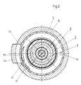
- the setpoint adjustment device shown in Figures 1 to 3 is arranged on a head piece 1 of a thermostatically controlled mixing valve for cold and hot water, not shown in the drawing, as is known for example from the document DE 35 30 812 A1.
- a head piece 1 of a thermostatically controlled mixing valve for cold and hot water not shown in the drawing, as is known for example from the document DE 35 30 812 A1.
- an adjusting nut 2 with a thread 21 is axially movable.
- the adjusting nut 2 acts via an overload safety device 11 on a valve rod 12 which is connected to a thermostatic element (not shown in the drawing) and the mixing valve member.
- a serration 22 is arranged, which is rotatably but axially slidably engaged with a hood 4.
- a stop ring 3 is also held in a rotationally fixed manner by means of a serration 13.
- the stop ring 3 is provided with locking tongues 33 which engage in a circumferential annular groove 14 on the head piece 1 in the plug-in position.
- the adjusting nut 2 engages with an elastic brake ring 23 in a cylindrical bore 34, so that a certain stiffness of the adjusting nut 2 is generated by the frictional action of the brake ring 23 on the wall of the bore 34, so that a self-adjusting effect is eliminated.
- the locking tongues 33 are locked in the inserted position by the slid-on hood 4.
- the hood 4 To axially secure the hood 4, it engages with locking tongues 42 in a circumferential annular groove 35 on the stop ring 3. With this arrangement, the hood 4 is axially fixed but rotatable on the head piece 1 held, wherein it is connected in a rotationally fixed manner to the adjusting nut 2 which can be displaced axially via the thread 21.
- a stop lug 31 is formed on the stop ring 3, as can be seen in particular from FIG. 3, which limits the maximum angle of rotation both in cooperation with a stop 46 and also the counterpart for a ring segment 52, described in more detail below and designed on a safety button 54 for a detachable stop 51 forms.
- the hood 4 is designed as a three-stage sleeve, with a scale 43 for the temperature display on the area with the largest diameter, the locking tongues 42 on the middle level and a serration 44 on the smallest diameter on the outer circumference, on which a grip cap 5 with corresponding serration 44 can be pushed on.
- the latching tongues 42 are locked in the latched position by the grip cap 5, so that pulling off the hood 4 from the head piece 1 is excluded.
- the safety button 54 is arranged, which can be moved radially inward against the force of a spring 55 by the user.
- the ring segment 52 is formed with a stop 51 which, in the assembled state, cooperates with the stop nose 31 of the stop ring 3.
- the ring segment 52 is axially passed through a slot 41 arranged in a ring in the end wall of the hood 4.
- an inclined side surface 53 is formed on the ring segment 52, as can be seen in particular from FIG. 2. This beveled side surface 53 makes it possible for the ring segment 52 of the ring segment 52 to be reset or turned back Safety button 54 can slide past the stop nose 31 automatically and the stop is only effective in one direction of rotation.
- the handle cap 5 is fixed in the position shown in Figure 1 by snap tongues 45 in the plug-in position, so that with a rotary movement this is transferred to the hood 4 and from here to the adjusting nut 2, which by means of the thread 21 corresponding to the rotary movement in the axially fixed handle arrangement, consisting of hood 4 and handle cap 5, is correspondingly axially displaced and transmits the axial actuating movement to the valve rod 12 via a pressure pin.
- the stop ring 3 essentially overlaps the hood 4 with the largest diameter step on which the scale 43 is arranged.
- an aperture ring 32 is fixed on the stop ring 3 in a rotationally fixed manner and overlaps the scale 43 with play.
- an opening 321 is formed in the aperture ring 32, through which the respectively set temperature can be read on the setpoint adjustment device.
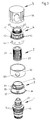
- the setpoint adjustment device can be assembled in the order of the individual parts shown in FIG.
- the stop ring 3 is first attached to the head piece 1, which protrudes from the housing of the mixing valve, not shown in the drawing, and locked with the locking tongues 33.
- the aperture ring 32 can be placed on the stop ring 3 and connected to the stop ring 3 in a rotationally fixed manner by means of a radial projection 36.
- the adjusting nut 2 with the brake ring 23 can be screwed onto the thread 21, so that the brake ring 23 is frictionally received by the wall of the bore 34 and prevents an automatic adjustment.
- the hood 4 can then be pushed onto the adjusting nut 2 and connected axially fixed to the stop ring 3 with the aid of the locking tongues 42. Finally, the handle cap 5 is pushed onto the hood 4 with the safety button 54 and locked in the plug-in position by the snap tongues 45.
- the respectively set mixed water temperature can thus be read by rotating the grip cap 5 at the opening 321 of the diaphragm ring 32.
- the position and size of the slot 41 in the hood 4 determines both the size and the location of the predetermined setting range, for example 30 ° C to 50 ° C, of the releasable stop 51, since the ring segment 52 extends through the slot 41 to with the Stop lug 31 to correspond.
- the detachable stop 51 can be set to a desired temperature, for example 45 ° C.
- a desired temperature for example 45 ° C.
- the desired temperature is set with the handle cap 5 on the aperture ring 32 and then the handle cap 5 is pulled off the hood 4 and rotated again so that the stop 51 bears against the stop lug 31.
- the handle cap 5 can only be turned up to the set temperature, for example 45 ° C.
- the safety button 54 must be used to move the stop 51 radially inwards to such an extent that it can be moved past the stop nose 31.
- the ring segment 52 with the stop 51 is automatically deflected inwards by the slanted side surface 53 and the return to the lower temperature range is made possible.
- the stop 51 comes to rest against the stop nose 31 at the predetermined temperature.
- the handle cap 5 is captively attached to the hood 4.
- the snap tongues 45 are designed twice, so that the grip cap 5 can be fixed in two axial positions on the hood 4.
- the grip cap 5 has a stop shoulder 56, against which a snap nose 451 provided with an edge at right angles to the central axis comes to rest and prevent the grip cap 5 from being pulled off completely.
- the snap noses 451 are arranged so that when the abutment shoulder 56 is in contact, the grip cap 5 is disengaged from the serration 44 and the grip cap 5 can thus be rotated to the hood 4 in this position.
- a new determination of the desired releasable temperature limit is thus possible without completely removing the handle cap 5 from the hood 4. So that disassembly of the actuating device is possible, an opening which can be closed with a cover 57 is provided on the end face of the grip cap 5. Otherwise, the exemplary embodiment corresponds to that shown in FIGS. 1 to 3.
Landscapes
- Engineering & Computer Science (AREA)
- General Engineering & Computer Science (AREA)
- Mechanical Engineering (AREA)
- Physics & Mathematics (AREA)
- General Physics & Mathematics (AREA)
- Automation & Control Theory (AREA)
- Multiple-Way Valves (AREA)
- Preventing Unauthorised Actuation Of Valves (AREA)
- Temperature-Responsive Valves (AREA)
- Indication Of The Valve Opening Or Closing Status (AREA)
- Processing And Handling Of Plastics And Other Materials For Molding In General (AREA)
- Mechanically-Actuated Valves (AREA)
Claims (9)
- Dispositif de réglage d'une valeur de consigne d'une soupape de mitigeur thermostatique pour de l'eau froide et de l'eau chaude, comportant un écrou de réglage (2) vissé par un filetage (21) sur une tête (1) fixe, filetage qui porte solidairement en rotation une coiffe (4) coopérant avec une bague de butée (3) fixe limitant le mouvement de rotation maximum et une graduation, une butée (51) desserrable à la main servant de moyen supplémentaire pour limiter la température et la rotation, caractérisé en ce que :- la coiffe (4) est maintenue axialement contre la bague de butée (3) et comporte une fente annulaire (41) dans une zone partielle d'une face frontale, formée par une réduction de diamètre,- un capuchon formant poignée (5) peut se fixer dans différentes positions de rotation sur la coiffe (4),- le capuchon formant poignée (5) comporte une butée (51) qui peut être sortie manuellement, par un mouvement radial, à partir de sa position de butée contre un bec de butée (31), et cette butée vient en saillie à travers la fente (41) dans la coiffe (4) et coopère avec un bec de butée (31) formé sur la bague de butée (3), la dimension et la position de la plage de réglage de la butée amovible (51) étant prédéterminées essentiellement par la dimension et la position de la fente (41).
- Dispositif de réglage d'une valeur de consigne selon la revendication 1, caractérisé en ce que la coiffe (4) est maintenue sur la bague de butée (3) par des languettes d'encliquetage (42), fixes, et qui sont verrouillées en position engagée par l'emmanchement du capuchon formant poignée (5).
- Dispositif de réglage d'une valeur de consigne selon la revendication 1 ou 2, caractérisé en ce que la coiffe (4) est une douille à trois gradins, le gradin de plus grand diamètre portant à sa périphérie une échelle (43) pour l'affichage de la température, le gradin moyen comportant une ou plusieurs languettes d'encliquetage (42) et le gradin de plus petit diamètre comportant à sa périphérie extérieure une denture molletée (44) pour recevoir solidairement en rotation, le capuchon formant poignée (5).
- Dispositif de réglage d'une valeur de consigne selon l'une des revendications 1 à 3, caractérisé en ce que le capuchon formant poignée (5) est maintenu en position emmanchée sur la coiffe (4) par des languettes d'encliquetage (45).
- Dispositif de réglage d'une valeur de consigne selon l'une des revendications 1 à 4, caractérisé en ce que le capuchon formant poignée (5) est fixé axialement contre toute extraction accidentelle sur la coiffe (4) et dans une première position axiale, on a une liaison solidaire en rotation par rapport à la coiffe (4) et dans une seconde position axiale, on a une autre position solidaire en rotation.
- Dispositif de réglage d'une valeur de consigne selon l'une des revendications 1 à 5, caractérisé en ce que la butée amovible (51) est réalisée sur un segment annulaire (52) pénétrant dans la fente (41), et dont le côté opposé à la butée (51) comporte une surface latérale (53) inclinée de façon que pour la rotation en sens inverse, le segment annulaire (52) soit déplacé radialement, automatiquement par la surface latérale inclinée (52) et puisse passer sur le bec de butée (31).
- Dispositif de réglage d'une valeur de consigne selon la revendication 6, caractérisé en ce que le segment annulaire (52) est réalisé sur un bouton de sécurité (54) qui peut être coulissé radialement, de manière limitée, contre la force développée par un ressort (55), dans le capuchon formant poignée (5).
- Dispositif de réglage selon l'une des revendications 1 à 7, caractérisé en ce qu'une bague formant cache (32) est montée solidairement en rotation sur la bague de butée (3), cette bague (32) coopérant avec la graduation (43) étant munie d'une ouverture (321) pour afficher la température réglée.
- Dispositif de réglage selon l'une des revendications 1 à 7, caractérisé en ce qu'au moins la coiffe (4) est en matière plastique.
Applications Claiming Priority (2)
| Application Number | Priority Date | Filing Date | Title |
|---|---|---|---|
| DE4123856A DE4123856A1 (de) | 1991-07-18 | 1991-07-18 | Stellvorrichtung fuer ein mischventil |
| DE4123856 | 1991-07-18 |
Publications (2)
| Publication Number | Publication Date |
|---|---|
| EP0530471A1 EP0530471A1 (fr) | 1993-03-10 |
| EP0530471B1 true EP0530471B1 (fr) | 1995-03-08 |
Family
ID=6436479
Family Applications (1)
| Application Number | Title | Priority Date | Filing Date |
|---|---|---|---|
| EP92111933A Expired - Lifetime EP0530471B1 (fr) | 1991-07-18 | 1992-07-14 | Dispositif de commande pour une soupape de mélange |
Country Status (7)
| Country | Link |
|---|---|
| US (1) | US5230465A (fr) |
| EP (1) | EP0530471B1 (fr) |
| JP (1) | JPH05196156A (fr) |
| AT (1) | ATE119696T1 (fr) |
| DE (2) | DE4123856A1 (fr) |
| DK (1) | DK0530471T3 (fr) |
| ES (2) | ES1022845Y (fr) |
Families Citing this family (17)
| Publication number | Priority date | Publication date | Assignee | Title |
|---|---|---|---|---|
| DE9300841U1 (de) * | 1993-01-22 | 1993-03-11 | Hans Grohe Gmbh & Co Kg, 7622 Schiltach | Sanitärarmatur |
| DE19502147C2 (de) * | 1995-01-25 | 1997-11-27 | Ideal Standard | Sanitäre Mischbatterie mit Thermostateinrichtung |
| DE19852618A1 (de) * | 1998-11-14 | 2000-05-18 | Grohe Kg Hans | Drehgriff für ein Sanitärventil |
| DE19926867A1 (de) | 1999-06-12 | 2000-12-14 | Grohe Armaturen Friedrich | Stellvorrichtung |
| KR20020057298A (ko) * | 2001-01-02 | 2002-07-11 | 이근기 | 자폐식 냉,온수 수도전 및 이를 이용한 욕조수위조절장치 |
| DE10153988B4 (de) * | 2001-11-06 | 2011-07-21 | Grohe AG, 58675 | Sollwerteinstellvorrichtung an einem thermostatisch geregelten Mischventil |
| US6676024B1 (en) | 2002-09-05 | 2004-01-13 | Masco Corporation | Thermostatic valve with electronic control |
| ITPD20020236A1 (it) * | 2002-09-16 | 2004-03-17 | Sit La Precisa Spa | Dispositivo di regolazione a manopola, particolarmente |
| US7151240B2 (en) * | 2004-11-22 | 2006-12-19 | Robertshaw Controls Company | Bi-directional tamper resistant temperature dial |
| US7441713B2 (en) * | 2004-11-22 | 2008-10-28 | Robertshaw Controls Company | Tamper resistant temperature dial and associated method of use |
| US7145107B2 (en) * | 2005-03-30 | 2006-12-05 | Robertshaw Controls Company | Tamper resistant temperature dial utilizing deflection pins |
| CN101660621B (zh) * | 2005-05-09 | 2011-09-14 | 科勒公司 | 混合阀 |
| JP5004567B2 (ja) * | 2006-11-30 | 2012-08-22 | 株式会社Lixil | 回転ハンドル装置 |
| DE102013003743A1 (de) * | 2013-03-06 | 2014-09-11 | Grohe Ag | Überlasteinheit für ein Thermostatventil |
| US9638439B2 (en) * | 2015-01-14 | 2017-05-02 | Haier Us Appliance Solutions, Inc. | Water heater appliance |
| DE102016007792A1 (de) * | 2016-06-28 | 2017-12-28 | Grohe Ag | Drehgriff für ein thermostatisch geregeltes Ventil einer Sanitärarmatur mit einem einstellbaren Zwischenanschlag |
| DE102019128364A1 (de) * | 2019-10-21 | 2021-04-22 | Horcher Gmbh | Ventilanordnung |
Family Cites Families (11)
| Publication number | Priority date | Publication date | Assignee | Title |
|---|---|---|---|---|
| DE1161460B (fr) * | 1964-01-16 | |||
| FR1310027A (fr) * | 1963-03-04 | |||
| SE422491B (sv) * | 1978-03-03 | 1982-03-08 | Vaergaarda Armaturfab Ab | Termostatstyrd blandare for tva vetskor |
| DE2921522C2 (de) * | 1979-05-28 | 1981-02-12 | Danfoss A/S, Nordborg (Daenemark) | Drehgriff für Heizkörper-Thermostatventile |
| DE3236372C2 (de) * | 1982-10-01 | 1987-04-30 | Danfoss A/S, Nordborg | Thermostataufsatz für ein Ventil |
| DE3236371C2 (de) * | 1982-10-01 | 1984-08-30 | Danfoss A/S, Nordborg | Thermostatventil |
| US4558819A (en) * | 1984-02-09 | 1985-12-17 | Mcdonald Robert | Automatic valve closer to prevent tampering with a thermostatic controlled radiator |
| GB2172382B (en) * | 1985-03-12 | 1988-09-14 | Caradon Mira Ltd | Fluid mixing valve |
| DE3530812A1 (de) * | 1985-08-29 | 1987-03-05 | Grohe Armaturen Friedrich | Stellvorrichtung fuer ein thermostatisch geregeltes mischventil |
| DE4019233A1 (de) * | 1990-06-15 | 1991-12-19 | Grohe Armaturen Friedrich | Sollwerteinstellvorrichtung fuer ein thermostatisch geregeltes mischventil |
| DE4038141C1 (fr) * | 1990-11-30 | 1992-05-27 | Danfoss A/S, Nordborg, Dk |
-
1991
- 1991-07-18 DE DE4123856A patent/DE4123856A1/de not_active Withdrawn
-
1992
- 1992-07-08 ES ES9202150U patent/ES1022845Y/es not_active Expired - Fee Related
- 1992-07-14 ES ES92111933T patent/ES2072663T3/es not_active Expired - Lifetime
- 1992-07-14 DE DE59201592T patent/DE59201592D1/de not_active Expired - Fee Related
- 1992-07-14 EP EP92111933A patent/EP0530471B1/fr not_active Expired - Lifetime
- 1992-07-14 AT AT92111933T patent/ATE119696T1/de not_active IP Right Cessation
- 1992-07-14 DK DK92111933.5T patent/DK0530471T3/da active
- 1992-07-15 JP JP4187875A patent/JPH05196156A/ja active Pending
- 1992-07-15 US US07/914,760 patent/US5230465A/en not_active Expired - Fee Related
Also Published As
| Publication number | Publication date |
|---|---|
| JPH05196156A (ja) | 1993-08-06 |
| ES1022845Y (es) | 1993-12-16 |
| ATE119696T1 (de) | 1995-03-15 |
| US5230465A (en) | 1993-07-27 |
| EP0530471A1 (fr) | 1993-03-10 |
| DE59201592D1 (de) | 1995-04-13 |
| ES1022845U (es) | 1993-06-01 |
| DE4123856A1 (de) | 1993-01-21 |
| ES2072663T3 (es) | 1995-07-16 |
| DK0530471T3 (da) | 1995-07-31 |
Similar Documents
| Publication | Publication Date | Title |
|---|---|---|
| EP0530471B1 (fr) | Dispositif de commande pour une soupape de mélange | |
| EP0461536B1 (fr) | Dispositif de réglage de la valeur de consigne pour une vanne mélangeuse régulée thermostatiquement | |
| EP1061300B1 (fr) | Actionneur | |
| DE3530812A1 (de) | Stellvorrichtung fuer ein thermostatisch geregeltes mischventil | |
| EP0778434A1 (fr) | Poignée | |
| EP0621427B1 (fr) | Vanne de réglage de débit | |
| EP0733839B1 (fr) | Mitigeur avec un levier | |
| EP0745798A2 (fr) | Poignée pour robinet sanitaire | |
| EP0000878B1 (fr) | Soupape de réglage, spéciallement soupape réglée thermostatiquement | |
| EP1903268A2 (fr) | Poignée de réglage pour un robinet à eau | |
| EP0683341B1 (fr) | Armature sanitaire | |
| WO2002027224A1 (fr) | Mitigeur pour installations sanitaires | |
| EP0552453B1 (fr) | Dispositif de commande pour une soupape de mélange | |
| DE60119061T2 (de) | Justierbare Begrenzungsvorrichtung | |
| DE202025100452U1 (de) | Steuerknopf zur manuellen Feineinstellung von Einrichtung sowie Werkzeug für die Montage eines solchen Steuerknopfs | |
| EP0552452B1 (fr) | Dispositif de commande pour une soupape de mélange | |
| DE4442402C2 (de) | Thermostatkopf für Heizungsventile | |
| EP0496103B1 (fr) | Soupape sanitaire avec sortie orientable | |
| EP0264585B1 (fr) | Elément d'impression | |
| DE3040627A1 (de) | Drehgriff fuer heizkoerper-thermostatventile | |
| EP1621951B1 (fr) | Mitigeur avec dispositif d'actionnement | |
| DE2158950A1 (de) | Thermostatisches radiatorventil | |
| EP3540129A1 (fr) | Robinetterie sanitaire | |
| DE2824529A1 (de) | Ventil mit einem bedienungselement fuer die steuerung zweier funktionen | |
| DE3830312C2 (fr) |
Legal Events
| Date | Code | Title | Description |
|---|---|---|---|
| PUAI | Public reference made under article 153(3) epc to a published international application that has entered the european phase |
Free format text: ORIGINAL CODE: 0009012 |
|
| AK | Designated contracting states |
Kind code of ref document: A1 Designated state(s): AT CH DE DK ES FR GB IT LI NL SE |
|
| 17P | Request for examination filed |
Effective date: 19930522 |
|
| 17Q | First examination report despatched |
Effective date: 19930713 |
|
| GRAA | (expected) grant |
Free format text: ORIGINAL CODE: 0009210 |
|
| AK | Designated contracting states |
Kind code of ref document: B1 Designated state(s): AT CH DE DK ES FR GB IT LI NL SE |
|
| PG25 | Lapsed in a contracting state [announced via postgrant information from national office to epo] |
Ref country code: NL Free format text: LAPSE BECAUSE OF FAILURE TO SUBMIT A TRANSLATION OF THE DESCRIPTION OR TO PAY THE FEE WITHIN THE PRESCRIBED TIME-LIMIT Effective date: 19950308 |
|
| REF | Corresponds to: |
Ref document number: 119696 Country of ref document: AT Date of ref document: 19950315 Kind code of ref document: T |
|
| REF | Corresponds to: |
Ref document number: 59201592 Country of ref document: DE Date of ref document: 19950413 |
|
| ET | Fr: translation filed | ||
| ITF | It: translation for a ep patent filed | ||
| GBT | Gb: translation of ep patent filed (gb section 77(6)(a)/1977) |
Effective date: 19950612 |
|
| PG25 | Lapsed in a contracting state [announced via postgrant information from national office to epo] |
Ref country code: AT Effective date: 19950714 |
|
| REG | Reference to a national code |
Ref country code: ES Ref legal event code: FG2A Ref document number: 2072663 Country of ref document: ES Kind code of ref document: T3 |
|
| PG25 | Lapsed in a contracting state [announced via postgrant information from national office to epo] |
Ref country code: CH Effective date: 19950731 Ref country code: LI Effective date: 19950731 |
|
| REG | Reference to a national code |
Ref country code: DK Ref legal event code: T3 |
|
| NLV1 | Nl: lapsed or annulled due to failure to fulfill the requirements of art. 29p and 29m of the patents act | ||
| PLBE | No opposition filed within time limit |
Free format text: ORIGINAL CODE: 0009261 |
|
| STAA | Information on the status of an ep patent application or granted ep patent |
Free format text: STATUS: NO OPPOSITION FILED WITHIN TIME LIMIT |
|
| 26N | No opposition filed | ||
| REG | Reference to a national code |
Ref country code: CH Ref legal event code: PL |
|
| REG | Reference to a national code |
Ref country code: FR Ref legal event code: CJ |
|
| REG | Reference to a national code |
Ref country code: GB Ref legal event code: IF02 |
|
| PGFP | Annual fee paid to national office [announced via postgrant information from national office to epo] |
Ref country code: SE Payment date: 20030714 Year of fee payment: 12 |
|
| PGFP | Annual fee paid to national office [announced via postgrant information from national office to epo] |
Ref country code: DK Payment date: 20030718 Year of fee payment: 12 |
|
| PG25 | Lapsed in a contracting state [announced via postgrant information from national office to epo] |
Ref country code: SE Free format text: LAPSE BECAUSE OF NON-PAYMENT OF DUE FEES Effective date: 20040715 |
|
| PG25 | Lapsed in a contracting state [announced via postgrant information from national office to epo] |
Ref country code: DK Free format text: LAPSE BECAUSE OF NON-PAYMENT OF DUE FEES Effective date: 20040802 |
|
| REG | Reference to a national code |
Ref country code: DK Ref legal event code: EBP |
|
| EUG | Se: european patent has lapsed | ||
| PGFP | Annual fee paid to national office [announced via postgrant information from national office to epo] |
Ref country code: ES Payment date: 20090724 Year of fee payment: 18 Ref country code: FR Payment date: 20090716 Year of fee payment: 18 |
|
| PGFP | Annual fee paid to national office [announced via postgrant information from national office to epo] |
Ref country code: DE Payment date: 20090722 Year of fee payment: 18 Ref country code: GB Payment date: 20090720 Year of fee payment: 18 |
|
| PGFP | Annual fee paid to national office [announced via postgrant information from national office to epo] |
Ref country code: IT Payment date: 20090723 Year of fee payment: 18 |
|
| GBPC | Gb: european patent ceased through non-payment of renewal fee |
Effective date: 20100714 |
|
| REG | Reference to a national code |
Ref country code: FR Ref legal event code: ST Effective date: 20110331 |
|
| PG25 | Lapsed in a contracting state [announced via postgrant information from national office to epo] |
Ref country code: DE Free format text: LAPSE BECAUSE OF NON-PAYMENT OF DUE FEES Effective date: 20110201 |
|
| REG | Reference to a national code |
Ref country code: DE Ref legal event code: R119 Ref document number: 59201592 Country of ref document: DE Effective date: 20110201 |
|
| PG25 | Lapsed in a contracting state [announced via postgrant information from national office to epo] |
Ref country code: FR Free format text: LAPSE BECAUSE OF NON-PAYMENT OF DUE FEES Effective date: 20100802 Ref country code: IT Free format text: LAPSE BECAUSE OF NON-PAYMENT OF DUE FEES Effective date: 20100714 |
|
| PG25 | Lapsed in a contracting state [announced via postgrant information from national office to epo] |
Ref country code: GB Free format text: LAPSE BECAUSE OF NON-PAYMENT OF DUE FEES Effective date: 20100714 |
|
| REG | Reference to a national code |
Ref country code: ES Ref legal event code: FD2A Effective date: 20111118 |
|
| PG25 | Lapsed in a contracting state [announced via postgrant information from national office to epo] |
Ref country code: ES Free format text: LAPSE BECAUSE OF NON-PAYMENT OF DUE FEES Effective date: 20100715 |