EP0496103B1 - Soupape sanitaire avec sortie orientable - Google Patents
Soupape sanitaire avec sortie orientable Download PDFInfo
- Publication number
- EP0496103B1 EP0496103B1 EP91122087A EP91122087A EP0496103B1 EP 0496103 B1 EP0496103 B1 EP 0496103B1 EP 91122087 A EP91122087 A EP 91122087A EP 91122087 A EP91122087 A EP 91122087A EP 0496103 B1 EP0496103 B1 EP 0496103B1
- Authority
- EP
- European Patent Office
- Prior art keywords
- guide ring
- swivelling
- swivel
- sanitary fitting
- spout
- Prior art date
- Legal status (The legal status is an assumption and is not a legal conclusion. Google has not performed a legal analysis and makes no representation as to the accuracy of the status listed.)
- Expired - Lifetime
Links
- 239000000463 material Substances 0.000 claims abstract description 14
- XLYOFNOQVPJJNP-UHFFFAOYSA-N water Substances O XLYOFNOQVPJJNP-UHFFFAOYSA-N 0.000 description 3
- 230000000295 complement effect Effects 0.000 description 1
- 230000003993 interaction Effects 0.000 description 1
- 238000002955 isolation Methods 0.000 description 1
- 230000007704 transition Effects 0.000 description 1
Images

Classifications
-
- E—FIXED CONSTRUCTIONS
- E03—WATER SUPPLY; SEWERAGE
- E03C—DOMESTIC PLUMBING INSTALLATIONS FOR FRESH WATER OR WASTE WATER; SINKS
- E03C1/00—Domestic plumbing installations for fresh water or waste water; Sinks
- E03C1/02—Plumbing installations for fresh water
- E03C1/04—Water-basin installations specially adapted to wash-basins or baths
- E03C1/0404—Constructional or functional features of the spout
-
- F—MECHANICAL ENGINEERING; LIGHTING; HEATING; WEAPONS; BLASTING
- F16—ENGINEERING ELEMENTS AND UNITS; GENERAL MEASURES FOR PRODUCING AND MAINTAINING EFFECTIVE FUNCTIONING OF MACHINES OR INSTALLATIONS; THERMAL INSULATION IN GENERAL
- F16L—PIPES; JOINTS OR FITTINGS FOR PIPES; SUPPORTS FOR PIPES, CABLES OR PROTECTIVE TUBING; MEANS FOR THERMAL INSULATION IN GENERAL
- F16L27/00—Adjustable joints; Joints allowing movement
- F16L27/08—Adjustable joints; Joints allowing movement allowing adjustment or movement only about the axis of one pipe
- F16L27/0804—Adjustable joints; Joints allowing movement allowing adjustment or movement only about the axis of one pipe the fluid passing axially from one joint element to another
- F16L27/0808—Adjustable joints; Joints allowing movement allowing adjustment or movement only about the axis of one pipe the fluid passing axially from one joint element to another the joint elements extending coaxially for some distance from their point of separation
- F16L27/0812—Adjustable joints; Joints allowing movement allowing adjustment or movement only about the axis of one pipe the fluid passing axially from one joint element to another the joint elements extending coaxially for some distance from their point of separation with slide bearings
- F16L27/0816—Adjustable joints; Joints allowing movement allowing adjustment or movement only about the axis of one pipe the fluid passing axially from one joint element to another the joint elements extending coaxially for some distance from their point of separation with slide bearings having radial sealing
-
- E—FIXED CONSTRUCTIONS
- E03—WATER SUPPLY; SEWERAGE
- E03C—DOMESTIC PLUMBING INSTALLATIONS FOR FRESH WATER OR WASTE WATER; SINKS
- E03C1/00—Domestic plumbing installations for fresh water or waste water; Sinks
- E03C1/02—Plumbing installations for fresh water
- E03C1/04—Water-basin installations specially adapted to wash-basins or baths
- E03C2001/0414—Water-basin installations specially adapted to wash-basins or baths allowing different orientations of the spout or the outlet nozzle
Definitions
- the material elevations can be axially extending ribs; alternatively, these can also be discrete knobs.
- An embodiment of the invention is particularly advantageous in which a guide ring carrying material elevations is simultaneously designed as a stop ring for limiting the swivel angle of the swivel spout. Because the guide ring now also takes on a second task, namely that of limiting the swivel angle, the number of components required overall on the sanitary fitting is kept small. The play-free mounting of the swivel spout on the guide ring, which is achieved with the present invention, also benefits the swivel angle limitation in this way.
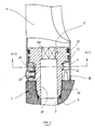
- the upper end of the fitting housing of a sanitary fitting is identified by the reference number 1.
- the precise structure of this sanitary fitting is of no importance in the present context. In particular, it does not matter whether the outflowing water is mixed water or pure cold or hot water; it is also irrelevant whether the sanitary fitting contains the controlling shut-off elements itself or whether it is a pure one Faucet outlet acts.
- the valve housing 1 is penetrated by an axial water channel 2, which widens in the upper area to a threaded opening 2a. From above, a receptacle 3 is screwed into the threaded opening 2a, to which a swivel spout 4 is pivotally attached in the manner described below.
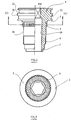
- the receptacle 3 is shown in isolation in FIGS. 2 and 3. This is referred to first.
- the receptacle 3 can be roughly divided into an upper area of larger diameter 3a and a lower area of smaller diameter 3b, at the transition of which an annular shoulder 5 pointing downward is formed.
- the lower area 3b of smaller diameter carries the screw-in thread 6, which cooperates with the threaded opening 2a of the valve body 1.
- a step 7 At the lowest end of the receptacle 3 there is a step 7, in which (see FIG. 1) an O-ring 8 is inserted, which serves to seal between the receptacle 3 and the fitting housing 1.
- the upper area 3a of larger diameter of the receptacle 3 is provided with two grooves 10, 11.
- the lower groove 10 receives a guide ring 12 (cf. FIG. 1), while an O-ring 13 (also shown in FIG. 1) lies in the upper groove 11.
- the entire recording 3 is traversed by a channel 14, which continues the water channel 2 in the fitting housing 1 and is designed in the upper region as a polygonal region 14a.
- a correspondingly shaped tool can be attached to the polygonal region 14a of the channel 14 when the receptacle 3 is screwed into the fitting housing 1.
- the swivel spout 4 is pushed over the receptacle 3 screwed into the fitting housing 1 in such a way that the inner lateral surface of its wall lies against both the O-ring 13 and the guide ring 12.
- a stop ring 15 is used, which serves several functions in a manner to be described.
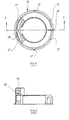
- the stop ring 15 is shown in more detail in FIGS. 4 and 5, to which reference is now made.
- the stop ring 15 as can be seen in particular in FIG. 4, is slotted at 16 so that it can resiliently bear against the region 3b of the receptacle 3. At regular intervals it bears radially protruding, axially parallel ribs 17 on the outer lateral surface. These are material areas which are plastically deformed, namely compressed, when the inner lateral surface of the swivel spout 4 is pushed over them. The ribs 17 thus serve to compensate for tolerances between the internal dimensions of the swivel spout 4 and the stop ring 15.
- the stop ring 15 is formed in a certain angular range with an arc-shaped, axially projecting stop projection 18, which with its upper end face on the ring shoulder 5 and with the upper end of its inner Shell surface abuts an outer cylindrical shell surface of the receptacle 3. In this way, the stop ring 15 ensures play-free radial mounting and axial securing of the swivel spout 4 on the receptacle 3. He is supported by the guide ring 12, on the outer lateral surface of which similar plastically deformable ribs are provided, as have already been described above with the reference number 17 on the stop ring 15.
- FIG. 1 shows, the swivel spout 4 placed over the receptacle 3 is fastened to the stop ring 15 by means of a screw 19.
- the stop ring 15 takes on the function of limiting the angle of rotation of the swivel spout 4 in addition to the mounting and mounting of the swivel spout 4 , the receptacle 3 and the inner circumferential surface of the swivel spout 4 limited annular space is plugged onto the toothing 9.
- the spatial relationships become particularly clear when considering FIGS. 1 and 8.
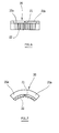
- Figures 6 and 7 show the stop piece 20 for itself. It can be seen particularly clearly from these figures that the stop piece 20 is composed of two parts 20a and 20b which are connected to one another via a predetermined breaking point 21.
- the stop piece 20 has on its inner circumferential surface a toothing 22 which is complementary to the external toothing 9 on the receptacle 3.
- the swivel spout 4 can be rotated by the maximum swivel angle; the pivoting movement comes to an end when the stop projection 18 of the stop ring 15 abuts against one of the two parts 20a or 20b of the stop piece 20.
- the maximum swivel angle of the swivel spout 4 is calculated as the difference between 360 ° and the sum of the two angles which are enclosed by the stop piece 20 and the stop projection 18.
- the swivel spout 4 can also be fixed non-rotatably in any angular position.
- the two parts 20a and 20b of the stop piece 20 are detached from one another at the predetermined breaking point 21. You are then placed separately on the teeth 9 of the receptacle 3 that they enclose the stop projection 18 in the correct angular position and in direct contact between them. The angular movement of the stop projection 18 and thus of the swivel spout 4 is then prevented in both directions by a part 20a, 20b of the stop piece 20.
- any conceivable intermediate state between a complete fixation of the swivel spout 4 and its maximum rotatability can be selected by a suitable choice of the angular position in which the parts 20a or 20b are fitted onto the toothing 9.
- swivel spouts of the type of interest here for example due to the overall fitting on which they are located, a middle position.
Landscapes
- Engineering & Computer Science (AREA)
- General Engineering & Computer Science (AREA)
- Health & Medical Sciences (AREA)
- Life Sciences & Earth Sciences (AREA)
- Hydrology & Water Resources (AREA)
- Public Health (AREA)
- Water Supply & Treatment (AREA)
- Mechanical Engineering (AREA)
- Domestic Plumbing Installations (AREA)
- Preventing Unauthorised Actuation Of Valves (AREA)
- Taps Or Cocks (AREA)
- Infusion, Injection, And Reservoir Apparatuses (AREA)
Claims (5)
- Appareil de robinetterie sanitaire à sortie orientable, aveca) un corps d'appareil de robinetterie, sur lequel la sortie orientable peut être emmanchée à pivotement,b) au moins une bague de guidage, servant de palier radial, entre la sortie orientable et le corps d'appareil de robinetterie ou une pièce assemblée à ce dernier,c) un moyen, sur la bague de guidage, qui permet de compenser des tolérances différentes en vue d'un montage sans jeu radial de la sortie orientable,caractérisé en ce que
d) ledit moyen sur la bague de guidage (15, 12) comprend des surélévations de matière (17) sur une face d'enveloppe qui peuvent être déformées plastiquement, mais non élastiquement, lors de l'emmanchement de la sortie orientable (4). - Appareil de robinetterie sanitaire selon la revendication 1, caractérisé en ce que les surélévations de matière sont des nervures (17) s'étendant axialement.
- Appareil de robinetterie sanitaire selon la revendication 1, caractérisé en ce que les surélévations de matière sont des noppes discrètes.
- Appareil de robinetterie sanitaire selon l'une des revendications précédentes, caractérisé en ce qu'une bague de guidage (15) portant des surélévations de matière (17) est conçue en même temps comme bague de butée pour limiter l'angle de pivotement de la sortie orientable (4).
- Appareil de robinetterie sanitaire selon l'une des revendications précédentes, caractérisé en ce que deux ou plusieurs bagues de guidage (15, 12) pourvues de surélévations de matière (17) sont prévues à distance axiale les unes des autres sur une face d'enveloppe.
Applications Claiming Priority (2)
| Application Number | Priority Date | Filing Date | Title |
|---|---|---|---|
| DE4102133 | 1991-01-25 | ||
| DE4102133A DE4102133C2 (de) | 1991-01-25 | 1991-01-25 | Sanitärarmatur mit Schwenkauslauf |
Publications (3)
| Publication Number | Publication Date |
|---|---|
| EP0496103A2 EP0496103A2 (fr) | 1992-07-29 |
| EP0496103A3 EP0496103A3 (en) | 1992-11-25 |
| EP0496103B1 true EP0496103B1 (fr) | 1997-03-26 |
Family
ID=6423660
Family Applications (1)
| Application Number | Title | Priority Date | Filing Date |
|---|---|---|---|
| EP91122087A Expired - Lifetime EP0496103B1 (fr) | 1991-01-25 | 1991-12-22 | Soupape sanitaire avec sortie orientable |
Country Status (4)
| Country | Link |
|---|---|
| EP (1) | EP0496103B1 (fr) |
| AT (1) | ATE150856T1 (fr) |
| DE (1) | DE4102133C2 (fr) |
| ES (1) | ES2100201T3 (fr) |
Cited By (1)
| Publication number | Priority date | Publication date | Assignee | Title |
|---|---|---|---|---|
| EP1507044A2 (fr) | 2003-08-13 | 2005-02-16 | Hansa Metallwerke Ag | Robinet sanitaire avec bec verseur pivotant |
Families Citing this family (4)
| Publication number | Priority date | Publication date | Assignee | Title |
|---|---|---|---|---|
| DE19508638C2 (de) * | 1995-03-10 | 1997-02-27 | Hansa Metallwerke Ag | Handbrause |
| DE19941820C1 (de) * | 1999-09-02 | 2001-02-08 | Hansa Metallwerke Ag | Sanitärarmatur |
| DE102013011708A1 (de) * | 2013-07-15 | 2015-01-15 | Hansa Metallwerke Ag | Radiallager-Ringelement und Sanitärarmatur mit einem solchen |
| CN107830217A (zh) * | 2017-10-16 | 2018-03-23 | 宁波欧琳厨具有限公司 | 水龙头 |
Family Cites Families (5)
| Publication number | Priority date | Publication date | Assignee | Title |
|---|---|---|---|---|
| DE2629795A1 (de) * | 1976-07-02 | 1978-01-05 | Hansa Metallwerke Ag | In einem ventilauslaufstutzen schwenkbar gelagertes auslaufrohr |
| DE2853052C2 (de) * | 1978-12-08 | 1982-10-07 | Hansa Metallwerke Ag, 7000 Stuttgart | Steuerkartusche für ein Ventil |
| DE2948474C2 (de) * | 1979-12-01 | 1983-11-17 | Friedrich Grohe Armaturenfabrik Gmbh & Co, 5870 Hemer | Sanitärarmatur mit schwenkbarem Auslaufarm |
| DE3509310A1 (de) * | 1985-03-15 | 1986-09-18 | Hans Grohe Gmbh & Co Kg, 7622 Schiltach | Schwenkrohrauslauf fuer armaturen |
| DE3815492C2 (de) * | 1988-05-06 | 1998-07-02 | Hackforth Gmbh & Co Kg | Verbindungssystem für ein zylindrisches metallisches Rohr |
-
1991
- 1991-01-25 DE DE4102133A patent/DE4102133C2/de not_active Expired - Fee Related
- 1991-12-22 ES ES91122087T patent/ES2100201T3/es not_active Expired - Lifetime
- 1991-12-22 AT AT91122087T patent/ATE150856T1/de not_active IP Right Cessation
- 1991-12-22 EP EP91122087A patent/EP0496103B1/fr not_active Expired - Lifetime
Cited By (4)
| Publication number | Priority date | Publication date | Assignee | Title |
|---|---|---|---|---|
| EP1507044A2 (fr) | 2003-08-13 | 2005-02-16 | Hansa Metallwerke Ag | Robinet sanitaire avec bec verseur pivotant |
| DE10337223A1 (de) * | 2003-08-13 | 2005-03-17 | Hansa Metallwerke Ag | Sanitärarmatur mit Schwenkauslauf |
| DE10337223B4 (de) * | 2003-08-13 | 2005-06-09 | Hansa Metallwerke Ag | Sanitärarmatur mit Schwenkauslauf |
| US7032619B2 (en) | 2003-08-13 | 2006-04-25 | Hansa Metallwerke Ag | Sanitary fitting with swivelling spout |
Also Published As
| Publication number | Publication date |
|---|---|
| DE4102133C2 (de) | 1997-08-21 |
| ATE150856T1 (de) | 1997-04-15 |
| DE4102133A1 (de) | 1992-07-30 |
| ES2100201T3 (es) | 1997-06-16 |
| EP0496103A2 (fr) | 1992-07-29 |
| EP0496103A3 (en) | 1992-11-25 |
Similar Documents
| Publication | Publication Date | Title |
|---|---|---|
| EP0731229B1 (fr) | Support de pomme de douche | |
| EP1501453B2 (fr) | Implant reglable en hauteur destine a etre insere entre des vertebres et outil de manipulation | |
| DE2038767C3 (de) | Schraubkupplung zum Befestigen eines Objektivs an einer Kamera | |
| DE4447366A1 (de) | Drehvorrichtung | |
| DE3843095C2 (de) | Befestigungseinrichtung für Verkleidungen | |
| DE19637074A1 (de) | Kupplungseinrichtung zur Verbindung zweier Rohrelemente | |
| DE3906959C1 (en) | Assembly device for automotive gear clutches | |
| EP0530471B1 (fr) | Dispositif de commande pour une soupape de mélange | |
| EP3428353A1 (fr) | Élément de retenue mural pour un article sanitaire | |
| EP0044904A2 (fr) | Thermostat pour régler la soupape d'un radiateur | |
| EP0496103B1 (fr) | Soupape sanitaire avec sortie orientable | |
| EP0683931B1 (fr) | Appareil de commande et/ou de signalisation | |
| EP4012200B1 (fr) | Boulon d'encliquetage sollicité par ressort | |
| EP0683341A2 (fr) | Armature sanitaire | |
| DE2823561A1 (de) | Messinstrument | |
| EP0955479B1 (fr) | Dispositif d'assemblage d'éléments de construction | |
| EP0303127A1 (fr) | Dispositif avec un élément de vis et élément d'écrou et utilisation du dispositif | |
| DE69404940T2 (de) | Einrichtung zum Festsetzen einer Schraube zur Steuerung der Neigung eines Scheinwerferreflektors | |
| DE4102132C1 (en) | Dewatering device partic for sludge of paper fibres - has system of horizontally dewatering rotating drum with screen form conveyor belt and pressure belt passing around drum at specific angle AB DE4101856C Sludge, partic. of paper fibres, is dewatered in an arrangement of a horizontally rotating dewatering drum (2) with a conveyor belt (3) in the form of a screen and a pressure belt (4), which pass round the drum with an arc of contact of 180 deg. max. Inlet (5) and outlet (6) drums are connected to the dewatering drum, the belts passing under these drums and over the dewatering drum, which is enclosed by a jacket with drainage channels. ADVANTAGE - Continuous dewatering with high efficiency is obtd.. AN 92235346 TI Sanitary fitting with swivelable outlet - has two stops, one with rated break point for separation into two independent parts | |
| EP2292447A2 (fr) | Crayon rotatif à roue libre | |
| DE3506121C2 (fr) | ||
| EP0718745A2 (fr) | Cuisinière à gaz avec unité de commutation | |
| DE2344621A1 (de) | Vorrichtung zum aufschrauben einer mutter mit innengewinde auf ein mit einem aussengewinde versehenes glied | |
| EP1649111A1 (fr) | Dispositif de retenue pour une douche | |
| EP0730911A1 (fr) | Douche à main |
Legal Events
| Date | Code | Title | Description |
|---|---|---|---|
| PUAI | Public reference made under article 153(3) epc to a published international application that has entered the european phase |
Free format text: ORIGINAL CODE: 0009012 |
|
| AK | Designated contracting states |
Kind code of ref document: A2 Designated state(s): AT CH ES FR GB IT LI |
|
| PUAL | Search report despatched |
Free format text: ORIGINAL CODE: 0009013 |
|
| AK | Designated contracting states |
Kind code of ref document: A3 Designated state(s): AT CH ES FR GB IT LI |
|
| 17P | Request for examination filed |
Effective date: 19930511 |
|
| 17Q | First examination report despatched |
Effective date: 19950111 |
|
| GRAG | Despatch of communication of intention to grant |
Free format text: ORIGINAL CODE: EPIDOS AGRA |
|
| GRAH | Despatch of communication of intention to grant a patent |
Free format text: ORIGINAL CODE: EPIDOS IGRA |
|
| GRAH | Despatch of communication of intention to grant a patent |
Free format text: ORIGINAL CODE: EPIDOS IGRA |
|
| GRAA | (expected) grant |
Free format text: ORIGINAL CODE: 0009210 |
|
| AK | Designated contracting states |
Kind code of ref document: B1 Designated state(s): AT CH ES FR GB IT LI |
|
| REF | Corresponds to: |
Ref document number: 150856 Country of ref document: AT Date of ref document: 19970415 Kind code of ref document: T |
|
| REG | Reference to a national code |
Ref country code: CH Ref legal event code: EP |
|
| REG | Reference to a national code |
Ref country code: CH Ref legal event code: NV Representative=s name: FREI PATENTANWALTSBUERO |
|
| ET | Fr: translation filed | ||
| ITF | It: translation for a ep patent filed | ||
| REG | Reference to a national code |
Ref country code: CH Ref legal event code: NV Representative=s name: FREI PATENTANWALTSBUERO |
|
| REG | Reference to a national code |
Ref country code: ES Ref legal event code: FG2A Ref document number: 2100201 Country of ref document: ES Kind code of ref document: T3 |
|
| GBT | Gb: translation of ep patent filed (gb section 77(6)(a)/1977) |
Effective date: 19970609 |
|
| PLBI | Opposition filed |
Free format text: ORIGINAL CODE: 0009260 |
|
| PLBF | Reply of patent proprietor to notice(s) of opposition |
Free format text: ORIGINAL CODE: EPIDOS OBSO |
|
| 26 | Opposition filed |
Opponent name: FRIEDRICH GROHE AKTIENGESELLSCHAFT Effective date: 19971212 |
|
| PLBF | Reply of patent proprietor to notice(s) of opposition |
Free format text: ORIGINAL CODE: EPIDOS OBSO |
|
| PLBO | Opposition rejected |
Free format text: ORIGINAL CODE: EPIDOS REJO |
|
| PLBN | Opposition rejected |
Free format text: ORIGINAL CODE: 0009273 |
|
| STAA | Information on the status of an ep patent application or granted ep patent |
Free format text: STATUS: OPPOSITION REJECTED |
|
| 27O | Opposition rejected |
Effective date: 19990516 |
|
| PGFP | Annual fee paid to national office [announced via postgrant information from national office to epo] |
Ref country code: GB Payment date: 19991222 Year of fee payment: 9 |
|
| PG25 | Lapsed in a contracting state [announced via postgrant information from national office to epo] |
Ref country code: GB Free format text: LAPSE BECAUSE OF NON-PAYMENT OF DUE FEES Effective date: 20001222 |
|
| GBPC | Gb: european patent ceased through non-payment of renewal fee |
Effective date: 20001222 |
|
| PGFP | Annual fee paid to national office [announced via postgrant information from national office to epo] |
Ref country code: ES Payment date: 20041214 Year of fee payment: 14 |
|
| PGFP | Annual fee paid to national office [announced via postgrant information from national office to epo] |
Ref country code: FR Payment date: 20041217 Year of fee payment: 14 Ref country code: CH Payment date: 20041217 Year of fee payment: 14 Ref country code: AT Payment date: 20041217 Year of fee payment: 14 |
|
| PG25 | Lapsed in a contracting state [announced via postgrant information from national office to epo] |
Ref country code: IT Free format text: LAPSE BECAUSE OF NON-PAYMENT OF DUE FEES;WARNING: LAPSES OF ITALIAN PATENTS WITH EFFECTIVE DATE BEFORE 2007 MAY HAVE OCCURRED AT ANY TIME BEFORE 2007. THE CORRECT EFFECTIVE DATE MAY BE DIFFERENT FROM THE ONE RECORDED. Effective date: 20051222 Ref country code: AT Free format text: LAPSE BECAUSE OF NON-PAYMENT OF DUE FEES Effective date: 20051222 |
|
| PG25 | Lapsed in a contracting state [announced via postgrant information from national office to epo] |
Ref country code: ES Free format text: LAPSE BECAUSE OF NON-PAYMENT OF DUE FEES Effective date: 20051223 |
|
| PG25 | Lapsed in a contracting state [announced via postgrant information from national office to epo] |
Ref country code: LI Free format text: LAPSE BECAUSE OF NON-PAYMENT OF DUE FEES Effective date: 20051231 Ref country code: CH Free format text: LAPSE BECAUSE OF NON-PAYMENT OF DUE FEES Effective date: 20051231 |
|
| REG | Reference to a national code |
Ref country code: CH Ref legal event code: PL |
|
| PG25 | Lapsed in a contracting state [announced via postgrant information from national office to epo] |
Ref country code: FR Free format text: LAPSE BECAUSE OF NON-PAYMENT OF DUE FEES Effective date: 20060831 |
|
| REG | Reference to a national code |
Ref country code: FR Ref legal event code: ST Effective date: 20060831 |
|
| REG | Reference to a national code |
Ref country code: ES Ref legal event code: FD2A Effective date: 20051223 |