EP0530659A1 - Electrode en alliage emmagasinant l'hydrogène et son procédé de fabrication - Google Patents
Electrode en alliage emmagasinant l'hydrogène et son procédé de fabrication Download PDFInfo
- Publication number
- EP0530659A1 EP0530659A1 EP92114519A EP92114519A EP0530659A1 EP 0530659 A1 EP0530659 A1 EP 0530659A1 EP 92114519 A EP92114519 A EP 92114519A EP 92114519 A EP92114519 A EP 92114519A EP 0530659 A1 EP0530659 A1 EP 0530659A1
- Authority
- EP
- European Patent Office
- Prior art keywords
- hydrogen storage
- storage alloy
- powder
- alloy electrode
- manufacturing
- Prior art date
- Legal status (The legal status is an assumption and is not a legal conclusion. Google has not performed a legal analysis and makes no representation as to the accuracy of the status listed.)
- Granted
Links
Images


Classifications
-
- H—ELECTRICITY
- H01—ELECTRIC ELEMENTS
- H01M—PROCESSES OR MEANS, e.g. BATTERIES, FOR THE DIRECT CONVERSION OF CHEMICAL ENERGY INTO ELECTRICAL ENERGY
- H01M4/00—Electrodes
- H01M4/02—Electrodes composed of, or comprising, active material
- H01M4/36—Selection of substances as active materials, active masses, active liquids
- H01M4/38—Selection of substances as active materials, active masses, active liquids of elements or alloys
- H01M4/383—Hydrogen absorbing alloys
-
- Y—GENERAL TAGGING OF NEW TECHNOLOGICAL DEVELOPMENTS; GENERAL TAGGING OF CROSS-SECTIONAL TECHNOLOGIES SPANNING OVER SEVERAL SECTIONS OF THE IPC; TECHNICAL SUBJECTS COVERED BY FORMER USPC CROSS-REFERENCE ART COLLECTIONS [XRACs] AND DIGESTS
- Y02—TECHNOLOGIES OR APPLICATIONS FOR MITIGATION OR ADAPTATION AGAINST CLIMATE CHANGE
- Y02E—REDUCTION OF GREENHOUSE GAS [GHG] EMISSIONS, RELATED TO ENERGY GENERATION, TRANSMISSION OR DISTRIBUTION
- Y02E60/00—Enabling technologies; Technologies with a potential or indirect contribution to GHG emissions mitigation
- Y02E60/10—Energy storage using batteries
Definitions
- the present invention relates to a hydrogen storage alloy electrode used as a negative electrode in, for example, a rechargeable battery and a method of manufacturing thereof.
- a nickel-hydride battery comprising a negative electrode formed of a hydrogen storage alloy, a positive electrode formed of nickel hydroxide, and an alkaline solution used as an electrolyte attracts attentions as a rechargeable battery having a high energy density and free from air pollution and water contamination problem.
- the hydrogen storage alloy used for forming the negative electrode includes, for example, rare earth and nickel system AB5 type alloy such as LaNi5 and MmNi5 (Mm: misch metal), titanium and nickel system alloy such as Ti2Ni and TiNi, and an alloy containing as a base material an alloy represented by formula AB2 and having a Laves phase.
- a pasted type method is generally used for manufacturing an electrode using a hydrogen storage alloy.
- a hydrogen storage alloy ingot is pulverized by a milling apparatus under the air atmosphere.
- the pulverized alloy is slurried in water together with a thickener and a binder to prepare a paste.
- porous substrate or perforated sheet made of metal is filled with the paste, followed by drying so as to obtain a desired electrode.
- the substrate or sheet is coated with the paste for manufacturing the desired electrode.
- Conventional method also includes a sintering method, in which a hydrogen storage alloy powder is sintered together with a metal net.
- the hydrogen storage alloy powder prepared by the conventional method is relatively low in its activity and, thus, the electrode prepared by using the hydrogen storage alloy thus prepared is relatively low in its discharge capacity.
- the discharge capacity of the hydrogen storage alloy is lowered during the preservation over a long period of time.
- layer made of chemically stable oxides of elements such as La, Ti and Zz are formed on the surface of the powdery particle of the hydrogen storage alloy in the step of pulverizing a hydrogen storage alloy ingot in a milling apparatus or the step of preserving the obtained hydrogen storage alloy powder.
- the oxide layers thus formed are considered to inhibit the electrode reaction, leading to the lowered discharge capacity noted above.
- polymers such as the thickener and binder cover the surface of the hydrogen storage alloy, resulting in a low reactivity on the surface of the hydrogen storage alloy.
- a thickener such as carboxymethyl cellulose (CMC), which is used in the step of preparing a paste using a water, is high in hydrophilic nature and, thus, the surface of the hydrogen storage alloy is uniformly wetted.
- the sintering method certainly permits diminishing the volume occupied by components other than the active materials.
- the surface of the hydrogen storage alloy is stained with, for example, oxides in the step of the heat treatment at high temperatures, leading to a low reactivity on the surface of the hydrogen storage alloy.
- An object of the present invention is to provide a a hydrogen storage alloy electrode capable of improving the reaction activity and maintaining a high discharge capacity over a long period of time and excellent in durability and preservation capability, and to provide a method of manufacturing thereof capable to readily manufacture a hydrogen storage alloy electrode.
- a method of manufacturing a hydrogen storage alloy electrode having the steps of: mixing a hydrogen storage alloy powder with a powder of at least one metal to obtain a mixed powder; milling the mixed powder in a milling apparatus with a closed system to obtain a milled powdery mixture; and preparing a hydrogen storage alloy electrode by using the milled powdery mixture.
- the present invention also provides a hydrogen storage alloy electrode having a conductive substrate, and a mixed powder, which includes a hydrogen storage alloy powder and a powder of at least one metal, disposed directly on the conductive substrate by means of the pressure molding, wherein the mixed powder is obtained by milling in a milling apparatus with a closed system.
- coarse particles having an average particle diameter of 1 millimeter to several millimeters can be used in the present invention.
- oxidation of the hydrogen storage alloy in pulverizing step can be suppressed effectively, making it possible to obtain a hydrogen storage alloy electrode with a further improved activity.
- the metal used in the present invention together with the hydrogen storage alloy includes, for example, copper, nickel, cobalt, aluminum, silver, palladium, gold, platinum, tin and antimony.
- the metal used in the present invention may be a powder having an average particle diameter of about 0.1 ⁇ m or a coarse powder having an average particle diameter of 1 to several millimeters.
- a stainless steel ball mill, atlighter, etc. may be used in the present invention as a milling apparatus with a closed system.
- the binder which is added to a milled powdery mixture in the present invention includes, for example, a polytetrafluroethylene powder, a polyvinylidene fluoride powder, etc.
- the binder should desirably be added to the milled powdery mixture in an amount of not more than 1.5% by weight. If the amount of the binder exceeds 1.5% by weight, the amount of the hydrogen storage alloy powder filled in the substrate for electrode is to be small.
- the hydrogen storage alloy electrode In order to improve the mechanical strength of the hydrogen storage alloy electrode, it is desirable to apply a heat treatment at not higher than 1100°C after the pressure molding step. If the temperature for the heat treatment exceeds 1100°C, the metal coated on the surface of the hydrogen storage alloy particle is diffused into the inside of the particle. Alternatively, the hydrogen storage alloy is oxidized hardly by the impure oxygen in the system.
- a natural oxide film is formed on the surface of the powdery particle of the hydrogen storage alloy.
- the natural oxide film is broken or peeled off by the mechanical impact in the step of milling the mixed powder in a milling apparatus.
- the powdery particles of the metal added to the hydrogen storage alloy are strongly pressed against the hydrogen storage alloy particles, with the result that at least a part of the surfaces of the hydrogen storage alloy particles are covered with the metal in place of the oxide film.
- the milled powdery mixture prepared in the present invention exhibits a high discharge capacity with a smaller number of charge/discharge cycling.
- the hydrogen storage alloy is prevented from oxidation, making it possible to preserve the milled powdery mixture of the hydrogen storage alloy over a long period of time.
- the hydrogen storage alloy is in the form of a coarse powder having an average particle diameter of 1 millimeter to several millimeter
- the alloy is less likely to be oxidized by the air because the specific surface area of the coarse powder is smaller than that of a fine powder. It follows that it is possible to obtain a milled powdery mixture having a higher activity in the case of using a coarse powder.
- the milling treatment is carried out in a milling apparatus with a closed system, not in an open apparatus such as a mortar.
- the hydrogen storage alloy particles are prevented from oxidation during the period ranging between the peeling of the natural oxide film from the particle and the covering of the particle surface with the metal, leading to an improved activity on the surface of the hydrogen storage alloy particle.
- the hydrogen storage alloy electrode obtained by using this milled powdery mixture exhibits high discharge capacity.
- the milling treatment within a closed system also permits controlling the oxidation of the hydrogen storage alloy powder.
- a hydrogen storage alloy has a high hardness, making it difficult to have the alloy attached to another material by applying pressure.
- a heat treatment at about 1100°C is applied together with the pressure molding in the conventional sintering method.
- the hydrogen storage alloy particles covered with the metal as in the present invention exhibit a high adhesiveness, making it possible to obtain an electrode sheet of a considerably high mechanical strength by the pressure molding method. Even in this case, it is desirable to apply a heat treatment for improving the mechanical strength of the electrode sheet. Small alloy particles covered with the metal have a high surface energy, with the result that the alloy particles are sufficiently bonded to each other even at a relatively low temperature. Further, an electrode sheet having a high mechanical strength can be effectively prepared by the hot pressing treatment.
- the oxidation rate is lowered so as to suppress the oxidation on the surface of the hydrogen storage alloy particle.
- metal oxides such as nickel oxide or copper oxide are readily reduced electrochemically within an alkaline electrolyte.
- the metal oxide even if formed on the surface of the alloy particle, is reduced into the metal in the charge process.
- the hydrogen storage alloy particles covered with, particularly, nickel or copper exhibit a high reactivity even if a metal oxide is formed in the heating step.
- the heat treatment is carried out at a temperature higher than 1100°C, the metal covering the alloy particle such as nickel or copper is diffused into the hydrogen storage alloy particle so as to form an alloy. It follows that it is necessary to avoid the heat treatment at a temperature higher than 1100°C.
- a powdery material of a polymer binder such as polytetrafluoroethylene (PTFE) or polyvinylidene fluoride (PDVF)
- PTFE polytetrafluoroethylene
- PDVF polyvinylidene fluoride
- a milling apparatus is used in the mixing step, a sufficient mechanical strength can be obtained even if the amount of the binder is 1.5% by weight or less because the mixed powder exhibits a high adhesiveness. In other words, it is possible to diminish the volume occupied by the binder in the hydrogen storage alloy electrode.
- a mixed powder was prepared by adding 2.8g of a nickel powder having an average particle diameter of 0.3 ⁇ m to 20g of a hydrogen storage alloy powder prepared by pulverizing an ingot of Zr-containing Laves phase alloy of Zr 0.9 Ti 0.1 (V 0.33 Ni 0.51 Co 0.08 Mn 0.08 ) 2.4 to have an average particle diameter of about 1 mm.
- the mixed powder was milled for 1 hour under the air atmosphere within a stainless steel ball mill so as to obtain a milled powdery mixture consisting of the hydrogen storage alloy and nickel.
- the milled powdery mixture was found to have a particle diameter of less than 63 ⁇ m, and at least a part of the hydrogen storage alloy particle was covered with nickel.
- Example 1 a disk-like hydrogen storage alloy electrode having a diameter of 20 mm.
- Example 2 A milled powdery mixture consisting of a hydrogen storage alloy and nickel was prepared as in Example 1, except that the milling treatment was carried out for 5 hours. Then, a hydrogen storage alloy electrode (Example 2) was prepared as in Example 1 by using the milled powdery mixture thus prepared.
- a mixed powder was prepared by adding 2.8g of a copper powder having an average particle diameter of 0.8 to 1.2 ⁇ m to 20g of the hydrogen storage alloy powder equal to that used in Example 1.
- the mixed powder was milled for 1 hour under the air atmosphere within a stainless steel ball mill so as to obtain a milled powdery mixture consisting of the hydrogen storage alloy and copper.
- the milled powdery mixture was found to have an average particle diameter of 63 ⁇ m, and at least a part of the hydrogen storage alloy particle was covered with copper.
- a hydrogen storage alloy electrode (Example 3) was prepared as in Example 1 by using the milled powdery mixture thus prepared.
- Example 4 A milled powdery mixture consisting of a hydrogen storage alloy and copper was prepared as in Example 1, except that the milling treatment was carried out for 5 hours. Then, a hydrogen storage alloy electrode (Example 4) was prepared as in Example 1 by using the milled powdery mixture thus prepared.
- a hydrogen storage alloy powder having an average particle diameter of less than 63 ⁇ m was prepared by milling 20g of the hydrogen storage alloy powder equal to that used in Example 1. The milling treatment was carried out for 1 hour under the air atmosphere within a stainless steel ball mill. Then, 2.8g of a nickel powder having an average particle diameter of 0.2 ⁇ m was added to the hydrogen storage alloy powder thus prepared. The resultant mixture was put in a plastic bottle, and a mixed powder consisting of the hydrogen storage alloy and nickel was prepared by vibrating the bottle. A hydrogen storage alloy electrode (Prior Art 1) was prepared as in Example 1 by using the mixed powder.
- Milled mixtures were prepared as in Examples 1 to 4, except that a mortar was used in place of the ball mill. Hydrogen storage alloy electrodes (Controls 1 to 4) were prepared as in Example 1 by using these milled mixtures.
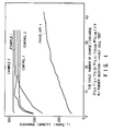
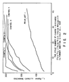
- Figs. 1 and 2 show the results.
- a cell was prepared by using the hydrogen storage alloy electrode to which a lead wire was attached as a negative electrode and a nickel plate as a counter electrode. These electrodes were immersed in an electrolyte solution containing 30% by weight of potassium hydroxide.
- the maximum discharge capacity was measured by performing the charge/discharge cycling the cell with a current of 70 mA per gram of the hydrogen storage alloy.
- the discharge stop potential was set at -0.75V vs Hg/HgO, and the charging time was set at 1.3 times as long as the discharging time.
- the hydrogen storage alloy electrodes for Examples 1 to 4 exhibited a discharge capacity markedly higher than that for Prior Art 1. Also, more than 40 cycles of the charge/discharge were required in Prior Art 1 before the maximum discharge capacity was arrived at. In Examples 1 to 4, however, the maximum discharge capacity was reached before 10 cycles of the charge/discharge.
- Fig. 1 also shows that the hydrogen storage alloy electrodes for Examples 1 and 2 were smaller in the cycling number of charge/discharge required for reaching the maximum discharge capacity than those for Controls 1 and 2, and exhibit high discharge capacity.
- Fig. 2 shows that the hydrogen storage alloy electrodes for Examples 3 and 4 were smaller in the cycling number of charge/discharge required for reaching the maximum discharge capacity than those for Controls 3 and 4, and exhibit high discharge capacity.
- the oxide film formed on the surface of the hydrogen storage alloy powder particle is removed in the milling step in the case of the hydrogen storage alloy powder prepared by the method of the present invention. Since the surface of the alloy particle is covered with another metal such as copper or nickel in place of the oxide film, the activity of the hydrogen storage alloy is markedly improved in the present invention. It follows that the hydrogen storage alloy electrode of the present invention prepared by using a milled powdery mixture exhibits a high discharge capacity immediately after the operation, compared with the conventional hydrogen storage alloy electrode. In addition, the electrode of the present invention permits markedly diminishing the cycling number of charge/discharge required for reaching the maximum discharge capacity. The experimental data given in Figs. 1 and 2 also show that the activity and discharge capacity of the hydrogen storage alloy electrode of the present invention can be further improved with increase in the milling time in the step of preparing the milled powdery mixture.
- milled powdery mixtures were prepared by adding respectively a cobalt powder, a mixture of cobalt powder and a nickel powder, a mixture of cobalt powder and a copper powder, and a mixture of a nickel powder, a cobalt powder and a copper powder to a hydrogen storage alloy powder, as in the Examples described above. Then, hydrogen storage alloy electrodes were prepared by using these milled powdery mixtures. The maximum discharge capacity and the cycling number of charge/discharge were measured as described previously, obtaining results similar to those shown in Figs. 1 and 2.
- AA size sealed cell were prepared by using the hydrogen storage alloy electrodes prepared in Examples 1-4, Controls 1-4, and Prior Art 1 as negative electrodes, known nickel hydroxide electrodes having a capacity of 1300 mAh as positive electrodes, and separators.
- a mixture consisting of 99.5 parts by weight of the mixed Powder and 0.5 part by weight of polytetrafluoroethylene was kneaded, followed by rolling the kneaded mixture to prepare a sheet. Then, the sheet was laminated on a nickel net, followed by rolling the resultant laminate structure and subsequently cutting the rolled laminate structure in a predetermined size so as to obtain the negative electrode.
- the cells thus prepared were subjected to the charge/discharge cycling with a current of 0.2 C (260 mA).
- the charging was set at 150% of the design capacity (nickel electrode capacity of 1300 mAh), and the discharge stop voltage was set at 1.00V.
- the relationship between the cycling number of charge/discharge in the initial stage and the discharge capacity was measured for each of the cells thus prepared, with the results as shown in Figs. 3 and 4.
- the cells using the hydrogen storage alloy electrodes for Examples 1-4 exhibited a large initial discharge capacity. It is seen that the design discharge capacity of 1300 mAh was reached before 20 cycles of the charge/discharge. When it comes to the cell prepared by using the hydrogen storage alloy electrode of Prior Art 1, however, the discharge capacity was increased very slowly with increase in the cycling number of the charge/discharge. The discharge capacity was only about 100 mAh even after 40 cycles of the charge/discharge.
- the cells prepared by using the hydrogen storage alloy electrodes of Controls 1-4 exhibited initial discharge capacities larger than that of the cell prepared by using the hydrogen storage alloy electrode of Prior Art 1.
- the cells for Controls 1-4 were markedly smaller in the discharge capacity than those of Examples 1-4, failing to reach the design capacity of 1300 mAh.
- a cell was prepared as above by using as a hydrogen storage alloy a Laves phase alloy of Zr 0.9 Ti 0.1 (V 0.33 Ni 0.51 Fe 0.08 Mn 0.08 ) 2.4 .
- the relationship between the cycling number of charge/discharge in the initial stage and the discharge capacity was measured for the cell thus prepared.
- the initial discharge capacity was found to be as large as that of the cells using the hydrogen storage alloy electrodes of Examples 1-4. It was also recognized that the design capacity of 1300 mAh was reached before 20 cycles of the charge/discharge.
- a mixed powder was prepared by adding 2.8g of a nickel powder having an average particle diameter of 0.2 ⁇ m to 20g of a hydrogen storage alloy powder prepared by pulverizing an ingot of a misch metal and nickel system alloy of MmNi 4.0 Co 0.5 Al5 to have an average particle diameter of about 1 mm.
- the mixed powder was milled for 1 hour under the air atmosphere within a stainless steel ball mill so as to obtain a milled powdery mixture consisting of the hydrogen storage alloy and nickel.
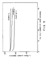
- Fig. 5 shows the results. As apparent from Fig. 5, the discharge capacities of the hydrogen storage alloy electrodes for Examples 5 and 6 were maintained at 250 mAhg ⁇ 1 to 260 mAhg ⁇ 1 in contrast to only 230 mAhg ⁇ 1 for Prior Art 2.
- Example 7 20g of the hydrogen storage alloy coarse grains equal to those used in Example 7 was milled for 5 hours under the air atmosphere in a stainless steel ball mill so as to obtain a hydrogen storage alloy powder having an average particle diameter not larger than 63 ⁇ m. Then, a mixture consisting of the hydrogen storage alloy powder and 2.8g of each of the metal powders shown in Table 1, each having an average particle diameter of 0.3 mm, was put in a plastic bottle. A mixed powder was prepared by vibrating the bottle. Further, a hydrogen storage alloy electrode was prepared as in Example 7 by using the mixed powder (Test Nos. 3, 4, 7, 8, 11 and 12 shown in Table 1).
- a cell was prepared by using the hydrogen storage alloy electrode prepared in each of Example 7 and Control 5, to which a lead wire was attached, as a negative electrode and a nickel plate as a counter electrode. These electrodes were immersed in an electrolyte solution containing 30% by weight of potassium hydroxide. The cell was performed the charge/discharge cycling three times with a current of 70 mA per gram of the hydrogen storage alloy. The discharge stop potential was set at -0.75V vs Hg/HgO, and the charging time was set at 1.3 times as long as the discharging time. The discharge capacity for every cycle of the charge/discharge was measured, with the results as shown in Table 1.
- a hydrogen storage alloy electrode was prepared by using the milled powdery mixture five months after preparation in Example 7, which was left under the air atmosphere.
- a hydrogen storage alloy electrode was prepared by using the mixed powder five months after preparation in Control 5, which was left under the air atmosphere.
- the discharge capacity for every cycle of the charge/discharge was measured for each of these electrodes, with the results as shown in Table 1.
- the term "Leaving Time” in Table 1 denotes the period between the pulverization of the hydrogen storage alloy and the initial charging of the hydrogen storage alloy electrode prepared by using the pulverized alloy.
- the hydrogen storage alloy electrode prepared by the method of the present invention exhibits a large discharge capacity.
- the electrode exhibits a large discharge capacity even in the case of using a milled powdery mixture long time after the preparation (Test Nos. 1-12 shown in Table 1).
- the milled powdery mixture prepared in the present invention exhibits a very high preservation capability (compare Test Nos. 1 and 2; 5 and 6; 9 and 10; 13 and 14; 15 and 16; 17 and 18; 19 and 20; 21 and 22; 23 and 24; 25 and 26).
- the milled powdery mixture prepared by the method of the present invention can be preserved over a long period of time.
- a hydrogen storage alloy electrode can be prepared easily and stably. Further, the hydrogen storage alloy electrode can be preserved over a long period of time.
- the hydrogen storage alloy electrode prepared by using a hydrogen storage alloy powder having a large average particle diameter exhibits a large discharge capacity. It is considered reasonable to understand that coarse particles, which have a relatively small specific surface area, are less likely to be oxidized, leading to a large discharge capacity noted above.
- Example described above used was a MmNi-based alloy as a hydrogen storage alloy. Similar effects were also recognized in the cases of using titanium and nickel system alloy such as Ti2Ni and TiNi, a Zr-based Laves phase alloy, etc.
- a milled powdery mixture was pressed against a substrate as in Example 8, followed by applying a hot-press treatment to the resultant structure at 350°C while evacuating the system by a rotary pump so as to obtain a hydrogen storage alloy electrode sheet.
- a milled powdery mixture was prepared as in Example 8, followed by adding a PTFE dispersion and a CMC dispersion to the mixture so as to obtain a paste.
- a substrate as used in Example 8 was coated with the paste thus prepared, followed by drying and, then, applying pressure molding to the resultant structure as in Example 8 so as to obtain a hydrogen storage alloy electrode sheet.
- An alloy powder was pressed against a substrate as in Control 6, followed by applying a heat treatment to the resultant structure while evacuating the system by a rotary pump.
- the heat treatment was performed at 350°C for 3 hours (Control 7), at 600°C for 3 hours (Control 8), and at 1100°C for 3 hours (Control 9) so as to obtain hydrogen storage alloy electrode sheets.
- a mixed powder consisting of 96 parts by weight of an alloy powder having an average particle diameter of about 63 ⁇ m, which was obtained by pulverizing a Zr 0.9 Ti 0.1 (V 0.33 Ni 0.51 Co 0.08 Mn 0.08 ) 2.4 alloy, and 4 parts by weight of a nickel powder. Then, the mixed powder was pressed against a substrate as in Control 6 so as to obtain a hydrogen storage alloy electrode sheet.
- a mixed powder was pressed against a substrate as in Control 10, followed by applying a heat treatment to the resultant structure while evacuating the system by a rotary pump.
- the heat treatment was performed at 350°C for 3 hours (Control 11), at 600°C for 3 hours (Control 12), and at 1100°C for 3 hours (Control 13) so as to obtain hydrogen storage alloy electrode sheets.
- the maximum discharge capacity, the cycling number of charge/discharge leading to 10% reduction in the discharge capacity, and the electrode state (durability) were examined with respect to each of the hydrogen storage alloy electrodes prepared in Examples 8-13 and Controls 6-13.
- the results are shown in Table 3.
- a cell was prepared by using the hydrogen storage alloy electrode sheet, to which a lead wire was attached, as a negative electrode and a nickel plate as a counter electrode. These electrodes were immersed in an electrolyte solution containing 30% by weight of potassium hydroxide, and the cell was performed the charge/discharge cycling with a current of 70 mA per gram of the hydrogen storage alloy.
- the discharge stop potential was set at -0.75V vs Hg/HgO, and the charging time was 1.3 times as long as the discharging time.
- the discharge capacity was increased in the initial stage and, then, was gradually lowered with increase in the charge/discharge cycling in any of the electrodes.
- a mixture consisting of 96 parts by weight of an alloy powder having an average particle diameter of about 63 ⁇ m, which was prepared by pulverizing an alloy of Zr 0.9 Ti 0.1 (V 0.33 Ni 0.51 Co 0.08 Mn 0.08 ) 2.4 , and 4 parts by weight of a nickel powder was milled in a stainless steel ball mill for 5 hours under the air atmosphere so as to obtain a milled powdery mixture. Then, 1.5% by weight of a PTFE powder was added to the milled powdery mixture, followed by pressing 1g of the resultant powdery mixture against a substrate of a circular nickel net having an outer diameter of 20 mm under a pressure of 3 tons/cm2 so as to obtain a hydrogen storage alloy electrode sheet.
- a hydrogen storage alloy electrode sheet was prepared by applying a heat treatment at 200°C for 2 hours under a reduced pressure to a hydrogen storage alloy electrode sheet equal to that of Example 14 so as to obtain a hydrogen storage alloy electrode sheet.
- a mixed powder was prepared by adding 1.5% by weight of a PTFE powder to 1g of an alloy powder having an average particle diameter of about 63 ⁇ m, which was prepared in advance by pulverizing an alloy of Zr 0.9 Ti 0.1 (V 0.33 Ni 0.51 Co 0.08 Mn 0.08 ) 2.4 . Then, the mixed powder was pressed against a substrate of a circular nickel net having an outer diameter of 20 mm under a pressure of 3 tons/cm2 so as to prepare a hydrogen storage alloy electrode sheet.
- a hydrogen storage alloy electrode sheet was prepared as in Control 14, except that 3% by weight of a PTFE powder was added to the hydrogen storage alloy powder in preparing the mixed powder.
- the alloy dropping from the electrode was scarcely recognized during the charge/discharge cycling in the hydrogen storage alloy electrode sheets for Examples 14-16.
- a 10% reduction in the discharge capacity was not recognized even when the charge/discharge cycling were repeatedly carried out 200 times.
- the electrode sheets for Examples 14-16 exhibited a high discharge capacity.
- the alloy dropping from the electrode was recognized during the charge/discharge cycling, leading to a small discharge capacity, in the hydrogen storage alloy electrode sheets for Controls 14 and 15 in which a mixed powder consisting of a hydrogen storage alloy powder and a PTFE powder was pressed against a substrate for preparing the hydrogen storage alloy electrode sheet.
- the alloy dropping was also recognized in Control 16 in which a mixed powder prepared by simply mixing a nickel powder and a PTFE powder with a hydrogen storage alloy powder was pressed against a substrate for preparing the hydrogen storage alloy electrode sheet.
- the discharge capacity was small in Control 16.
- the amount of the PTFE powder was increased to 3% by weight. In this case, the electrode exhibited a satisfactory durability, but was small in the discharge capacity.
- the hydrogen storage alloy exhibits a high reactivity over a long period of time.
- the hydrogen storage alloy electrode prepared by the method of the present invention exhibits a high discharge capacity over a long period of time.
- the electrode is excellent in its durability and preservation capability.
Landscapes
- Chemical & Material Sciences (AREA)
- Chemical Kinetics & Catalysis (AREA)
- Electrochemistry (AREA)
- General Chemical & Material Sciences (AREA)
- Battery Electrode And Active Subsutance (AREA)
Applications Claiming Priority (6)
| Application Number | Priority Date | Filing Date | Title |
|---|---|---|---|
| JP298612/91 | 1991-08-29 | ||
| JP29861291 | 1991-08-29 | ||
| JP354180/91 | 1991-11-19 | ||
| JP3354180A JPH05343053A (ja) | 1991-08-29 | 1991-11-19 | 水素吸蔵合金電極並に電極用ミル処理混合粉 |
| JP14442592 | 1992-06-04 | ||
| JP144425/92 | 1992-06-04 |
Publications (2)
| Publication Number | Publication Date |
|---|---|
| EP0530659A1 true EP0530659A1 (fr) | 1993-03-10 |
| EP0530659B1 EP0530659B1 (fr) | 1997-11-05 |
Family
ID=27318820
Family Applications (1)
| Application Number | Title | Priority Date | Filing Date |
|---|---|---|---|
| EP92114519A Expired - Lifetime EP0530659B1 (fr) | 1991-08-29 | 1992-08-26 | Procédé de fabrication d'un electrode en alliage emmagasinant l'hydrogène |
Country Status (3)
| Country | Link |
|---|---|
| EP (1) | EP0530659B1 (fr) |
| CA (1) | CA2077172A1 (fr) |
| DE (1) | DE69223008T2 (fr) |
Cited By (12)
| Publication number | Priority date | Publication date | Assignee | Title |
|---|---|---|---|---|
| EP0591606A1 (fr) * | 1992-10-09 | 1994-04-13 | Matsushita Electric Industrial Co., Ltd. | Accumulateur alcalin et procédé de production d'un alliage emmagasinant l'hydrogène pour celui-ci |
| EP0647973A1 (fr) * | 1993-10-06 | 1995-04-12 | Sanyo Electric Co., Ltd. | Eléctrode en alliage absorbant l'hydrogène et procédé de fabrication |
| WO1997008439A1 (fr) * | 1995-08-31 | 1997-03-06 | Isad Electronic Systems Gmbh & Co. Kg | Systeme d'entrainement avec moteur d'entrainement, moteur electrique et batterie |
| EP0725983A4 (fr) * | 1993-10-08 | 1999-11-10 | Electro Energy Inc | Accumulateur electrochimique bipolaire forme par l'empilage d'elements a plaques |
| US6138629A (en) * | 1995-08-31 | 2000-10-31 | Isad Electronic Systems Gmbh & Co. Kg | System for actively reducing radial vibrations in a rotating shaft, and method of operating the system to achieve this |
| US6149544A (en) * | 1995-08-31 | 2000-11-21 | Isad Electronic Systems Gmbh & Co. Kg | Drive system for a motor vehicle with a drive unit and electric machine, and method of operating the system |
| US6148784A (en) * | 1995-08-31 | 2000-11-21 | Isad Electronic Systems Gmbh & Co. Kg | Drive systems, especially for a motor vehicle, and method of operating same |
| US6158405A (en) * | 1995-08-31 | 2000-12-12 | Isad Electronic Systems | System for actively reducing rotational nonuniformity of a shaft, in particular, the drive shaft of an internal combustion engine, and method of operating the system |
| US6487998B1 (en) | 1995-08-31 | 2002-12-03 | Isad Electronic Systems Gmbh & Co., Kg | Drive system, particularly for a motor vehicle, and process for operating it |
| US6503658B1 (en) | 2001-07-11 | 2003-01-07 | Electro Energy, Inc. | Bipolar electrochemical battery of stacked wafer cells |
| EP0851515A3 (fr) * | 1996-12-27 | 2004-10-27 | Canon Kabushiki Kaisha | Matière pulvérulente, électrode, accumulateur et procédé de fabrication |
| CN111519051A (zh) * | 2020-04-21 | 2020-08-11 | 上海申核能源工程技术有限公司 | 一种核设施事故后用吸氢材料配置工艺 |
Families Citing this family (1)
| Publication number | Priority date | Publication date | Assignee | Title |
|---|---|---|---|---|
| DE19532129A1 (de) | 1995-08-31 | 1997-03-06 | Clouth Gummiwerke Ag | System zur aktiven Verringerung von Drehungleichförmigkeiten einer Welle, insbesondere der Triebwelle eines Verbrennungsmotors, und Verfahren hierzu |
Citations (6)
| Publication number | Priority date | Publication date | Assignee | Title |
|---|---|---|---|---|
| EP0251384A1 (fr) * | 1986-06-26 | 1988-01-07 | Koninklijke Philips Electronics N.V. | Cellule electrochimique |
| US4728586A (en) * | 1986-12-29 | 1988-03-01 | Energy Conversion Devices, Inc. | Enhanced charge retention electrochemical hydrogen storage alloys and an enhanced charge retention electrochemical cell |
| FR2623271A1 (fr) * | 1987-11-17 | 1989-05-19 | Khuochih Kong | Procede de stockage d'hydrogene et materiaux pour electrodes d'hydrure |
| US4859413A (en) * | 1987-12-04 | 1989-08-22 | The Standard Oil Company | Compositionally graded amorphous metal alloys and process for the synthesis of same |
| EP0440843A1 (fr) * | 1988-09-22 | 1991-08-14 | Energy Conversion Devices, Inc. | Réacteur à hydrures pour la pulvérisation par hydrogène de matériau destiné à l'emmagasineage d'hydrogène, constitué d'hydrures métalliques |
| EP0293660B1 (fr) * | 1987-05-15 | 1993-06-16 | Matsushita Electric Industrial Co., Ltd. | Electrodes emmagasinant l'hydrogène |
-
1992
- 1992-08-26 EP EP92114519A patent/EP0530659B1/fr not_active Expired - Lifetime
- 1992-08-26 DE DE69223008T patent/DE69223008T2/de not_active Expired - Fee Related
- 1992-08-28 CA CA002077172A patent/CA2077172A1/fr not_active Abandoned
Patent Citations (6)
| Publication number | Priority date | Publication date | Assignee | Title |
|---|---|---|---|---|
| EP0251384A1 (fr) * | 1986-06-26 | 1988-01-07 | Koninklijke Philips Electronics N.V. | Cellule electrochimique |
| US4728586A (en) * | 1986-12-29 | 1988-03-01 | Energy Conversion Devices, Inc. | Enhanced charge retention electrochemical hydrogen storage alloys and an enhanced charge retention electrochemical cell |
| EP0293660B1 (fr) * | 1987-05-15 | 1993-06-16 | Matsushita Electric Industrial Co., Ltd. | Electrodes emmagasinant l'hydrogène |
| FR2623271A1 (fr) * | 1987-11-17 | 1989-05-19 | Khuochih Kong | Procede de stockage d'hydrogene et materiaux pour electrodes d'hydrure |
| US4859413A (en) * | 1987-12-04 | 1989-08-22 | The Standard Oil Company | Compositionally graded amorphous metal alloys and process for the synthesis of same |
| EP0440843A1 (fr) * | 1988-09-22 | 1991-08-14 | Energy Conversion Devices, Inc. | Réacteur à hydrures pour la pulvérisation par hydrogène de matériau destiné à l'emmagasineage d'hydrogène, constitué d'hydrures métalliques |
Cited By (15)
| Publication number | Priority date | Publication date | Assignee | Title |
|---|---|---|---|---|
| US5389468A (en) * | 1992-10-09 | 1995-02-14 | Matsushita Electric Industrial Co., Ltd. | Alkaline storage battery |
| EP0591606A1 (fr) * | 1992-10-09 | 1994-04-13 | Matsushita Electric Industrial Co., Ltd. | Accumulateur alcalin et procédé de production d'un alliage emmagasinant l'hydrogène pour celui-ci |
| EP0647973A1 (fr) * | 1993-10-06 | 1995-04-12 | Sanyo Electric Co., Ltd. | Eléctrode en alliage absorbant l'hydrogène et procédé de fabrication |
| US5529857A (en) * | 1993-10-06 | 1996-06-25 | Sanyo Electric Co., Ltd. | Hydrogen-absorbing alloy electrode and process for producing the same |
| EP0725983A4 (fr) * | 1993-10-08 | 1999-11-10 | Electro Energy Inc | Accumulateur electrochimique bipolaire forme par l'empilage d'elements a plaques |
| US6138629A (en) * | 1995-08-31 | 2000-10-31 | Isad Electronic Systems Gmbh & Co. Kg | System for actively reducing radial vibrations in a rotating shaft, and method of operating the system to achieve this |
| WO1997008439A1 (fr) * | 1995-08-31 | 1997-03-06 | Isad Electronic Systems Gmbh & Co. Kg | Systeme d'entrainement avec moteur d'entrainement, moteur electrique et batterie |
| US6149544A (en) * | 1995-08-31 | 2000-11-21 | Isad Electronic Systems Gmbh & Co. Kg | Drive system for a motor vehicle with a drive unit and electric machine, and method of operating the system |
| US6148784A (en) * | 1995-08-31 | 2000-11-21 | Isad Electronic Systems Gmbh & Co. Kg | Drive systems, especially for a motor vehicle, and method of operating same |
| US6158405A (en) * | 1995-08-31 | 2000-12-12 | Isad Electronic Systems | System for actively reducing rotational nonuniformity of a shaft, in particular, the drive shaft of an internal combustion engine, and method of operating the system |
| US6487998B1 (en) | 1995-08-31 | 2002-12-03 | Isad Electronic Systems Gmbh & Co., Kg | Drive system, particularly for a motor vehicle, and process for operating it |
| EP0851515A3 (fr) * | 1996-12-27 | 2004-10-27 | Canon Kabushiki Kaisha | Matière pulvérulente, électrode, accumulateur et procédé de fabrication |
| US6503658B1 (en) | 2001-07-11 | 2003-01-07 | Electro Energy, Inc. | Bipolar electrochemical battery of stacked wafer cells |
| US6887620B2 (en) | 2001-07-11 | 2005-05-03 | Electro Energy, Inc. | Bipolar electrochemical battery of stacked wafer cells |
| CN111519051A (zh) * | 2020-04-21 | 2020-08-11 | 上海申核能源工程技术有限公司 | 一种核设施事故后用吸氢材料配置工艺 |
Also Published As
| Publication number | Publication date |
|---|---|
| EP0530659B1 (fr) | 1997-11-05 |
| DE69223008D1 (de) | 1997-12-11 |
| DE69223008T2 (de) | 1998-03-26 |
| CA2077172A1 (fr) | 1993-03-01 |
Similar Documents
| Publication | Publication Date | Title |
|---|---|---|
| EP0892451B1 (fr) | Alliage absorbant l'hydrogène | |
| EP0530659A1 (fr) | Electrode en alliage emmagasinant l'hydrogène et son procédé de fabrication | |
| EP0647973B1 (fr) | Eléctrode en alliage absorbant l'hydrogène et procédé de fabrication | |
| EP2813588B1 (fr) | Poudre d'alliage d'absorption d'hydrogène, électrode négative et cellule secondaire nickel-hydrogène | |
| EP1026764B1 (fr) | Alliage absorbant l'hydrogène, procédé de fabrication et accumulateur alcalin | |
| EP0908962B1 (fr) | Matière active pour une électrode dans une pile alcaline | |
| EP0577991B1 (fr) | Méthode de fabrication de batteries étanches utilisant des êlectrodes à occlusion d'hydrogine et alliages à occlusion d'hydrogène pour ces électrodes | |
| EP0554617A1 (fr) | Matériau actif d'une électrode en alliage emmagasinant l'hydrogène | |
| EP1222702B1 (fr) | Electrode d'hydrure metallique en couche reducteur de pression dans un element de pile | |
| HK1005051B (en) | Method of manufacturing sealed type storage battery using hydrogen-occlusion electrode, and hydrogen-occlusion alloy for electrode thereof | |
| WO1997050135A1 (fr) | Electrode a base d'un alliage stockant l'hydrogene et procede de fabrication de cette electrode | |
| JPH03173062A (ja) | 水素吸蔵電極とその製造法及びそれを用いた酸化金属―水素蓄電池 | |
| EP0696822A1 (fr) | Accumulateur alcalin étanche | |
| EP1172870B1 (fr) | Matériau conducteur pour électrode de générateur électrochimique secondaire a électrolyte alcalin | |
| EP0765705B1 (fr) | Procédé pour la production d'un alliage en poudre pour le stockage d'hydrogène pour les batteries | |
| KR960013374B1 (ko) | 수소흡장합금전극 및 그 제조방법 | |
| JP2733231B2 (ja) | 水素吸蔵合金電極の製造法 | |
| JP3043143B2 (ja) | 水素吸蔵合金電極及びその製造方法 | |
| JPH05179372A (ja) | 水素吸蔵合金粉末の製造方法 | |
| JP2645889B2 (ja) | アルカリ蓄電池用水素吸蔵合金電極の製造方法 | |
| JP3035605B2 (ja) | 水素吸蔵電極 | |
| JP3519836B2 (ja) | 水素吸蔵合金電極 | |
| JPH0652855A (ja) | 水素吸蔵合金電極およびその製造方法 | |
| EP0612856B1 (fr) | Alliage emmagasinant l'hydrogène et électrode à base d'un tel alliage | |
| JP2953641B2 (ja) | アルカリ蓄電池用ニッケル電極および金属コバルト被覆一酸化コバルトの製造方法 |
Legal Events
| Date | Code | Title | Description |
|---|---|---|---|
| PUAI | Public reference made under article 153(3) epc to a published international application that has entered the european phase |
Free format text: ORIGINAL CODE: 0009012 |
|
| 17P | Request for examination filed |
Effective date: 19920826 |
|
| AK | Designated contracting states |
Kind code of ref document: A1 Designated state(s): DE FR GB |
|
| 17Q | First examination report despatched |
Effective date: 19950522 |
|
| GRAG | Despatch of communication of intention to grant |
Free format text: ORIGINAL CODE: EPIDOS AGRA |
|
| GRAH | Despatch of communication of intention to grant a patent |
Free format text: ORIGINAL CODE: EPIDOS IGRA |
|
| GRAH | Despatch of communication of intention to grant a patent |
Free format text: ORIGINAL CODE: EPIDOS IGRA |
|
| GRAA | (expected) grant |
Free format text: ORIGINAL CODE: 0009210 |
|
| AK | Designated contracting states |
Kind code of ref document: B1 Designated state(s): DE FR GB |
|
| REF | Corresponds to: |
Ref document number: 69223008 Country of ref document: DE Date of ref document: 19971211 |
|
| ET | Fr: translation filed | ||
| PGFP | Annual fee paid to national office [announced via postgrant information from national office to epo] |
Ref country code: FR Payment date: 19980722 Year of fee payment: 7 |
|
| PGFP | Annual fee paid to national office [announced via postgrant information from national office to epo] |
Ref country code: GB Payment date: 19980817 Year of fee payment: 7 |
|
| PGFP | Annual fee paid to national office [announced via postgrant information from national office to epo] |
Ref country code: DE Payment date: 19980902 Year of fee payment: 7 |
|
| PLBE | No opposition filed within time limit |
Free format text: ORIGINAL CODE: 0009261 |
|
| 26N | No opposition filed | ||
| PG25 | Lapsed in a contracting state [announced via postgrant information from national office to epo] |
Ref country code: GB Free format text: LAPSE BECAUSE OF NON-PAYMENT OF DUE FEES Effective date: 19990826 |
|
| GBPC | Gb: european patent ceased through non-payment of renewal fee |
Effective date: 19990826 |
|
| PG25 | Lapsed in a contracting state [announced via postgrant information from national office to epo] |
Ref country code: FR Free format text: LAPSE BECAUSE OF NON-PAYMENT OF DUE FEES Effective date: 20000428 |
|
| PG25 | Lapsed in a contracting state [announced via postgrant information from national office to epo] |
Ref country code: DE Free format text: LAPSE BECAUSE OF NON-PAYMENT OF DUE FEES Effective date: 20000601 |
|
| REG | Reference to a national code |
Ref country code: FR Ref legal event code: ST |