EP0530743A2 - Dispositif de détection de roues de véhicules ferroviaires - Google Patents
Dispositif de détection de roues de véhicules ferroviaires Download PDFInfo
- Publication number
- EP0530743A2 EP0530743A2 EP92114914A EP92114914A EP0530743A2 EP 0530743 A2 EP0530743 A2 EP 0530743A2 EP 92114914 A EP92114914 A EP 92114914A EP 92114914 A EP92114914 A EP 92114914A EP 0530743 A2 EP0530743 A2 EP 0530743A2
- Authority
- EP
- European Patent Office
- Prior art keywords
- wheel
- sensor
- train
- computer
- data
- Prior art date
- Legal status (The legal status is an assumption and is not a legal conclusion. Google has not performed a legal analysis and makes no representation as to the accuracy of the status listed.)
- Granted
Links
Images


Classifications
-
- B—PERFORMING OPERATIONS; TRANSPORTING
- B61—RAILWAYS
- B61L—GUIDING RAILWAY TRAFFIC; ENSURING THE SAFETY OF RAILWAY TRAFFIC
- B61L1/00—Devices along the route controlled by interaction with the vehicle or train
- B61L1/16—Devices for counting axles; Devices for counting vehicles
- B61L1/163—Detection devices
- B61L1/165—Electrical
-
- B—PERFORMING OPERATIONS; TRANSPORTING
- B61—RAILWAYS
- B61L—GUIDING RAILWAY TRAFFIC; ENSURING THE SAFETY OF RAILWAY TRAFFIC
- B61L1/00—Devices along the route controlled by interaction with the vehicle or train
- B61L1/02—Electric devices associated with track, e.g. rail contacts
- B61L1/10—Electric devices associated with track, e.g. rail contacts actuated by electromagnetic radiation; actuated by particle radiation
Definitions
- the invention relates to a wheel sensor for detecting wheels of rail-bound vehicles, preferably for counting the wheels in a track section, with the features specified in the preamble of claim 1.
- a wheel sensor for detecting wheels of rail-bound vehicles, preferably for counting the wheels in a track section, with the features specified in the preamble of claim 1.
- Such a sensor arrangement is known from the journal Signal + Draht, H.11, 1967, p.165-174.
- Wheel sensors on travel rails are known in which a coupling change or a damping change occurs in the wheel sensors by driving over the wheels of rail-bound vehicles (SANDER, "rail contacts - a system comparison" in Signal + Draht, 1973, H.10, S.179-183) .
- the wheel sensors are attached to the running rail on one side (US Pat. No. 4,283,031) or act only on one side, even if e.g. the transmitter coil of the wheel sensor on one, the receiver coil is attached to the other side of the rail (SCHMIDT, "Der Achsbeatener Standarrd Elektrik Lorenz AG Bauform Azl 70 - Detail 1" in Signal + Draht, 1976, H.6, p.116- 123).
- the wheel sensors essentially react to the wheel flange of a wheel.
- the direction of travel can be identified by arranging them one behind the other (FRECH, SCHMIDT, "The axle counter of Standard Elektrik Lorenz AG” in Signal + Draht, H.11, 1967, p.165-174).
- the safety of the wheel detection of the known wheel sensors also depends on their precise adjustment on the rail, which is more difficult with different rail profiles.
- Short-circuit currents in the rails can also have a negative effect on the reliability of the wheel count in the known wheel sensors.
- the wheel sensor according to the invention has the particular advantage that, by means of a symmetrical arrangement of at least two inductive sensors and a relative evaluation of their level, interference effects of an electrical, inductive, thermal or mechanical nature are compensated for by their direct or indirect comparison.
- the second sensor can expediently be arranged on the opposite travel rail.
- sensors can also be arranged one behind the other on a travel rail, if, for example a rail hike cannot be ruled out.
- the asymmetry of a wheel with a wheel flange can be used to check the plausibility of the sensor, which is mainly influenced and faces the wheel crane.
- Filters arranged differently in the processing and output branches of the levels can reduce interference and suppress runtime differences, suppress levels which are too low or too high by threshold switches and adapt the level of the wheel sensor to its task by forming quotients and / or differences.
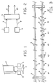
- FIG. 1 shows a typical arrangement of a wheel sensor with two associated inductive sensors (1, 3) known per se.
- the sensors (1, 3) are arranged symmetrically to a travel rail (4) in the track (2).
- a wheel (6) rolling over the travel rail (4) influences the sensors (1, 3) differently due to its asymmetry.
- the sensor (3) facing the wheel rim is influenced more because of the relatively closer, larger mass of the wheel (6), so that there is a more influenced level (9) at the output of this sensor (3).
- a wheel with a wheel flange can be clearly identified despite all interfering influences that act symmetrically or almost symmetrically on the sensors (1, 3).
- These interferences can be eliminated by comparing the levels (7, 9) of the sensors (1, 3).
- such interferences can be electrical, inductive, thermal or mechanical, among other things.
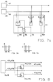
- a typical evaluation circuit of a wheel sensor is shown in FIG.
- the levels (7, 9) of two assigned inductive sensors (1, 3) are routed to a comparator (5), which emits a wheel-recognizing level (11) at the output if the levels are not the same.
- the wheel-recognizing output level (11) can be suppressed in the comparator (5) and / or a further output level (13) indicating an error. are given by the comparator (5).
- variable levels (7, 9) of the sensors (1, 3) known per se can e.g. rectified or non-rectified voltages or currents based on changes in the influence of their inductance, inductance coupling, resonant circuit damping, phase or frequency by a wheel (6) of a rail vehicle.
- Fig. 3 shows different arrangements of typical wheel sensors in the track (2).
- the assigned sensors (1, 3) can e.g. B. consist of a damped by a wheel (6) resonant circuit or a transmitting and receiving coil, the coupling of which is influenced by a wheel (6).
- the transmission and reception coils of a sensor (1, 3) are arranged horizontally apart from one another, the transmission coils are shown as a triangle and the reception coils as a square in FIG. 3.
- the coils can be, for example, concentrated air coils, a ferrite core contain or be designed as larger frame coils.
- the 3a corresponds to the top view of the inductive sensors (1, 3) of a wheel sensor according to FIG. 3.
- the sensors (1, 3) can contain only one coil or vertically arranged transmitting and receiving coils.
- Fig. 3b sensors (1, 3) of a wheel sensor are attached to both rails (4) in the same transverse direction. Since the wheel flanges of the wheels (6) of one axle face each other, the same effect results as in the arrangement according to FIG. 3a.
- 3c shows a wheel sensor with horizontally offset transmission and reception coils of sensors 1 and 3.
- FIG. 3d shows a further arrangement of a wheel sensor with sensors (1, 3) having several coils.
- the wheel sensor according to FIG. 3e consists of two sensors (1, 3) arranged along a track, the level (23) of the sensor first traveled being delayed until the other sensor is used for the purpose of comparison (5).
- the direction of travel can be recognized by the sensors traveled in succession and their output levels which are thereby offset in time, and if the zones of influence and the resulting level overlap, a reversal of direction after a standstill .
- FIG. 3g For an arrangement according to FIG. 3g, only two sensors (1, 3), but a level delay as mentioned in FIG. 3e are necessary for the purpose of comparison.
- FIG. 4 shows a circuit principle for comparison of sensors (1, 3) of a wheel sensor arranged along the travel rail (4).
- the levels (7, 9) of the sensors (1, 3) are fed to a switch (15) which detects the change in level of the sensor first traveled and transfers this level (23) to a memory (19) which stores the level or level curve with a delay and then only outputs to the comparator (5) when the switch (15) detects the change in level when the other sensor is driven, the level (21) of which supplies the switch (15) to the comparator (5) directly or via an adapter circuit (17) so that this level and the level delayed by the memory can be compared as if the sensors (1, 3) had been run over at the same time.
- the memory (19) can, for example, be based on the known, not known, basis of a sample / hold circuit, a bucket chain circuit, a signal processor or analog / digital converter with a serial FIFO memory connected downstream.
- a matching circuit (17) for example an analog / digital converter, is necessary in order to achieve the same type of level at the input of the comparator (5).
- the filters (25, 27, 29) can reduce interference and suppress runtime differences.
- the filter 29 after the level comparison essentially serves to suppress runtime differences.
- Threshold switches (31, 33, 35) suppress levels that are too low in order to eliminate only small deviations or changes in the levels. By responding to levels that are too high and suppressing them, excessive influences can be eliminated with the threshold switches (31, 33, 35); the influences of a very strongly excited eddy current brake can e.g. B. combat in addition to the symmetrical suppression properties of the wheel sensor.
- the comparator (5) can also compare the input levels (7, 9) in a manner known per se, not shown in detail, on the basis of the formation of the quotient and / or difference, the unwanted dependence on absolute levels being better suppressed.
- FIG. 6 shows a typical evaluation circuit of a wheel sensor which contains a logic circuit (61).
- the sensor pair (43) when the level of the sensor facing the wheel flange is predominant, gives the sensor pair (41, 43) a wheel signal (51) corresponding to the passing of a proper wheel, a detection signal (55) at approximately the same level of both sensor pairs (41, 43) corresponding to a metallic object passing symmetrically to the rail head and at a predominant level of the one facing away from the wheel flange Sensor (41) an error signal (53).
- the levels (47, 49) in Fig. 7b are approximately the same size according to a symmetrical, metallic object above the sensor pair (41, 43), which leads to the detection signal (55) at the output of the associated AND gate in Fig. 7a, when the switching threshold S in Fig. 7b is exceeded by both levels.
- the levels (47, 49) shown by way of example in FIG. 7c differ in size according to a correct wheel above the sensor pair (41, 43), which leads to the wheel signal (51) at the output of the associated AND gate in FIG. 7a if the switching threshold S in FIG. 7c falls below the level 47 and is exceeded by the level 49 and the levels are lowered with the same resistances R to such an extent that the level 47 is below the switching threshold in the fault-free case shown.
- the error signal (53) is expediently used to reject the entire measuring process of the wheel sensor.
- the temporal sequence (56) of the wheel signals (51) or the detection signals (55) is obtained from the latter signals by an OR gate (FIG. 7a).
- the logic circuit (61) is better constructed from analog elements already mentioned at the beginning for better interference suppression.
- FIG. 9 shows an example of a current data pattern, this occurs when the wheel signal (51) is clocked out as a 1-bit sequence with the temporal sequence signal (56).
- the wheels are recorded as binary ones and the symmetrical metal objects as binary zeros.
- the data pattern can be seen in the example 3 wheels 1 symmetrical metal object 2 wheels 1 symmetrical metal object n wheels
- Train types can thus be set as data patterns on the train and recorded with the sensor pairs (41, 43), primarily from the first bit sequences, which are assigned to the train's drive unit, for example. If there is insufficient identification due to the consequence of wheel and eddy current brakes and / or magnetic rail brakes, coding plates on the train can also be used.
- the number of binary ones in the example corresponds to the number of axles of the train and can be easily separated for evaluation.
- FIG. 6 shows how the mentioned signals or current data patterns (FIG. 9) are fed to a computer (63) in the evaluation circuit (45).
- the computer (63) has a memory (not shown) and a program and is connected to a timer (57).
- the computer can recognize the train type and its possible speed and acceleration by comparing the current data pattern (FIG. 9) detected by the sensor pairs and the evaluation circuit. From these variables, the computer can determine the period of time in which the train covers, for example, an average or at the earliest a certain distance, using known calculation methods. If the calculation is based on the maximum possible speed, the earliest arrival of the train at a location with a known distance from the wheel sensor can be predetermined. Data or messages about this can be output (65) or via a data transmission (67) at their output (69).
- the data or messages are transmitted via the data transmission (67), for example, to a location of a construction site in the track area on which the calculation is based and evaluated there, a time-delayed, but nevertheless timely warning resulting from the calculation can be triggered there. Construction work does not have to be interrupted prematurely.
- a computer (not described in more detail) with equivalent properties such as the computer 63 together with a data transmission similar to the data transmission 67 can be used for the evaluation.
- the computer (63) can, however, also measure the temporal sequence of at least the first wheel or detection signals (51, 55) and stored data associated with the train type about the absolute distances of at least the first wheel axles and / or metallic passing by symmetrically to the rail head Objects to determine the current speed of the train. With this current speed and the maximum possible acceleration, the arrival of the train at locations relative to the wheel sensor can be determined more precisely according to known calculation methods.
- the computer (63) can determine the levels (47a, 47b or 49a, 49b) of the coils of the sensor pairs (41, 43) also easier to determine the current speed of the train.
- FIG. 8 shows a D flip-flop circuit (41a, 41b, or 43a, 43b), which is contained in the evaluation circuit (45) and with which the direction of pull can be detected.
- a D flip-flop circuit 41a, 41b, or 43a, 43b
- the designations 41a, 41b, 47a, 47b, 47c and 47c are assigned to the sensor 41, the rest to the sensor 43.
- the mode of operation is identical for both sensors.
- the inductively influenced coils of the sensor pairs (41, 43) arranged along the track in succession are given correspondingly successive levels (47a, 47b, or 49a, 49b) from the inputs of the D flip-flop circuit (41a, 41b, or 43a, 43b). For example, if the level 47a at the data input of the D flip-flop 41a occurs before the level 47b at its clock input, the former level is passed to the output of the D flip-flop 41a as a direction signal 49c when the level 47b arrives. The D flip-flop 41b, however, does not pass a level to its output. With the reverse order of the levels, the D flip-flops behave in reverse.
- the outputs (47c, 47d or 49c, 49d) differ according to the order of the levels and indicate the direction of travel of the train. After detection of the direction signals, the D flip-flops are reactivated by resetting, which is not shown in FIG. 8 because of the clarity.
- the information about the direction of the train can be used, for example, in connection with the notification of the arrival of the train at certain locations or for direction-dependent axle counting.
- the computer (63) in FIG. 6 can also contain analog / digital converters (not shown), expediently one for each signal-emitting coil of the sensor pair (41, 43). If the levels (47, 49) of the sensor pairs (41, 43) are converted into digital values so quickly that at least 3 values are stored when a sensor and a wheel and / or a metallic object are affected, then an increasing number of values per Influencing a better and better resolved equivalent recognition pattern of the measured object in the form of a table of values. In contrast to angular brakes, a wheel is characterized, for example, by small increments in the associated table of values because of its round shape. The significance of the measured objects can be determined by known calculation methods using comparison tables permanently stored in the computer (63). In a logical connection with wheel signals (51), or detection signals (55), or error signals (53), the safety of the wheel sensor can be increased to a level required for signal safety in modern railway operations.
- the signals 51, 53, 55, 56 of the evaluation circuit (45) in FIG. 6 and / or the current data pattern (FIG. 9) or the like can also be transmitted to a remote location via the data transmission 67 and processed there in a similar or identical manner are in the computer 63.
- the data can be compressed, for example the current data pattern in the example of FIG as a sequence of digits 3, 1, 2, 1, n instead of the bit sequence.
- the pair of sensors (41, 43) can each contain a first transmitter and / or receiver (71). If the trains themselves each contain a second transmitter and / or receiver (73) directly above the rail, data can be exchanged wirelessly between the transmitters and / or receivers (71, 73) in a manner known per se, the computer (63) corresponds to the first transmitter and / or receiver (71) via a data line (65) and the train corresponds to the second transmitter and / or receiver (73) via line 75.
- the first transmitter and / or receiver (71) can also be part or all of the coils of the sensor pair (41, 43) on an inductive basis, in particular if the coils are used in a generally known compensating manner to prevent the mutual influence of the transmission of the data and the measurements Bridge circuit are arranged.
- Signal security can be achieved if the evaluation circuit (45), possibly also the data transmission (67) and / or the transmitter / receiver (71, 73) and the corresponding connections (47, 49, 65, 69, 75) as a second decoupled functional unit are present again, the functional units work in the same way and monitor each other for the same and simultaneous output signals.
Landscapes
- Engineering & Computer Science (AREA)
- Automation & Control Theory (AREA)
- Mechanical Engineering (AREA)
- Physics & Mathematics (AREA)
- Electromagnetism (AREA)
- Train Traffic Observation, Control, And Security (AREA)
- Electric Propulsion And Braking For Vehicles (AREA)
- Chain Conveyers (AREA)
- Measurement Of Length, Angles, Or The Like Using Electric Or Magnetic Means (AREA)
Applications Claiming Priority (4)
| Application Number | Priority Date | Filing Date | Title |
|---|---|---|---|
| DE4129138 | 1991-09-02 | ||
| DE19914129138 DE4129138C1 (en) | 1991-09-02 | 1991-09-02 | Rail vehicle wheel sensor system - uses metal detecting inductive sensors arranged symmetrically on rail and suppresses interference to enable differentiation between flanged and flangeless wheels |
| DE4229131 | 1992-09-01 | ||
| DE19924229131 DE4229131C1 (fr) | 1992-09-01 | 1992-09-01 |
Publications (3)
| Publication Number | Publication Date |
|---|---|
| EP0530743A2 true EP0530743A2 (fr) | 1993-03-10 |
| EP0530743A3 EP0530743A3 (en) | 1993-05-12 |
| EP0530743B1 EP0530743B1 (fr) | 1995-01-11 |
Family
ID=25906922
Family Applications (1)
| Application Number | Title | Priority Date | Filing Date |
|---|---|---|---|
| EP92114914A Expired - Lifetime EP0530743B1 (fr) | 1991-09-02 | 1992-09-01 | Dispositif de détection de roues de véhicules ferroviaires |
Country Status (4)
| Country | Link |
|---|---|
| EP (1) | EP0530743B1 (fr) |
| AT (1) | ATE116919T1 (fr) |
| DE (1) | DE59201186D1 (fr) |
| ES (1) | ES2069947T3 (fr) |
Cited By (8)
| Publication number | Priority date | Publication date | Assignee | Title |
|---|---|---|---|---|
| EP2305533A3 (fr) * | 2004-07-16 | 2012-04-18 | Lynxrail Corporation | Appareil pour détecter le lacet et l'angle d'attaque d'un essieu de véhicule ferroviaire |
| EP3296181A3 (fr) * | 2016-09-19 | 2018-08-08 | voestalpine SIGNALING Sopot Sp. z o.o. | Procédé et système de syntonisation de capteur inductif pour la détection de la présence de roues de véhicules ferroviaires |
| CN114670893A (zh) * | 2022-04-26 | 2022-06-28 | 南京拓控信息科技股份有限公司 | 一种车轮掉块的检测方法 |
| EP4155162A1 (fr) * | 2021-09-22 | 2023-03-29 | Siemens Mobility GmbH | Procédé et dispositif pourvu de compteur d'essieux permettant de faire fonctionner un passage à niveau |
| CN117184168A (zh) * | 2023-03-29 | 2023-12-08 | 黑龙江瑞兴科技股份有限公司 | 一种轮缘式计轴轨道电路系统 |
| CN117208034A (zh) * | 2023-10-07 | 2023-12-12 | 温州市铁路与轨道交通投资集团有限公司 | 二取二架构计轴设备数据处理方法、装置及计轴设备 |
| WO2024068313A1 (fr) * | 2022-09-29 | 2024-04-04 | Siemens Mobility GmbH | Procédé et système de surveillance d'une partie de voie |
| EP4383097A1 (fr) * | 2022-12-08 | 2024-06-12 | Siemens Mobility GmbH | Validation d'une série temporelle binaire simulée |
Family Cites Families (4)
| Publication number | Priority date | Publication date | Assignee | Title |
|---|---|---|---|---|
| DE764957C (de) * | 1942-08-18 | 1953-06-08 | Ver Eisenbahn Signalwerke G M | Einrichtung zur Zeichenuebertragung von Eisenbahnzuegen auf die Strecke durch induktive Einwirkung der Raeder auf an der Strecke angeordnete Eisenkerne |
| DE958848C (de) * | 1953-10-13 | 1957-02-28 | Siemens Ag | Anordnung bei Eisenbahnen zur UEbertragung von Zeichen vom Zuge auf die Strecke |
| US2892078A (en) * | 1957-03-14 | 1959-06-23 | Itt | Detecting apparatus |
| FR2617315A1 (fr) * | 1987-06-23 | 1988-12-30 | Sfim | Procede et dispositif de discrimination du type d'un vehicule automobile en circulation |
-
1992
- 1992-09-01 DE DE59201186T patent/DE59201186D1/de not_active Expired - Fee Related
- 1992-09-01 EP EP92114914A patent/EP0530743B1/fr not_active Expired - Lifetime
- 1992-09-01 ES ES92114914T patent/ES2069947T3/es not_active Expired - Lifetime
- 1992-09-01 AT AT92114914T patent/ATE116919T1/de not_active IP Right Cessation
Cited By (10)
| Publication number | Priority date | Publication date | Assignee | Title |
|---|---|---|---|---|
| EP2305533A3 (fr) * | 2004-07-16 | 2012-04-18 | Lynxrail Corporation | Appareil pour détecter le lacet et l'angle d'attaque d'un essieu de véhicule ferroviaire |
| EP3296181A3 (fr) * | 2016-09-19 | 2018-08-08 | voestalpine SIGNALING Sopot Sp. z o.o. | Procédé et système de syntonisation de capteur inductif pour la détection de la présence de roues de véhicules ferroviaires |
| EP4155162A1 (fr) * | 2021-09-22 | 2023-03-29 | Siemens Mobility GmbH | Procédé et dispositif pourvu de compteur d'essieux permettant de faire fonctionner un passage à niveau |
| US12454296B2 (en) | 2021-09-22 | 2025-10-28 | Siemens Mobility GmbH | Method and apparatus with an axle counter for operating a railroad crossing, computer program product and delivery apparatus for the computer program product |
| CN114670893A (zh) * | 2022-04-26 | 2022-06-28 | 南京拓控信息科技股份有限公司 | 一种车轮掉块的检测方法 |
| CN114670893B (zh) * | 2022-04-26 | 2024-04-30 | 南京拓控信息科技股份有限公司 | 一种车轮掉块的检测方法 |
| WO2024068313A1 (fr) * | 2022-09-29 | 2024-04-04 | Siemens Mobility GmbH | Procédé et système de surveillance d'une partie de voie |
| EP4383097A1 (fr) * | 2022-12-08 | 2024-06-12 | Siemens Mobility GmbH | Validation d'une série temporelle binaire simulée |
| CN117184168A (zh) * | 2023-03-29 | 2023-12-08 | 黑龙江瑞兴科技股份有限公司 | 一种轮缘式计轴轨道电路系统 |
| CN117208034A (zh) * | 2023-10-07 | 2023-12-12 | 温州市铁路与轨道交通投资集团有限公司 | 二取二架构计轴设备数据处理方法、装置及计轴设备 |
Also Published As
| Publication number | Publication date |
|---|---|
| EP0530743B1 (fr) | 1995-01-11 |
| ES2069947T3 (es) | 1995-05-16 |
| EP0530743A3 (en) | 1993-05-12 |
| DE59201186D1 (de) | 1995-02-23 |
| ATE116919T1 (de) | 1995-01-15 |
Similar Documents
| Publication | Publication Date | Title |
|---|---|---|
| DE3431171C2 (de) | Gleisfreimeldeeinrichtung mit Achszählung | |
| EP2718168A1 (fr) | Procédé d'exploitation d'un équipement de sécurité ferroviaire et équipement de sécurité ferroviaire | |
| WO2012004251A1 (fr) | Dispositif de détection inductif et détecteur de proximité inductif comportant un dispositif de détection inductif | |
| EP3374246B1 (fr) | Procédé et dispositif de détection de déraillement commandée par comparaison | |
| EP0530743B1 (fr) | Dispositif de détection de roues de véhicules ferroviaires | |
| DE2124089A1 (de) | Einrichtung bei Schienenbahnen zur Informationsübertragung von der Strecke auf die Fahrzeuge | |
| EP3938265B1 (fr) | Procédé servant à définir l'occupation d'une voie, ainsi que dispositif compteur d'essieux | |
| EP2146886A1 (fr) | Capteur de roue | |
| EP3976439B1 (fr) | Dispositif de capteur pour un ensemble de détection et d'analyse d'une roue d'un véhicule déplacée le long d'une voie, en particulier le long d'une voie ferrée | |
| DE4129138C1 (en) | Rail vehicle wheel sensor system - uses metal detecting inductive sensors arranged symmetrically on rail and suppresses interference to enable differentiation between flanged and flangeless wheels | |
| DE4229131C1 (fr) | ||
| EP0396798B1 (fr) | Procédé et dispositif de détection de véhicules ferroviaires | |
| DE3236367A1 (de) | Einrichtung zur gleisfreimeldung, zugortung und geschwindigkeitsmessung | |
| EP4417484A1 (fr) | Système de compteur d'essieux pour surveiller une section de voie d'un système de rails | |
| EP1101684B1 (fr) | Procédé de signalisation de voie libre au moyen d'un compteur d'essieux | |
| DE3118421C2 (fr) | ||
| DE2652233B2 (de) | Einrichtung zur selbsttätigen Korrektur von Zählfehlern in Achszähleinrichtungen | |
| DE2617943B2 (de) | Einrichtung fuer beruehrungslose weg- und geschwindigkeitsmessungen bei spurgebundenen fahrzeugen | |
| DE3201293A1 (de) | Einrichtung zur ueberwachung des frei- oder besetztzustandes eines gleisabschnittes | |
| EP4144612A1 (fr) | Dispositif capteur, agencement et procédé de détection d'un changement d'un champ magnétique | |
| DE4444517A1 (de) | Einrichtung zum Synchronisieren eines fahrzeugseitigen Wegzählers | |
| DE19817636C2 (de) | Elektrisch ortsbediente Weiche | |
| DE3047119C2 (de) | Anordnung zur Ermittlung der Fahrtrichtung schienengebundener Fahrzeuge | |
| DE4436011B4 (de) | System zur Steuerung von spurgebundenen Fahrzeugen mit verbesserter Fahrzeugortung | |
| DE19627343A1 (de) | Einrichtung zur Eigenortung eines spurgeführten Fahrzeugs |
Legal Events
| Date | Code | Title | Description |
|---|---|---|---|
| PUAI | Public reference made under article 153(3) epc to a published international application that has entered the european phase |
Free format text: ORIGINAL CODE: 0009012 |
|
| AK | Designated contracting states |
Kind code of ref document: A2 Designated state(s): AT BE CH DE DK ES FR GB GR IT LI NL PT SE |
|
| PUAL | Search report despatched |
Free format text: ORIGINAL CODE: 0009013 |
|
| AK | Designated contracting states |
Kind code of ref document: A3 Designated state(s): AT BE CH DE DK ES FR GB GR IT LI NL PT SE |
|
| 17P | Request for examination filed |
Effective date: 19930921 |
|
| 17Q | First examination report despatched |
Effective date: 19940208 |
|
| GRAA | (expected) grant |
Free format text: ORIGINAL CODE: 0009210 |
|
| AK | Designated contracting states |
Kind code of ref document: B1 Designated state(s): AT BE CH DE DK ES FR GB GR IT LI NL PT SE |
|
| PG25 | Lapsed in a contracting state [announced via postgrant information from national office to epo] |
Ref country code: NL Effective date: 19950111 Ref country code: GR Free format text: LAPSE BECAUSE OF FAILURE TO SUBMIT A TRANSLATION OF THE DESCRIPTION OR TO PAY THE FEE WITHIN THE PRESCRIBED TIME-LIMIT Effective date: 19950111 Ref country code: DK Effective date: 19950111 Ref country code: BE Effective date: 19950111 |
|
| REF | Corresponds to: |
Ref document number: 116919 Country of ref document: AT Date of ref document: 19950115 Kind code of ref document: T |
|
| REF | Corresponds to: |
Ref document number: 59201186 Country of ref document: DE Date of ref document: 19950223 |
|
| ITF | It: translation for a ep patent filed | ||
| GBT | Gb: translation of ep patent filed (gb section 77(6)(a)/1977) |
Effective date: 19950307 |
|
| PG25 | Lapsed in a contracting state [announced via postgrant information from national office to epo] |
Ref country code: PT Effective date: 19950411 |
|
| ET | Fr: translation filed | ||
| REG | Reference to a national code |
Ref country code: ES Ref legal event code: FG2A Ref document number: 2069947 Country of ref document: ES Kind code of ref document: T3 |
|
| NLV1 | Nl: lapsed or annulled due to failure to fulfill the requirements of art. 29p and 29m of the patents act | ||
| PG25 | Lapsed in a contracting state [announced via postgrant information from national office to epo] |
Ref country code: AT Effective date: 19950901 |
|
| PLBE | No opposition filed within time limit |
Free format text: ORIGINAL CODE: 0009261 |
|
| 26N | No opposition filed | ||
| REG | Reference to a national code |
Ref country code: FR Ref legal event code: TP |
|
| REG | Reference to a national code |
Ref country code: CH Ref legal event code: PUE Owner name: STEIN GMBH TRANSFER- HERMANN STEIN |
|
| REG | Reference to a national code |
Ref country code: CH Ref legal event code: PUE Owner name: HERMANN STEIN TRANSFER- SCHWEIZER ELECTRONIC M2S A Ref country code: CH Ref legal event code: NV Representative=s name: BOVARD AG PATENTANWAELTE |
|
| REG | Reference to a national code |
Ref country code: GB Ref legal event code: IF02 |
|
| REG | Reference to a national code |
Ref country code: GB Ref legal event code: 732E |
|
| REG | Reference to a national code |
Ref country code: ES Ref legal event code: PC2A |
|
| REG | Reference to a national code |
Ref country code: FR Ref legal event code: TP |
|
| PGFP | Annual fee paid to national office [announced via postgrant information from national office to epo] |
Ref country code: FR Payment date: 20030811 Year of fee payment: 12 |
|
| PGFP | Annual fee paid to national office [announced via postgrant information from national office to epo] |
Ref country code: GB Payment date: 20030815 Year of fee payment: 12 |
|
| PGFP | Annual fee paid to national office [announced via postgrant information from national office to epo] |
Ref country code: SE Payment date: 20030819 Year of fee payment: 12 |
|
| PGFP | Annual fee paid to national office [announced via postgrant information from national office to epo] |
Ref country code: DE Payment date: 20030821 Year of fee payment: 12 |
|
| PGFP | Annual fee paid to national office [announced via postgrant information from national office to epo] |
Ref country code: ES Payment date: 20030908 Year of fee payment: 12 |
|
| PGFP | Annual fee paid to national office [announced via postgrant information from national office to epo] |
Ref country code: CH Payment date: 20030910 Year of fee payment: 12 |
|
| PG25 | Lapsed in a contracting state [announced via postgrant information from national office to epo] |
Ref country code: GB Free format text: LAPSE BECAUSE OF NON-PAYMENT OF DUE FEES Effective date: 20040901 |
|
| PG25 | Lapsed in a contracting state [announced via postgrant information from national office to epo] |
Ref country code: SE Free format text: LAPSE BECAUSE OF NON-PAYMENT OF DUE FEES Effective date: 20040902 Ref country code: ES Free format text: LAPSE BECAUSE OF NON-PAYMENT OF DUE FEES Effective date: 20040902 |
|
| PG25 | Lapsed in a contracting state [announced via postgrant information from national office to epo] |
Ref country code: LI Free format text: LAPSE BECAUSE OF NON-PAYMENT OF DUE FEES Effective date: 20040930 Ref country code: CH Free format text: LAPSE BECAUSE OF NON-PAYMENT OF DUE FEES Effective date: 20040930 |
|
| PG25 | Lapsed in a contracting state [announced via postgrant information from national office to epo] |
Ref country code: DE Free format text: LAPSE BECAUSE OF NON-PAYMENT OF DUE FEES Effective date: 20050401 |
|
| GBPC | Gb: european patent ceased through non-payment of renewal fee |
Effective date: 20040901 |
|
| EUG | Se: european patent has lapsed | ||
| REG | Reference to a national code |
Ref country code: CH Ref legal event code: PL |
|
| PG25 | Lapsed in a contracting state [announced via postgrant information from national office to epo] |
Ref country code: FR Free format text: LAPSE BECAUSE OF NON-PAYMENT OF DUE FEES Effective date: 20050531 |
|
| REG | Reference to a national code |
Ref country code: FR Ref legal event code: ST |
|
| PG25 | Lapsed in a contracting state [announced via postgrant information from national office to epo] |
Ref country code: IT Free format text: LAPSE BECAUSE OF NON-PAYMENT OF DUE FEES;WARNING: LAPSES OF ITALIAN PATENTS WITH EFFECTIVE DATE BEFORE 2007 MAY HAVE OCCURRED AT ANY TIME BEFORE 2007. THE CORRECT EFFECTIVE DATE MAY BE DIFFERENT FROM THE ONE RECORDED. Effective date: 20050901 |
|
| REG | Reference to a national code |
Ref country code: ES Ref legal event code: FD2A Effective date: 20040902 |