EP0530841A1 - Véhicule - Google Patents
Véhicule Download PDFInfo
- Publication number
- EP0530841A1 EP0530841A1 EP92115285A EP92115285A EP0530841A1 EP 0530841 A1 EP0530841 A1 EP 0530841A1 EP 92115285 A EP92115285 A EP 92115285A EP 92115285 A EP92115285 A EP 92115285A EP 0530841 A1 EP0530841 A1 EP 0530841A1
- Authority
- EP
- European Patent Office
- Prior art keywords
- base frame
- vehicle according
- frame
- wheel
- steering wheel
- Prior art date
- Legal status (The legal status is an assumption and is not a legal conclusion. Google has not performed a legal analysis and makes no representation as to the accuracy of the status listed.)
- Granted
Links
Images

Classifications
-
- A—HUMAN NECESSITIES
- A01—AGRICULTURE; FORESTRY; ANIMAL HUSBANDRY; HUNTING; TRAPPING; FISHING
- A01D—HARVESTING; MOWING
- A01D46/00—Picking of fruits, vegetables, hops, or the like; Devices for shaking trees or shrubs
- A01D46/24—Devices for picking apples or like fruit
- A01D46/243—Accessories specially adapted for manual picking, e.g. ladders, carts
Definitions
- the invention relates to a vehicle for Tramsport of loads, for example in fruit and vegetable growing or in the municipal sector, with a base frame for receiving the loads, two axles and a drive unit and a steering wheel.
- Such vehicles are available as small load vehicles in a variety of forms on the market and known.
- loaded trailers are pulled by single-axle, two-axle or small tugs. But especially in unclear terrain or in fruit and vegetable crops, the lack of clarity when driving with such vehicles has a very negative effect.
- the inventor has set himself the goal of a vehicle of the above. To develop kind, which is small, handy and very good maneuverable.
- the steering wheel is arranged in the direction of travel behind the base frame.
- This design means that the driver of this vehicle, for example, in fruit and vegetable crops much easier to control and can handle curves much better.
- the vehicle can also rotate around itself. Since the driver also has the basic frame for the load suspension in front of him, he is given a better and clearer driving on the hand.
- the driver should preferably not sit in this vehicle, but stand on a standing plate behind the wheel. This speeds up the ascent and descent.
- the driver can turn better on the standing plate and align to the rear. This is especially important if the vehicle carries a large number of other trailers. For this purpose, a trailer hitch is otherwise provided on the standing plate.
- the standing plate is connected to the base frame or with an upstanding from the base frame end frame via a wheel well.
- a wheel axle which may be, for example, the driven wheel axle.
- the wheel housing and the drive unit sits on and is connected via corresponding transmission elements with the wheel axle.
- this wheel axle is rotatably arranged or is designed as a steering axle.
- the steering can also take place by means of a corresponding rotary shaft on a further wheel.
- This frame is then in turn connected to the basic frame.
- connection between the steering wheel and the rotatable wheel axle There are many possibilities for the connection between the steering wheel and the rotatable wheel axle. The simplest is the one about corresponding gears and drive belts. Therefore, it is preferred in the present invention.
- the frame, on which the steerable wheel axle hangs, can additionally also be designed as a footprint for boxes or the like. So that they do not slip, the frame is provided with a circumferential side strip. This also makes it easier to fill these boxes, as picking staff, for example, does not have to go down to the box. Therefore, the frame should be higher than the base frame, which serves according to the invention to carry larger boxes.
- the base frame is height adjustable. This can be done by mechanical or hydraulic axle swing or by supports against the axes. This embodiment is desirable especially in crops.
- the base frame laterally tiltable. This is particularly advantageous when filling larger boxes, since on the one hand, the filling itself is facilitated and on the other hand, the degree of filling of the box can be increased.
- the base frame should be tiltable about a central tube, this central tube extends in the direction of travel.
- this central tube extends in the direction of travel.
- tube sections engage in the central tube, so that this central tube rotates when tilted in relation to the tube sections.
- the determination of the base frame in a certain tilted position serves for simplicity, a firmly connected to the base frame tab, which rises and abuts a fixedly connected to the end frame plate.
- the tab in this case has a bore which coincides in a certain tilted position with corresponding holes in the plate. Through these holes then a corresponding locking bolt is used.
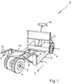
- a vehicle P according to the invention which is preferably to be used in fruit and vegetable cultivation, has gene.
- Fig. 1 a base frame 1, which is arranged between two wheel axles 2 and 3 with corresponding wheels 4.
- the base frame 1 consists of a middle, lower-lying support frame 5, from each of which front and rear an end frame 6 and 7 rises.
- the base frame 1 together with the end frame 6 and 7 designed so that it can be placed on him between the two end frames 6 and 7, a corresponding, standardized transport box. Since there are no side frames, this transport box can be used in a simple manner from the side, for example, with a corresponding forklift.
- end frame 6 is formed in the present embodiment with a much lower height than the front frame 7. From an upper rail 8 of the end frame 6 projects from another frame 9, od in the operating position of the vehicle P, for example, a fruit box od. like. be set up can. So that this does not slip when driving the vehicle P, the frame 9 circulate side stripes 10.
- the frame 9 overlaps the rest of the wheel axle 2 with the wheels 4 and is supported to increase its carrying capacity via support struts 11 against the base frame 1.
- the wheel axle 2 is otherwise formed as a rotation axis A, so that it determines the cornering of the vehicle P.
- a rotary shaft 12 projects upwards from the wheel axle 2 and is fixed to the frame 9 or a middle plate 13, wherein the rotary shaft 12 can rotate about the axis of rotation A.
- the rotation of the rotary shaft 12 about the axis of rotation A is effected by means of a steering wheel 14, which is located behind the end frame 7.
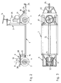
- a drive belt 15, for example, a chain are moved, which is in communication with a gear 16 below the frame 9.
- From the gear 16 the transmission of the steering movement via an intermediate shaft 17 to another gear 18, which is rotatably mounted on the underside of the middle plate 13.
- This gear 18 is in turn connected via a drive belt 19 with a gear 20 in connection, which is the rotary shaft 12 rotatably mounted.
- the wheel axle 2 is located after the end frame 7, the wheel axle 3, also with wheels 4.
- These wheels 4 are at least partially covered by a wheel arch 21, projects from the back of a standing plate 22.
- An operator can step on this standing plate 22 and operate corresponding clutch lever 23 or a brake lever 24.
- To the rear of this standing plate 22 is still a trailer hitch 25 for attaching to be pulled with the vehicle P towing wagons for fruits and vegetables.
- drive unit 26 for example, a commercial gasoline engine.
- the wheel axle 3 is driven via a gear not shown in detail.
- FIG. 4 shows that the base frame 1a can also be tilted laterally in the direction x.
- the base frame 1 a detached from the end frame 6 and 7 and is connected to this articulated via a central tube 28 which is pushed over corresponding protruding from the end frame 6 and 7 pipe sections 29.
- On the central tube 28 of the base frame 1 a sits, so that the central tube 28 rotates with a tilting of the base frame 1 a relative to the pipe section 29.
- the fixing of the base frame 1a in a certain position is for simplicity a bolt 31, which passes through a hole in a tab 32 on the base frame 1a and on the other hand can engage in holes 33 in a plate 34 on the end frame 6. It goes without saying that a corresponding plate 34 with holes 33 is also on the end frame 7, which also cooperates by means of a bolt with a corresponding tab on the base frame 1a.
Landscapes
- Life Sciences & Earth Sciences (AREA)
- Environmental Sciences (AREA)
- Handcart (AREA)
- Agricultural Machines (AREA)
- Pharmaceuticals Containing Other Organic And Inorganic Compounds (AREA)
- Centrifugal Separators (AREA)
- Seal Device For Vehicle (AREA)
Applications Claiming Priority (2)
| Application Number | Priority Date | Filing Date | Title |
|---|---|---|---|
| DE9111061U | 1991-09-06 | ||
| DE9111061U DE9111061U1 (de) | 1991-09-06 | 1991-09-06 | Fahrzeug |
Publications (2)
| Publication Number | Publication Date |
|---|---|
| EP0530841A1 true EP0530841A1 (fr) | 1993-03-10 |
| EP0530841B1 EP0530841B1 (fr) | 1998-04-15 |
Family
ID=6870987
Family Applications (1)
| Application Number | Title | Priority Date | Filing Date |
|---|---|---|---|
| EP92115285A Expired - Lifetime EP0530841B1 (fr) | 1991-09-06 | 1992-09-07 | Véhicule |
Country Status (3)
| Country | Link |
|---|---|
| EP (1) | EP0530841B1 (fr) |
| AT (1) | ATE165058T1 (fr) |
| DE (2) | DE9111061U1 (fr) |
Cited By (2)
| Publication number | Priority date | Publication date | Assignee | Title |
|---|---|---|---|---|
| BE1007486A3 (nl) * | 1993-09-10 | 1995-07-11 | Jammaers Rene | Inrichting om te worden aangewend bij het plukken van vruchten. |
| CN108082308A (zh) * | 2017-12-18 | 2018-05-29 | 聊城大学 | 一种带有减震机构的载货平板车 |
Families Citing this family (1)
| Publication number | Priority date | Publication date | Assignee | Title |
|---|---|---|---|---|
| DE9209036U1 (de) * | 1992-07-06 | 1992-09-10 | Weco Industrietechnik GmbH, 34127 Kassel | Spurgeführtes Transportsystem |
Citations (7)
| Publication number | Priority date | Publication date | Assignee | Title |
|---|---|---|---|---|
| DE1753087U (de) * | 1957-07-01 | 1957-09-26 | Nikolaus Siemer | Kippvorrichtung fuer gummibereifte gespannwagen. |
| DE1836913U (de) * | 1961-04-27 | 1961-08-31 | Orenstein & Koppel Ag | Autoschuetter. |
| DE1859922U (de) * | 1962-07-27 | 1962-10-11 | Wilhelm Scheidt K G Maschinenf | Muldenkipper, insbesondere als kraftfahrzeug aufgebauter muldenkipper. |
| FR1357729A (fr) * | 1963-02-26 | 1964-04-10 | Remorque perfectionnée | |
| DE1923341A1 (de) * | 1968-05-07 | 1969-11-20 | Triplett James Thomas | Elektrofahrzeug |
| DE1555691A1 (de) * | 1965-02-11 | 1970-06-04 | Hausner Martin | Transportfahrzeug |
| FR2307692A1 (fr) * | 1975-04-15 | 1976-11-12 | Guerbet Francois | Systeme de direction de vehicule |
-
1991
- 1991-09-06 DE DE9111061U patent/DE9111061U1/de not_active Expired - Lifetime
-
1992
- 1992-09-07 EP EP92115285A patent/EP0530841B1/fr not_active Expired - Lifetime
- 1992-09-07 DE DE59209282T patent/DE59209282D1/de not_active Expired - Fee Related
- 1992-09-07 AT AT92115285T patent/ATE165058T1/de not_active IP Right Cessation
Patent Citations (7)
| Publication number | Priority date | Publication date | Assignee | Title |
|---|---|---|---|---|
| DE1753087U (de) * | 1957-07-01 | 1957-09-26 | Nikolaus Siemer | Kippvorrichtung fuer gummibereifte gespannwagen. |
| DE1836913U (de) * | 1961-04-27 | 1961-08-31 | Orenstein & Koppel Ag | Autoschuetter. |
| DE1859922U (de) * | 1962-07-27 | 1962-10-11 | Wilhelm Scheidt K G Maschinenf | Muldenkipper, insbesondere als kraftfahrzeug aufgebauter muldenkipper. |
| FR1357729A (fr) * | 1963-02-26 | 1964-04-10 | Remorque perfectionnée | |
| DE1555691A1 (de) * | 1965-02-11 | 1970-06-04 | Hausner Martin | Transportfahrzeug |
| DE1923341A1 (de) * | 1968-05-07 | 1969-11-20 | Triplett James Thomas | Elektrofahrzeug |
| FR2307692A1 (fr) * | 1975-04-15 | 1976-11-12 | Guerbet Francois | Systeme de direction de vehicule |
Cited By (2)
| Publication number | Priority date | Publication date | Assignee | Title |
|---|---|---|---|---|
| BE1007486A3 (nl) * | 1993-09-10 | 1995-07-11 | Jammaers Rene | Inrichting om te worden aangewend bij het plukken van vruchten. |
| CN108082308A (zh) * | 2017-12-18 | 2018-05-29 | 聊城大学 | 一种带有减震机构的载货平板车 |
Also Published As
| Publication number | Publication date |
|---|---|
| DE9111061U1 (de) | 1992-03-05 |
| ATE165058T1 (de) | 1998-05-15 |
| DE59209282D1 (de) | 1998-05-20 |
| EP0530841B1 (fr) | 1998-04-15 |
Similar Documents
| Publication | Publication Date | Title |
|---|---|---|
| DE1950497B2 (de) | Schlepper mit einer Ladefläche für Nutzlasten | |
| DE2018218A1 (de) | Anbaugerät für mit einem Hydrauliksystem versehene Fahrzeuge, insbesondere Hublader, zum Verrollen von Containern | |
| DE2844316A1 (de) | Zweiwegezugmaschine | |
| EP0530841B1 (fr) | Véhicule | |
| DE1482111A1 (de) | Anbauvorrichtung fuer den Seitenanbau von landwirtschaftlichen Geraeten an einen Ackerschlepper | |
| DE1630760B2 (de) | Lenkeinrichtung für Flurförderoder Hubfahrzeuge | |
| EP0860350A2 (fr) | Machine agricole | |
| DE1024280B (de) | Landwirtschaftlich genutztes Motorfahrzeug, insbesondere Motorgeraetertraeger | |
| DE2120127C3 (de) | Gleiskettenfahrgestell zum Transport von Landfahrzeugen auf dem Land und auf dem Wasser | |
| DE2053824A1 (de) | Arbeitsmaschine | |
| EP0543389B1 (fr) | Tracteur agricole automoteur à trois essieux | |
| DE202005008132U1 (de) | Multifunktionales Anhängersystem | |
| DE872874C (de) | Einachsschlepper, insbesondere fuer landwirtschaftliche Zwecke | |
| DE3713445C2 (fr) | ||
| DE4239528C2 (de) | Kupplungsvorrichtung | |
| DE69317950T2 (de) | Fahrzeug und Anhänger dafür | |
| DE828774C (de) | Von einem Schlepper angetriebenes Fahrzeug | |
| CH620332A5 (en) | Self-propelled hay-harvesting machine | |
| DE1293042B (de) | Zu einem Mehrachsfahrzeug ergaenzbarer Einachstriebsatz | |
| DE253253C (fr) | ||
| DE735852C (de) | Lastkraftfahrzeug zum Anheben und Befoerdern von Langholz mit einem nach unten offenen jochartigen und eine Hebevorrichtung tragenden Fahrgestellrahmen | |
| DE374079C (de) | Fahrbare Verladevorrichtung fuer Hackfruechte u. dgl. | |
| CH463973A (de) | Geländegängiges Raupenfahrzeug | |
| AT267934B (de) | Selbstfahrendes landwirtschaftliches Gerät | |
| DE1657465C (de) | Selbstfahrender Ladewagen |
Legal Events
| Date | Code | Title | Description |
|---|---|---|---|
| PUAI | Public reference made under article 153(3) epc to a published international application that has entered the european phase |
Free format text: ORIGINAL CODE: 0009012 |
|
| AK | Designated contracting states |
Kind code of ref document: A1 Designated state(s): AT CH DE FR LI NL |
|
| 17P | Request for examination filed |
Effective date: 19930819 |
|
| 17Q | First examination report despatched |
Effective date: 19950126 |
|
| GRAG | Despatch of communication of intention to grant |
Free format text: ORIGINAL CODE: EPIDOS AGRA |
|
| GRAG | Despatch of communication of intention to grant |
Free format text: ORIGINAL CODE: EPIDOS AGRA |
|
| GRAH | Despatch of communication of intention to grant a patent |
Free format text: ORIGINAL CODE: EPIDOS IGRA |
|
| GRAH | Despatch of communication of intention to grant a patent |
Free format text: ORIGINAL CODE: EPIDOS IGRA |
|
| GRAA | (expected) grant |
Free format text: ORIGINAL CODE: 0009210 |
|
| AK | Designated contracting states |
Kind code of ref document: B1 Designated state(s): AT CH DE FR LI NL |
|
| PG25 | Lapsed in a contracting state [announced via postgrant information from national office to epo] |
Ref country code: NL Free format text: LAPSE BECAUSE OF FAILURE TO SUBMIT A TRANSLATION OF THE DESCRIPTION OR TO PAY THE FEE WITHIN THE PRESCRIBED TIME-LIMIT Effective date: 19980415 |
|
| REF | Corresponds to: |
Ref document number: 165058 Country of ref document: AT Date of ref document: 19980515 Kind code of ref document: T |
|
| REG | Reference to a national code |
Ref country code: CH Ref legal event code: EP |
|
| REF | Corresponds to: |
Ref document number: 59209282 Country of ref document: DE Date of ref document: 19980520 |
|
| REG | Reference to a national code |
Ref country code: CH Ref legal event code: NV Representative=s name: FREI PATENTANWALTSBUERO |
|
| ET | Fr: translation filed | ||
| PGFP | Annual fee paid to national office [announced via postgrant information from national office to epo] |
Ref country code: FR Payment date: 19980821 Year of fee payment: 7 |
|
| PGFP | Annual fee paid to national office [announced via postgrant information from national office to epo] |
Ref country code: AT Payment date: 19980824 Year of fee payment: 7 |
|
| NLV1 | Nl: lapsed or annulled due to failure to fulfill the requirements of art. 29p and 29m of the patents act | ||
| PGFP | Annual fee paid to national office [announced via postgrant information from national office to epo] |
Ref country code: CH Payment date: 19980918 Year of fee payment: 7 |
|
| PGFP | Annual fee paid to national office [announced via postgrant information from national office to epo] |
Ref country code: DE Payment date: 19981023 Year of fee payment: 7 |
|
| PLBE | No opposition filed within time limit |
Free format text: ORIGINAL CODE: 0009261 |
|
| 26N | No opposition filed | ||
| PG25 | Lapsed in a contracting state [announced via postgrant information from national office to epo] |
Ref country code: AT Free format text: LAPSE BECAUSE OF NON-PAYMENT OF DUE FEES Effective date: 19990907 |
|
| PG25 | Lapsed in a contracting state [announced via postgrant information from national office to epo] |
Ref country code: LI Free format text: LAPSE BECAUSE OF NON-PAYMENT OF DUE FEES Effective date: 19990930 Ref country code: CH Free format text: LAPSE BECAUSE OF NON-PAYMENT OF DUE FEES Effective date: 19990930 |
|
| REG | Reference to a national code |
Ref country code: CH Ref legal event code: PL |
|
| PG25 | Lapsed in a contracting state [announced via postgrant information from national office to epo] |
Ref country code: FR Free format text: LAPSE BECAUSE OF NON-PAYMENT OF DUE FEES Effective date: 20000531 |
|
| PG25 | Lapsed in a contracting state [announced via postgrant information from national office to epo] |
Ref country code: DE Free format text: LAPSE BECAUSE OF NON-PAYMENT OF DUE FEES Effective date: 20000701 |
|
| REG | Reference to a national code |
Ref country code: FR Ref legal event code: ST |