EP0530858A1 - Durchfluss-Regelventilanordnung - Google Patents
Durchfluss-Regelventilanordnung Download PDFInfo
- Publication number
- EP0530858A1 EP0530858A1 EP92118712A EP92118712A EP0530858A1 EP 0530858 A1 EP0530858 A1 EP 0530858A1 EP 92118712 A EP92118712 A EP 92118712A EP 92118712 A EP92118712 A EP 92118712A EP 0530858 A1 EP0530858 A1 EP 0530858A1
- Authority
- EP
- European Patent Office
- Prior art keywords
- flow rate
- flow
- assembly
- flavor
- control
- Prior art date
- Legal status (The legal status is an assumption and is not a legal conclusion. Google has not performed a legal analysis and makes no representation as to the accuracy of the status listed.)
- Withdrawn
Links
Images


Classifications
-
- B—PERFORMING OPERATIONS; TRANSPORTING
- B67—OPENING, CLOSING OR CLEANING BOTTLES, JARS OR SIMILAR CONTAINERS; LIQUID HANDLING
- B67D—DISPENSING, DELIVERING OR TRANSFERRING LIQUIDS, NOT OTHERWISE PROVIDED FOR
- B67D1/00—Apparatus or devices for dispensing beverages on draught
- B67D1/08—Details
- B67D1/12—Flow or pressure control devices or systems, e.g. valves, gas pressure control, level control in storage containers
- B67D1/1202—Flow control, e.g. for controlling total amount or mixture ratio of liquids to be dispensed
- B67D1/1234—Flow control, e.g. for controlling total amount or mixture ratio of liquids to be dispensed to determine the total amount
-
- B—PERFORMING OPERATIONS; TRANSPORTING
- B67—OPENING, CLOSING OR CLEANING BOTTLES, JARS OR SIMILAR CONTAINERS; LIQUID HANDLING
- B67D—DISPENSING, DELIVERING OR TRANSFERRING LIQUIDS, NOT OTHERWISE PROVIDED FOR
- B67D1/00—Apparatus or devices for dispensing beverages on draught
- B67D1/0015—Apparatus or devices for dispensing beverages on draught the beverage being prepared by mixing at least two liquid components
- B67D1/0021—Apparatus or devices for dispensing beverages on draught the beverage being prepared by mixing at least two liquid components the components being mixed at the time of dispensing, i.e. post-mix dispensers
- B67D1/0022—Apparatus or devices for dispensing beverages on draught the beverage being prepared by mixing at least two liquid components the components being mixed at the time of dispensing, i.e. post-mix dispensers the apparatus comprising means for automatically controlling the amount to be dispensed
- B67D1/0034—Apparatus or devices for dispensing beverages on draught the beverage being prepared by mixing at least two liquid components the components being mixed at the time of dispensing, i.e. post-mix dispensers the apparatus comprising means for automatically controlling the amount to be dispensed for controlling the amount of each component
- B67D1/0035—Apparatus or devices for dispensing beverages on draught the beverage being prepared by mixing at least two liquid components the components being mixed at the time of dispensing, i.e. post-mix dispensers the apparatus comprising means for automatically controlling the amount to be dispensed for controlling the amount of each component the controls being based on the same metering technics
- B67D1/0037—Apparatus or devices for dispensing beverages on draught the beverage being prepared by mixing at least two liquid components the components being mixed at the time of dispensing, i.e. post-mix dispensers the apparatus comprising means for automatically controlling the amount to be dispensed for controlling the amount of each component the controls being based on the same metering technics based on volumetric dosing
-
- B—PERFORMING OPERATIONS; TRANSPORTING
- B67—OPENING, CLOSING OR CLEANING BOTTLES, JARS OR SIMILAR CONTAINERS; LIQUID HANDLING
- B67D—DISPENSING, DELIVERING OR TRANSFERRING LIQUIDS, NOT OTHERWISE PROVIDED FOR
- B67D1/00—Apparatus or devices for dispensing beverages on draught
- B67D1/08—Details
- B67D1/12—Flow or pressure control devices or systems, e.g. valves, gas pressure control, level control in storage containers
- B67D1/1202—Flow control, e.g. for controlling total amount or mixture ratio of liquids to be dispensed
- B67D1/1204—Flow control, e.g. for controlling total amount or mixture ratio of liquids to be dispensed for ratio control purposes
- B67D1/1211—Flow rate sensor
- B67D1/1218—Flow rate sensor modulating the opening of a valve
-
- B—PERFORMING OPERATIONS; TRANSPORTING
- B67—OPENING, CLOSING OR CLEANING BOTTLES, JARS OR SIMILAR CONTAINERS; LIQUID HANDLING
- B67D—DISPENSING, DELIVERING OR TRANSFERRING LIQUIDS, NOT OTHERWISE PROVIDED FOR
- B67D1/00—Apparatus or devices for dispensing beverages on draught
- B67D1/08—Details
- B67D1/12—Flow or pressure control devices or systems, e.g. valves, gas pressure control, level control in storage containers
- B67D1/1277—Flow control valves
-
- B—PERFORMING OPERATIONS; TRANSPORTING
- B67—OPENING, CLOSING OR CLEANING BOTTLES, JARS OR SIMILAR CONTAINERS; LIQUID HANDLING
- B67D—DISPENSING, DELIVERING OR TRANSFERRING LIQUIDS, NOT OTHERWISE PROVIDED FOR
- B67D1/00—Apparatus or devices for dispensing beverages on draught
- B67D1/08—Details
- B67D1/12—Flow or pressure control devices or systems, e.g. valves, gas pressure control, level control in storage containers
- B67D1/1284—Ratio control
- B67D1/1295—Ratio defined by setting flow controllers
-
- G—PHYSICS
- G05—CONTROLLING; REGULATING
- G05D—SYSTEMS FOR CONTROLLING OR REGULATING NON-ELECTRIC VARIABLES
- G05D11/00—Control of flow ratio
- G05D11/02—Controlling ratio of two or more flows of fluid or fluent material
- G05D11/13—Controlling ratio of two or more flows of fluid or fluent material characterised by the use of electric means
- G05D11/131—Controlling ratio of two or more flows of fluid or fluent material characterised by the use of electric means by measuring the values related to the quantity of the individual components
- G05D11/132—Controlling ratio of two or more flows of fluid or fluent material characterised by the use of electric means by measuring the values related to the quantity of the individual components by controlling the flow of the individual components
-
- B—PERFORMING OPERATIONS; TRANSPORTING
- B67—OPENING, CLOSING OR CLEANING BOTTLES, JARS OR SIMILAR CONTAINERS; LIQUID HANDLING
- B67D—DISPENSING, DELIVERING OR TRANSFERRING LIQUIDS, NOT OTHERWISE PROVIDED FOR
- B67D2210/00—Indexing scheme relating to aspects and details of apparatus or devices for dispensing beverages on draught or for controlling flow of liquids under gravity from storage containers for dispensing purposes
- B67D2210/00028—Constructional details
- B67D2210/00047—Piping
- B67D2210/0006—Manifolds
Definitions
- the present invention relates to a flow-rate control valve assembly for controlling the flow of a plurality of liquids.
- Multiflavor beverage dispensers including microprocessors for providing ratio control of diluent to concentrate of post-mix beverage are generally known.
- An example of such a multiflavor beverage dispenser is disclosed in U.S. Patent 4,487,333, issued December 11, 1984 to Pounder et al.
- a flow rate control assembly for selectively controlling a flow rate of a plurality of liquids comprising: a plurality of flow passages for the plurality of liquids; a common bore intersecting each of the flow passages; a movable valve element in the bore having a plurality of flow channels therethrough, one channel for each flow passage, the channels being alignable in controlled degrees with the flow channels between fully aligned (open) and fully unaligned (closed) positions; a single motor for moving the channels of the valve element in the controlled degrees between the fully aligned (open) positions and the fully unaligned (closed) positions to control the flow rate of liquid through each passage; a valve in each of the flow passages having an open position and a closed position for initiating or stopping flow, respectively, in the associated passage; and selector means for selectively opening one of the valves in the respective flow passages and closing the others to enable the single motor and valve element in the common bore to control the flow rate of liquid in the flow passage having the open valve
- the flow rate control assembly of the present invention may be used in association with a ratio control system, implemented by a microprocessor and associated software in combination with a multiflavor dispenser apparatus together to form a system for dispensing a mixture of concentrate and diluent of a controlled ratio at or near a selected flow rate from a mixing means
- a ratio control system implemented by a microprocessor and associated software in combination with a multiflavor dispenser apparatus together to form a system for dispensing a mixture of concentrate and diluent of a controlled ratio at or near a selected flow rate from a mixing means
- concentrate supply conduit means in fluid communication with said mixing means
- concentrate sensor means for determining the actual flow rate of concentrate in said concentrate supply conduit means and generating a concentrate flow rate signal
- diluent sensor means for determining the actual flow rate of diluent in said diluent supply conduit means, and generating a diluent flow rate signal
- target signal generator means for generating target flow rate signals for the concentrate and the
- a multiflavor dispensing tower 10 having two flavor nozzle assemblies 12A and 12B.
- Each of these assemblies includes a solenoid block 20A, 20B, ten solenoid valves 16A, 16B and nozzles 18A, 18B.
- Each of the groups of conduits 14A and 14B includes six syrup conduits, two still water conduits and two soda (carbonated) water conduits. Accordingly, each of the nozzle assemblies 12A and 12B is capable of dispensing soft drinks of six different flavors, carbonated or uncarbonated, still water alone or carbonated water alone.
- Each nozzle assembly 12A, 12B is completely independent of the other. Details of this nozzle assembly are disclosed in patent application Serial No. 307,663, filed February 6, 1989, by Roger Chris Whigham and Annie Thomas Ellis, and assigned to the same assignee of the present invention. The details of that application are incorporated herein by reference.
- a flow rate control module of the present invention which is provided for controlling the rate of flow of syrup and water in the liquid conduits 14 under the direction of a microprocessor in order to achieve the proper ratio of water (still or carbonated) to syrup for each flavor of soft drink dispensed by nozzle assemblies 12A or 12B.
- Fig. 2 discloses only one flow rate control module which for the purposes of illustration is connected to liquid conduits 14A as shown by like numerals in the respective figures.
- the beverage tower 10 is placed on a countertop and the flow rate control module of Fig. 2 is disposed in a cabinet 22 beneath the countertop.
- the front door of the cabinet 22 has a control circuit board CB including a microprocessor disposed on the inside of the door. Details of this control circuit board CB will be described hereinafter with reference to the circuit schematic of Fig. 8.
- the control module includes a water valve assembly VSW and a flavor valve assembly VF within the cabinet 22.
- Water valve assembly VSW is driven by a variable speed rotary stepper motor MSW such as a model no. 1T82800 manufactured by Airpax Corp.
- the stepper motor drives a rotary valve spool 32 having one end attached to the motor MSW and a distal end journaled in bracket 32.
- valve control assembly VF includes a similar type of stepper motor MF which drives a similar type of valve spool 32 which has one end journaled in a bracket 34 and the opposite distal end connected to the motor MF.
- valve assemblies are essentially identical in construction with the exception that assembly VSW contains only two vertically disposed fluid flow passages 36 for still water and soda water while the valve assembly VF contains six vertical parallel passages or bores for the six flavors of syrup to be dispensed.
- the parallel bores 36 in the valve assembly VSW are in fluid communication with the Y-connectors 13 in order to split each of the still water and soda water lines into two lines which are fed to the nozzle assembly 12A. This is done in order to compensate for pressure fluctuations in the still water or soda water lines.
- valve assemblies VSW and VF can be better understood by reference to the fragmentary cross-sectional view of Fig. 3 in conjunction with the views of Figs. 4 and 5. It can be seen that the valve spool 32 rotates within a horizontal bore in [a] an upper block 24 or 28 and the bore in which spool 32 rotates intersects vertical, parallel bores 36. Upper blocks 24 and 28 are respectively screwed to lower blocks 26 and 30 by screws 39, and sandwiched therebetween are flow restricting orifice discs 48 in counterbore portions 46 male members 38 in the top blocks 24 and 28 fit into counterbores 46 and sandwich the flow restricting orifices therein. An O-ring 44 prevents leakage or flavor crossover between the respective parallel bores 36.
- disks 48 are fabricated of stainless steel and have the following dimensions: For the syrup (flavor) lines, OD 0.447" ⁇ 0.002" ID 0.100" ⁇ 0.002" thickness 0.003" For the water or soda lines, OD 0.560" ⁇ 0.002" ID 0.215" ⁇ 0.002" thickness 0.003" Spool valve 32 includes groove portions 33, land portions 35 and passages 34 therethrough. An O-ring 37 is disposed in each of the grooves 33 to again prevent flavor crossover between respective bores 36. As can been seen from Figs. 2 to 4 as the spool valve elements 32 are incrementally stepped to different angular positions passages 34 therein become aligned, or unaligned, by varying degrees with passages 36.
- Fig. 2 Another important aspect of the flow rate control module of Fig. 2 can be best understood by reference to Figs. 4 and 6 in conjunction with Fig. 2.
- differential pressure sensors PS On the back side of each of the valve assemblies VSW and VF are differential pressure sensors PS associated with each of the respective vertical bores 36 and associated orifice discs 48. These pressure sensors may be a model no. MPX2050 "Temperature Compensated, 0 to 7.3 PSI differential pressure sensors manufactured by Motorola, Inc.
- a pair of small bores perpendicular to passages 36 extend through the block walls of the valve assemblies into fluid communication with opposites sides of the pressure sensors PS. These small bores are disposed on opposite sides of the orifice disc 88 as indicated in the diagrammatic view of Fig. 6.
- the differential pressure sensed by these sensors PS is proportional to the fluid flow rate through the passages 36 and is used as control signals fed into the microprocessor to control the energization of motors MF, MSW and the associated valve spools 32 which they drive. The details of this control function will be described in detail hereinafter.
- valve assembly structures VSW and VF make it possible to use only one valve spool for both the still water and soda water line for each respective nozzle assembly; and only one valve spool for the six flavor lines of each respective nozzle assembly.
- each of the conduits 14 extending to the nozzles 18 includes a solenoid valve 16 therein. Accordingly, although every respective bore 36 of the valve assemblies VSW and VF open or close to the same degree in unison, each conduit 14 to which the passages 36 are connected is individually controlled by a flavor solenoid 16. Therefore, the flow rate of a given conduit 36 is only controlled if its associated solenoid valve 16 is open at the time.
- This unique valve assembly structure is extremely compact and performs many functions including the function of controlling the flow rate of liquid therethrough in the respective bores, sensing the flow rate with the pressure transducer PS and sensing the temperature of the liquids in the respective bores 36 using the temperature sensors TS disposed in recesses 50 as illustrated in Fig. 3.
- Bleed holes 25 are formed in upper blocks 24, 28 in fluid communication with the transverse bores 31, in which the spools 32 rotate, between the respective vertical bores 36. These bleed holes are provided in the event that O-rings 37 on spool 32 should fail, thereby preventing flavor crossover between the bores 36.
- the beverage dispensing tower of the present invention has a control panel on the face thereof illustrated in Fig. 7.
- the upper portion of the control panel SCP is provided for programming the system and the lower portion OCP is for use by the operator of the dispenser such as a sales clerk in a fast food restaurant for pouring selected drinks.
- the dispensing tower uses a microprocessor to monitor operator push buttons, liquid flow rate and liquid temperatures, and to control the solenoid valves 16, indicator lights and liquid flow control valve assemblies VSW and VF.
- the upper portion of the control panel SCP includes a series of LEDs disposed in columns adjacent to the legends "Run”, “Syrup”, “RATIO”, “Flow Rate”, “Carb/Noncarb”, “Learn”, “Small”, “Medium”, “Large”, “XT Large”, “Calibrate”, “Diagnostics”.
- Panel SCP also includes a numerical display 60 which is a four digit numeric display, a select button 62, an increment button 64 and a decrement button 66. In operation the user depresses select button 62 which causes the LEDs to begin sequencing from the "Run” legend downwardly in that column, and thereafter in a similar fashion in each adjacent column thereafter for each actuation of a select button.
- select button 62 is utilized to scroll the LEDs and the adjacent functions indicated on the control panel until the desired function has been reached.
- the increment 64 is actuated to increase the numeric display on display 60 to the desired value or the decrement button 66 is actuated to decrease the numeric display on display 60.
- control panel SCP The purpose of the control panel SCP is to permit a service person or user to program the beverage dispensing for each flavor so that the microprocessor will have the information it needs to properly control the mixture ratio, portion size, and flow rate. Examples that the operator must program for each flavor are: Syrup type Target flow rate Target mixture ratio Small portion size Medium portion size Large portion size Extra Large portion size Carbonated or Noncarbonated Water So for example, if one wishes to program that a small portion size has four ounces, one would push select button 62 until the LED adjacent to "Small" was illuminated; and would push the increment or decrement buttons 64 or 66 as necessary to show a display of 4 on display 60.
- the lower control panel OCP is utilized to initiate and control pouring of a beverage.
- the panel includes a series of flavor selection push buttons PBF1, PBF2, PBF3, PBF4, PBF5 and PBF6 for the six respective flavors for each nozzle assembly 12. Since Fig. 7 is only a fragmentary view of a control panel, the necessary controls for only one of the nozzle assemblies such as 12A is illustrated.
- the flavor push buttons are warning lights with associated legends "CO2 output/input", “drink temp”, “syrup out”. The warning lights are again, preferably LEDs.
- the panel OCP also includes portion size push buttons “S”, “M”, “L” and “XL” to indicate small, medium, large and extra large portions, respectively.
- portion size push buttons “S”, “M”, “L” and “XL” to indicate small, medium, large and extra large portions, respectively.
- a "pour cancel" switch P/C is also provided if it is desired that an initiated pour be stopped at any given time.
- the operator chooses what flavor will be dispensed by pushing a given one of the flavor selection push buttons PBF.
- the microprocessor then illuminates a LED associated with that flavor push button confirming the operator's flavor selection.
- the operator pushes a size button small, medium, large or extra large which will initiate the pour.
- the microprocessor may also illuminate a LED adjacent to the size button actuated confirming the operator's size selection. In the embodiment illustrated in Fig. 7 these LEDs' are not shown.
- the microprocessor reads the key status and controls the LEDs status by way of a serial bus made up of shift registers to be described in connection with figures 8. Errors in reading the keyboard are minimized by requiring that the microprocessor receive two identical transmissions before acting on the keystrokes sensed.
- the microprocessor checks the memory to verify that the flavor selected has not been flagged as being sold out. If the flavor is available, the microprocessor opens the appropriate syrup and water solenoids 16 and begins the close loop control of the liquid flow rates to be described hereinafter in conjunction with the flow charts of Figs. 9 to 15.
- the microprocessor is connected to the solenoids 16 through latches optical isolators and triac drivers indicated in Figs. 8.
- the latch is located at a unique memory address.
- the microprocessor addresses the solenoid latch as it would any other memory address and writes desired solenoid state to the latch.
- Three bits drive the water solenoids in a recirculating pump relay by way of inverters, opto isolators and triacs. The other three bits are decoded by a three-line address decoder.
- the decoder drives buffers and opto isolators which drive triacs which control the solenoids 16.
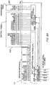
- FIGs. 8 there is illustrated a circuit schematic of a circuit board CB of the present invention including microprocessor 70 which may be an Intel 80C196.
- the microprocessor 70 is interfaced to the control panel OCP and programming panel SCP via operator interface circuitry 72 including appropriate shift registers and logic buffers which are self explanatory in the illustration.
- the microprocessor 70 includes the main CPU chip as well as an EPROM, RAM, "peripheral bus buffer and timer", a NVRAM, a "UART" leading to an input/output computer interface and series of opto isolators.
- the CPU outputs control signals ⁇ A, ⁇ B and "HOME" signals to the respective flavor valve position motor MF and the soda/water valve position motor MSW.
- the CPU also drives the PWM (pulse width modulation) stepper buffer to generate the signals ⁇ A, ⁇ B.
- Signals from the six flavor buttons on the soda water and still water buttons and thermistors TS are input through an analog multiplexor to the CPU.
- Other inputs include an input from a "flow accelerator lever” , input from the low CO2, no CO2, and recirculation bath over temperature sensors through an opto isolator in order illuminate the LED's adjacent to the associated legends on control panel OCP.
- Additional inputs to the microprocessor 70 are supplied from the six flavor, one soda and one water differential pressure sensing cells PS through a filter and a twelve bit analog to digital convertor having eight input channels.
- the operation of the circuit of Figs. 8 should be more clearly apparent from the foregoing description of Figs. 1 to 7 and following description of the software in the flow charts of Figs 9-15.
- Figs. 9 through 15 are the flow charts for the software for operating the microprocessor and associated circuitry of Figs. 8. Before describing these flow charts in detail, a general summary of the operation of the software for providing a closed loop ratio control routine will be described.
- the closed loop control is responsible for controlling the ratio of water to syrup, the portion size and the flow rate. Based on information programmed by the operator at installation, the microprocessor calculates the target flow rate for water and syrup based on the desired ratio, and the desired total flow rate. Once the target water and syrup flow rates have been calculated, the microprocessor begins ramping (gradually increasing) the reference flow rates stored in the microprocessor up to the target flow rate value. The microprocessor is continuously comparing the actual flow rate as measured by orifice flow meters (PS and orifice plates 48), to the reference flow rate. The difference, or error signal, is integrated two times, once in the software and once in the hardware. The output of the second integrator (or motor) is a position signal that is fed to the stepper control valve VSW or VF to either open or close it depending on whether the error signal is positive or negative.
- the adaptive scaling routine is responsive for increasing or decreasing the target flow originally programmed by the operator, depending on delivery capability of the fluid supply.
- the routine uses the valve position as the feedback signal for the scaling conrol. If either valve is open excessively, then the delivery capability is insufficient and the target flow is reduced. On the other hand, if either valve is closed excessively, the delivery capability is ample and the target flow rate is increased. The target flow rate is, however, never increased beyond the flow rate originally programmed. If both valves are at a nominal operating point, then the target flow rate is not changed.
- the invention presently uses a 5X5 matrix in conjunction with the valve position to implement the adaptive control algorithm. See Fig. 17.
- the soda and flavor average valve positions are each quantized into one of (but not limited to) five zones (0-20%, 21%-40%, 41%-60%, 61%-80%, 81%-100%). 9% corresponds to fully closed and 100% to fully open.
- the water average valve position thereby selects one of five columns and the flavor similarly selects one of five rows of the matrix resulting in the selection of the adaptive flow error. If the error is zero, then-the target flow is stable and is not changed, if the error is positive then the target flow is too low and is increased, and finally if the error is negative, the target flow is too high and is decreased.
- An important property of the matrix is the inclusion of several strategically plazed zero error cell entries corresponding to physically stable flow rates to prevent continually hunting between a lesser and a greater flow rate.
- the adaptive control matrix is referred to in algorithm 9 as ADAPT (row, col).
- the microprocessor If the microprocessor has scaled down the flow rate due to inadequate supply of water or syrup, the microprocessor will record this in a stack of data that can be reviewed by a service agent and the microprocessor will wink the light adjacent to the flavor button to indicate there is a problem with that flavor.
- the microprocessor integrates the total drink flow in the software. The output of this integrator is the volume that has been dispensed. When the volume integrator value equals the desired portion size, the microprocessor closes the water and syrup solenoid valves and then closes the water and syrup control valves so that they will be ready to ramp up for the next pour.
- the actual flow rate is determined from the sharp-edged orifice meter including differential pressure sensors PS and associated orifice discs 48. Orifice meters are placed in each of the conduits 36 including those for syrup, water and soda. Each orifice meter as described in the foregoing description of Figs. 5 and 6 includes a sharp-edged orifice in disc 48 mounted in a straight section of pipe, namely vertical bores 36. Pressure taps or bores are drilled through the valve control blocks into the bores 36 at positions upstream and downstream of the orifice and disc 48. A differential pressure sensor PS is connected to the pressure taps in positions indicated in Figs. 2 and 6. The differential pressure signal is amplified and fed into an analog multiplexer of Fig.
- the microprocessor can select one of the differential pressure sensors to read.
- the temperature sensor generates a temperature signal which is also fed into the multiplexer. Temperature of the liquids is measured because the viscosity of the liquid affects the differential pressure to flow rate relationship.
- the microprocessor contains a lookup table that gives flow rate based on differential pressure, syrup temperature, and syrup type.
- Each stepper is driven by two RIFA integrated circuits designed to control stepper motors (PWM stepper buffer of Figs. 8).
- the integrated circuit pair receives three signals from the microprocessor.
- stepper motors there are two stepper motors as illustrated above in Figs. 2 and 6 namely a stepper motor MSW and a flavor stepper motor MF.
- the microprocessor and associated circuitry of Figs. 8 in conjunction with the software of Figs. 9 to 13 also maintains a history of sales information and extensive diagnostic information in its volatile memory.
- the information can be downloaded to a computer for analysis through a modem (see hoset computer interface of Fig. 8).
- An intrinsic property of the type II controller used in the present invention is regulation to not only a target but also to the time integral of the target.
- the invention uses this property to permit simultaneous control of flow ratio (regulation to the target) and of portion size (regulation to the time integral of target) with a minimum of complexity.
- a particularly important feature of the present invention is the ramping of the reference signals, namely, the target flow rates of the respective syrups and water to achieve a selected ratio. Without ramping, the unit will open the solenoids 16 and control valves VSW, VF immediately trying to reach the target flow rate. The actual flow rate will be below the target flow rate at the beginning of a pour as the control valve opens. The actual flow rate will then have to "overshoot" the target flow rate to make up for the lower than target rate at the beginning of the pour. See Fig. 16A.
- the unit With ramping, the unit will still open the solenoids and open the control valves, but the reference flow rate will ramp up to the target flow rate. Since the actual flow rate also "ramps" due to opening of the control valve, the actual rate should not have to "overshoot” as much as in the case without ramping.
- the dispense time to deliver a given quantity of beverage will be slightly longer in the ramping mode but the advantages of ramping outweigh this small time increase.
- the ramping technique should be more accurate in terms of ratio control.
- the exact method of ramping may vary. Ramping may be from any given flow rate to the target flow rate. An alternative scheme would be to ramp from some percentage of the target (say 50%) to the target flow rate. The slope of the ramp may also vary depending on the type of fluid and the associated conduit sizes and other related parameters. See Fig. 16B.
- Fig. 9 an initialize routine begins with a decision block "NV RAM Check Sum Okay". If the decision is no, the routine proceeds to the block labeled "Update Prog from EPROM” where the program and the EPROM of Figs. 8 is updated. If the answer is yes, the routine proceeds to the block "Update Prog from NVRAM” where the program and the NVRAM is updated. The routine continues on to the decision block "Both Motors Home”. This block asks if the motors MSW and MF are both in the home positions, namely, the closed positions of the associated spool valves 32.
- the routine proceeds to the decision block "SODA PB?" to determine if the soda push button switch PBS is still actuated. If the answer is no the ratio controlled pour comes to an end, and if the answer is yes the ratio controlled pour proceeds to GO as indicated by the block "RCP GO".
- the software routine then proceeds on to the flow chart of Fig. 10 and the first step thereof labeled "SCAN SIZE PS".
- the size push button switches S, M, L and XL in Fig. 7 are scanned.
- the size push buttons are initialized in a similar manner to the push button switches of the proceeding subroutines.
- the routine goes on to the decision block "select PB depressed?"
- Subroutine OPT 6 is slightly different.
- This subroutine is a "LEARN" routine wherein the respective size selection buttons S,M,L,XL on the operator display panel OCP are energized; a beverage flavor is selected and the ratio controlled pour initialization routine for the selected flavor is run with the size button depressed until the cup is almost full.
- the amount of beverage dispensed into the cup is then displayed on display 60 and noted.
- each of the subroutines OPT 6 through OPT 9 are run to program the respective portions sizes into the microprocessors memory using the select button 62, increment button 64, decrement button 66 and display 60.
- Fig. 13 there is illustrated the ratio controlled pour initialization routine as a detailed step-by-step process.
- the pour time is illustrated as being a function of the volume and flow rate of each respective flavor selected.
- the next eight blocks illustrate the initial conditions for each of the following variables: "AVGPOS f " equals the average position of the flavor motor MF of Fig. 2 "AVGPOS s " equals the average position of the water motor MSW of Fig.
- TOTf equals the total volume of syrup "TOT s " equals the total volume of soda water or water
- IERR f equals the integral of the error of the flavor
- IERR s equals the integral of the error of the soda water-or water
- TARG FLV FLOW is the target or reference value of flavor flow rate for a given ratio
- TARG SODA FLOW equals the target soda or water flow rate for a given ratio.
- the ratio controlled pour initialization routine continues to a "soda" decision block which is an initialization control loop associated with the actuation of the soda push buttons PBS of Fig. 7.
- this control loop the water flow rate or soda water flow rates are selected via the controls of panel SCP the flow rates being represented in the software routine as "dp".
- the temperature and null values are selected.
- each of the flavors selected are initialized with respect to flow rate, temperature and null positions.
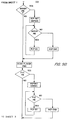
- the ratio control pour go program namely, the execution of an actual pour with appropriate ratio control routines of the present invention. That is, this flow chart illustrates the voltage ramping routine and the scaling down routine utilized when target flow rates cannot be achieved as illustrated in Fig. 15.
- the first control loop or loops comprise the voltage ramping subroutine.
- the software determines if the target flavor flow rate is equal to a the target flavor flow rate plus a step increment. If the answers is no, the routine proceeds on to the decision block "if TARG SODA FLOW ⁇ PROG".
- a scaling subroutine of the present invention designated "RCP END", namely the ratio control pour end routine.
- RCP END the ratio control pour end routine.
- the flavor and water solenoids are closed and no liquid is flowing.
- the flavor and solenoid motors are incremented in a negative direction at a maximum speed to the respective home positions.
- algorithm 9 is calculated: At the completion of the calculation of these algorithms the totals of water and flavor are calculated and stored.
Landscapes
- Physics & Mathematics (AREA)
- Chemical & Material Sciences (AREA)
- Analytical Chemistry (AREA)
- Fluid Mechanics (AREA)
- General Physics & Mathematics (AREA)
- Engineering & Computer Science (AREA)
- Automation & Control Theory (AREA)
- Devices For Dispensing Beverages (AREA)
Priority Applications (1)
| Application Number | Priority Date | Filing Date | Title |
|---|---|---|---|
| EP92118712A EP0530858A1 (de) | 1989-05-23 | 1990-05-11 | Durchfluss-Regelventilanordnung |
Applications Claiming Priority (3)
| Application Number | Priority Date | Filing Date | Title |
|---|---|---|---|
| US07/355,670 US4979639A (en) | 1989-05-23 | 1989-05-23 | Beverage dispenser control valve and ratio control method therefor |
| US355670 | 1989-05-23 | ||
| EP92118712A EP0530858A1 (de) | 1989-05-23 | 1990-05-11 | Durchfluss-Regelventilanordnung |
Related Parent Applications (1)
| Application Number | Title | Priority Date | Filing Date |
|---|---|---|---|
| EP90908353.7 Division | 1990-05-11 |
Publications (1)
| Publication Number | Publication Date |
|---|---|
| EP0530858A1 true EP0530858A1 (de) | 1993-03-10 |
Family
ID=26131159
Family Applications (1)
| Application Number | Title | Priority Date | Filing Date |
|---|---|---|---|
| EP92118712A Withdrawn EP0530858A1 (de) | 1989-05-23 | 1990-05-11 | Durchfluss-Regelventilanordnung |
Country Status (1)
| Country | Link |
|---|---|
| EP (1) | EP0530858A1 (de) |
Cited By (6)
| Publication number | Priority date | Publication date | Assignee | Title |
|---|---|---|---|---|
| WO1995034851A1 (en) * | 1994-06-10 | 1995-12-21 | Ecms, Inc. | Process for controlling the continuous metering of multiple additives into a product flow in sequence through a single flowmeter |
| WO1997003916A1 (en) * | 1995-07-15 | 1997-02-06 | Coca-Cola & Schweppes Beverages Limited | Drinks-dispensing apparatus |
| EP0852690A4 (de) * | 1995-09-29 | 1998-12-09 | Jimmy I Frank | Vorrichtung zur erzeugung von gefrorenen kohlensäurehaltigen getränke |
| GB2349866A (en) * | 1999-05-08 | 2000-11-15 | Imi Cornelius | Beverage dispenser with control of concentrate to diluent ratio |
| WO2004067443A1 (en) * | 2003-01-18 | 2004-08-12 | Global Agricultural Technology And Engineering, Llc | Soft drink dispensing system |
| CN100506683C (zh) * | 2003-01-18 | 2009-07-01 | 环球农业技术及工程有限公司 | 软饮料分配系统 |
Citations (5)
| Publication number | Priority date | Publication date | Assignee | Title |
|---|---|---|---|---|
| GB719692A (en) * | 1950-09-02 | 1954-12-08 | Meynell & Sons Ltd | Improvements in, or relating to, valves of the rotary cylindrical plug type |
| US3628566A (en) * | 1970-02-02 | 1971-12-21 | Clifford C Carse | Multiple fluid control device |
| FR2235338A1 (en) * | 1973-06-28 | 1975-01-24 | Serratto Angelo | Single-pipe air-conditioning system - has inlet and outlet unions connected to same secondary water pipe |
| EP0141874A1 (de) * | 1983-11-14 | 1985-05-22 | Hans Hermes Steuerungstechnik | Wegeventilvorrichtung |
| EP0313384A1 (de) * | 1987-10-23 | 1989-04-26 | The Coca-Cola Company | Abgabeventil für Getränke |
-
1990
- 1990-05-11 EP EP92118712A patent/EP0530858A1/de not_active Withdrawn
Patent Citations (5)
| Publication number | Priority date | Publication date | Assignee | Title |
|---|---|---|---|---|
| GB719692A (en) * | 1950-09-02 | 1954-12-08 | Meynell & Sons Ltd | Improvements in, or relating to, valves of the rotary cylindrical plug type |
| US3628566A (en) * | 1970-02-02 | 1971-12-21 | Clifford C Carse | Multiple fluid control device |
| FR2235338A1 (en) * | 1973-06-28 | 1975-01-24 | Serratto Angelo | Single-pipe air-conditioning system - has inlet and outlet unions connected to same secondary water pipe |
| EP0141874A1 (de) * | 1983-11-14 | 1985-05-22 | Hans Hermes Steuerungstechnik | Wegeventilvorrichtung |
| EP0313384A1 (de) * | 1987-10-23 | 1989-04-26 | The Coca-Cola Company | Abgabeventil für Getränke |
Cited By (9)
| Publication number | Priority date | Publication date | Assignee | Title |
|---|---|---|---|---|
| WO1995034851A1 (en) * | 1994-06-10 | 1995-12-21 | Ecms, Inc. | Process for controlling the continuous metering of multiple additives into a product flow in sequence through a single flowmeter |
| WO1997003916A1 (en) * | 1995-07-15 | 1997-02-06 | Coca-Cola & Schweppes Beverages Limited | Drinks-dispensing apparatus |
| US5967367A (en) * | 1995-07-15 | 1999-10-19 | Coca-Cola & Schweppes Beverages Limited | Drinks-dispensing apparatus |
| EP0852690A4 (de) * | 1995-09-29 | 1998-12-09 | Jimmy I Frank | Vorrichtung zur erzeugung von gefrorenen kohlensäurehaltigen getränke |
| GB2349866A (en) * | 1999-05-08 | 2000-11-15 | Imi Cornelius | Beverage dispenser with control of concentrate to diluent ratio |
| GB2349866B (en) * | 1999-05-08 | 2004-03-17 | Imi Cornelius | Beverage dispenser |
| WO2004067443A1 (en) * | 2003-01-18 | 2004-08-12 | Global Agricultural Technology And Engineering, Llc | Soft drink dispensing system |
| US7036686B2 (en) | 2003-01-18 | 2006-05-02 | Global Agricultural Technology And Engineering, Llc | Soft drink dispensing system |
| CN100506683C (zh) * | 2003-01-18 | 2009-07-01 | 环球农业技术及工程有限公司 | 软饮料分配系统 |
Similar Documents
| Publication | Publication Date | Title |
|---|---|---|
| US4979639A (en) | Beverage dispenser control valve and ratio control method therefor | |
| US6962270B1 (en) | Dosing valve with flow rate sensor for a beverage dispenser | |
| US5257720A (en) | Gasoline blending and dispensing system | |
| US6478192B2 (en) | Diluent change over dispense apparatus | |
| EP0433041B1 (de) | Kraftstoff-Abgabesystem | |
| US6685054B2 (en) | Apparatus and method for delivering liquids | |
| US6450369B1 (en) | Beverage dispenser | |
| AU756406B2 (en) | Beverage dispenser with modular volumetric valve system | |
| US7290680B2 (en) | Valve for dispensing two liquids at a predetermined ratio | |
| US4889148A (en) | Flow control valve for a dispensing system | |
| WO2001083360A3 (en) | Self-monitoring, intelligent fountain dispenser | |
| EP0358317A2 (de) | Zweikomponentensirupdosiersystem für Getränkeausgabeeinrichtungen | |
| EP0530858A1 (de) | Durchfluss-Regelventilanordnung | |
| EP1981804B1 (de) | Ausgabevorrichtung für nachträglich gemischte getränke | |
| EP1163185A1 (de) | Durchflussregelventil für einen getränkespender | |
| CA1253935A (en) | Method and apparatus for controlling temperature of a liquid | |
| JP3022636B2 (ja) | 給油装置 | |
| JP2001328700A (ja) | 飲料供給装置 | |
| JPS6335873A (ja) | 染液調合装置 | |
| JPH0665916B2 (ja) | 流量制御弁 | |
| JPH04347117A (ja) | シャワー制御装置 |
Legal Events
| Date | Code | Title | Description |
|---|---|---|---|
| PUAI | Public reference made under article 153(3) epc to a published international application that has entered the european phase |
Free format text: ORIGINAL CODE: 0009012 |
|
| AC | Divisional application: reference to earlier application |
Ref document number: 426819 Country of ref document: EP |
|
| AK | Designated contracting states |
Kind code of ref document: A1 Designated state(s): AT BE CH DE DK ES FR GB IT LI LU NL SE |
|
| STAA | Information on the status of an ep patent application or granted ep patent |
Free format text: STATUS: THE APPLICATION IS DEEMED TO BE WITHDRAWN |
|
| 18D | Application deemed to be withdrawn |
Effective date: 19930911 |