EP0531793A1 - Entraînement électrique d'essuie glace - Google Patents
Entraînement électrique d'essuie glace Download PDFInfo
- Publication number
- EP0531793A1 EP0531793A1 EP92114454A EP92114454A EP0531793A1 EP 0531793 A1 EP0531793 A1 EP 0531793A1 EP 92114454 A EP92114454 A EP 92114454A EP 92114454 A EP92114454 A EP 92114454A EP 0531793 A1 EP0531793 A1 EP 0531793A1
- Authority
- EP
- European Patent Office
- Prior art keywords
- windscreen wiper
- drive according
- wiper drive
- rotor
- wiping
- Prior art date
- Legal status (The legal status is an assumption and is not a legal conclusion. Google has not performed a legal analysis and makes no representation as to the accuracy of the status listed.)
- Granted
Links
Images


Classifications
-
- B—PERFORMING OPERATIONS; TRANSPORTING
- B60—VEHICLES IN GENERAL
- B60S—SERVICING, CLEANING, REPAIRING, SUPPORTING, LIFTING, OR MANOEUVRING OF VEHICLES, NOT OTHERWISE PROVIDED FOR
- B60S1/00—Cleaning of vehicles
- B60S1/02—Cleaning windscreens, windows or optical devices
- B60S1/04—Wipers or the like, e.g. scrapers
- B60S1/06—Wipers or the like, e.g. scrapers characterised by the drive
- B60S1/08—Wipers or the like, e.g. scrapers characterised by the drive electrically driven
Definitions
- the invention relates to an electric wiper drive, in particular for motor vehicles of the type specified in the preamble of claim 1.
- the previously known windshield wiper drives have electric motors, reduction gears and separate parking position devices.
- the gearbox is necessary to reduce the speed of the electromagnetic motors to the required wiping speed of 20 to 40 per minute.
- a disadvantage of this fixed gearbox is that the area and location in which the wiper operates is fixed. This gearbox also determines the relative wiping speed depending on the position of the wiper. In addition, the gearbox generates unpleasant and annoying noises and requires a lot of space. The gear housing of the wiper motor must therefore be very large.
- the invention has for its object to provide an electric wiper drive that operates with low noise and wear and is designed so that the gear housing is significantly reduced, the parking position and the wiping area of the wiper arm changed in a simple manner and adapted to given vehicle and environmental conditions can be.
- This object is achieved by the invention characterized in claim 1.
- the windshield wiper drive enables a freely controllable position of the windshield wiper with the simplest means, whereby a windshield wiper end position can be approached outside the normal wiping field or the position or size of the wiping area can be varied depending on the requirements.
- the wiper In winter operation, the wiper can only be wiped in the area in which windscreen heating is also effective. In heavy rainfall, it is possible to reduce the wiping area with the same or only slightly increased wiping speed in order to clear this area from water more frequently. In heavy rain, the drive of the wiper on the passenger side can be interrupted.
- the wiping quality and the service life of the wiper blades are increased.
- the ultrasonic motor By simply controlling the ultrasonic motor, it is possible to achieve a constant speed of the wiper blade in the entire wiping area, which is essential for good wiping quality.
- the windshield wiper drive is characterized by a low overall depth and by low costs. Since the new gearless drive works with storage frequencies in the ultrasonic range, no audible noise is generated.
- Figures 1 to 3 show an electric wiper drive, in particular for motor vehicles according to a preferred embodiment of the invention.
- the windshield wiper drive comprises a base plate 1 which, according to FIG. 1, has a flange part 3 by means of screw connections to the body of a motor vehicle in the region of the windshield or rear window can be attached.
- a self-locking ultrasonic motor 7 is firmly connected to the rear side 5 of this base plate 1 as an electromotive drive element with the aid of several screws 9, 11 or other fastening means.
- This ultrasonic motor 7 has a rotor 15 and a stator 17, which are surrounded by a cylindrical housing part 19, in a known manner.
- This housing part 19 is supported on a cylindrical projection 21 and rests with the end face 22 on the rear side 5 of the base plate 1, the housing part 19 being locked by means of screws 23.
- the housing part 19 protects the rotor 15 and the stator 17 against water, oil and dust as a cover part. This also prevents the ultrasound motor 7 from whistling.
- the end face 27 of the base plate 1 serves as a cooling device which emits the heat generated by the ultrasonic motor 7 directly to the body of the motor vehicle or via a heat dissipation plate 29 to the body. As a result, the life of the ultrasonic motor 7 is increased.
- the heat conducting plate 29 consists of a metal with good thermal conductivity.
- the ultrasonic motor 7 is arranged coaxially around a drive shaft 31.
- a plate spring 33 is fixedly arranged by means of a clamping ring 35.
- This clamping ring 35 is fixedly connected to the plate spring 33 via rivet connections 37, 39 and is supported by means of a press fit on a shoulder 41 of the drive shaft 31 1 is arranged.
- the plate spring 33 serves as a preloading device which presses the rotor 15 against the stator 17.
- This stator 17 comprises an elastic part 47 and a piezoelectric part 49.
- the end face 51 of the rotor is provided with an adhesive layer 53 which is pressed against the elastic part 47 of the stator 17.
- a thread 55 arranged on the drive shaft 31 protrudes from the roller bearing 43, which is surrounded by a cylindrical extension 57.
- a screw 59 and a counter screw 61 can be screwed onto this thread 55, as a result of which the contact pressure of the rotor 15 against the stator 17 can be precisely adjusted by means of the resilient plate spring 33.
- an axial bearing 63 and a pressure plate 65 are arranged between the end face 67 of the cylindrical extension 68 and the screw 59.
- the ultrasound motor 7 is connected to a control circuit 77 via a cable line 75.
- the base plate 1 is not directly connected to the body 79 of the vehicle, but an intermediate bearing piece 81 is also provided.
- the heat is dissipated by a heat dissipation plate 83 which is in contact with the body 79.
- the drive shaft 31 is also firmly connected to an extension shaft 85, which rotatably supports in a bearing 87 of the intermediate piece 81.
- the intermediate piece 81 projects with a cylindrical projection 89 through bores 93 in the body 79 and the glass pane 91.
- the intermediate piece 81 is fastened by means of a screw 97 that can be screwed onto a thread 95.
- the wiper 73 for the glass pane 91 is supported on the free end 99 of the extension shaft 85.
- the structure of the ultrasonic motor 7 is accordingly identical to FIG. 1.
- the ultrasonic motor 7 has a simple structure, is compact and allows quiet operation. Since the ultrasonic motor 7 is also easy to control, the windshield wiper 73 can be easily driven.
- FIG. 4 shows schematically the control of the motor 7 and thus of the windshield wiper 71 directly connected to it.
- a steering column switch 101 By pivoting a steering column switch 101 from the "OFF" position to the position 103, 105 or 107, different voltage signals are given to the control circuit 77, in which a microprocessor can be arranged, via only one bus line 109. Corresponding control signals are then given to the ultrasonic motor 7 via the cable line 75.
- This voltage coding as a simplified bus control according to FIG. 4 means that the wiper drive can be used in a variety of ways with regard to wiping speed.
- FIG. 5 shows a speed curve of the windshield wiper 71 and thus of the wiper lip arranged on it, it being evident that the wiper lip of the wiper blade is turned over slowly at the reversing point and the wiping speed is constant in the middle wiping area. This ensures a long service life for the wiper lip and thus the wiper blade.
- the new drive without gear also ensures optimal wiping quality.
- the wiping speed can thus be changed as a function of the rainfall and thus of the moistening of the pane 91, as can be seen in FIG. 6.
- an average wiping speed of 100 percent is selected, while in heavy rain the speed can be set to 120 percent to the medium speed and in drizzle to 80 percent to the medium speed.
- the wiping quality can also be increased by reducing or even shifting the wiping field size during heavy rainfall. In heavy rainfall, it is also not necessary to completely clear the passenger's field of vision from the rain.
- the wiping field size, the wiping field area and the wiping speed can be controlled via marking points 111 arranged on the rotor 15, which can be scanned by a position sensor 113 according to FIG. As a result, the position of the rotor 15 and thus of the windshield wiper 71 is determined.
- This position sensor is used to detect the park position of the windshield wiper 71 or the wiper zero position for numbering the position and for recognizing the marking points on the rotor 15 at which the speed varies and the wiper 71 is to be stopped.
- the position sensor 113 according to FIG. 4 scans marking points 111 arranged on the outer circumference 115 of the rotor 15.
- the end face 116 of the rotor 15 can of course also be scanned via a position sensor 117, the end face 116 then having to be provided with corresponding markings.
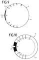
- FIG. 9 shows an embodiment for determining the position of the rotor 15 and thus the windshield wiper 71 connected directly to it, the marking points 111 being arranged on the outer circumference 115 of the rotor 15. These marking points are scanned by the position sensor 113, which is designed as an optical sensor and can differentiate between light and dark.
- the wide dark area 5A has the function of position numbering, while the other marking points 5B, 5C, 5D and 5E have the functions of changing the wiping speed and the wiper stop.
- the interpretation of the individual marking points depends on a control program in the control circuit 77, so that in normal wiping operation with a full wiping field when the markings 5D are reached, the wiping speed is slowly reduced to a minimum speed. With a reduced wiping area, the speed reduction already begins at the marking points 5C, while the direction of rotation is reversed at the marking points 5D. In the case of a shifted wiping field, the corresponding marking points 5B and 5C in one direction and 5D and 5E the corresponding marking points in the other direction. The parking position is always determined by the marking point 5F.
- the marking points 111 can be designed as light-dark points or as depressions, in which case the position sensor 113 must then be a distance sensor.
- the marking points 111 can also consist of other coding elements, which must then be scanned by a correspondingly designed scanning sensor.
- the marking points are arranged on the end face 116, which are scanned by the position sensor 117.
- the light-dark markings are designated 4A to 4F, the functions of which correspond to the markings 5A to 5F according to FIG. 9.
- the electric windshield wiper drive in particular for motor vehicles, is distinguished by the direct drive via the ultrasound motor 7 by a relatively small number of individual parts required, so that the drive can be produced in a cost-effective manner.
- the ultrasonic motor used in the invention operates quietly and has improved responsiveness, controllability and an improved efficiency.
- the service life of this motor is considerably improved by the existing cooling device of the ultrasonic motor 7.
- the gearless ultrasound motor also works with feed frequencies in the ultrasound range, which means that no audible noise is generated.
- this ultrasonic motor can be reversed very quickly, so that a reversal of the direction of rotation can be used to generate the reciprocating wiping movement.
- the wiping field size, the wiping field position and the wiping speeds can also be varied by freely selecting the reversing points depending on the desired requirements.
- the speed of the ultrasound motor or of the vibration drive can be varied depending on the position, which enables a uniform wiping movement in the middle wiping area to achieve good wiping quality with simultaneous sensitive reversing in the reversing area to achieve a long wiper blade life.
Landscapes
- Engineering & Computer Science (AREA)
- Mechanical Engineering (AREA)
- General Electrical Machinery Utilizing Piezoelectricity, Electrostriction Or Magnetostriction (AREA)
- Transmission Devices (AREA)
Applications Claiming Priority (2)
| Application Number | Priority Date | Filing Date | Title |
|---|---|---|---|
| DE4130065 | 1991-09-11 | ||
| DE4130065A DE4130065C2 (de) | 1991-09-11 | 1991-09-11 | Elektrischer Scheibenwischerantrieb |
Publications (2)
| Publication Number | Publication Date |
|---|---|
| EP0531793A1 true EP0531793A1 (fr) | 1993-03-17 |
| EP0531793B1 EP0531793B1 (fr) | 1995-11-15 |
Family
ID=6440274
Family Applications (1)
| Application Number | Title | Priority Date | Filing Date |
|---|---|---|---|
| EP92114454A Expired - Lifetime EP0531793B1 (fr) | 1991-09-11 | 1992-08-25 | Entraînement électrique d'essuie glace |
Country Status (5)
| Country | Link |
|---|---|
| US (1) | US5539269A (fr) |
| EP (1) | EP0531793B1 (fr) |
| JP (1) | JPH05193450A (fr) |
| DE (2) | DE4130065C2 (fr) |
| ES (1) | ES2083634T3 (fr) |
Cited By (8)
| Publication number | Priority date | Publication date | Assignee | Title |
|---|---|---|---|---|
| WO1993018944A1 (fr) * | 1992-03-23 | 1993-09-30 | Stefan Battlogg | Essuie-glace |
| DE19634559A1 (de) * | 1996-08-27 | 1998-03-05 | Teves Gmbh Alfred | Scheibenwischvorrichtung |
| DE19754843A1 (de) * | 1997-12-10 | 1999-06-24 | Bosch Gmbh Robert | Antriebsvorrichtung für ein zwischen Endstellungen bewegbares Teil eines Fahrzeugs und Verfahren zu ihrer Herstellung |
| US6737593B1 (en) * | 2000-07-28 | 2004-05-18 | Valeo Electrical Systems, Inc. | Non-reversing windshield wiper motor park switch |
| WO2009100785A1 (fr) * | 2008-02-14 | 2009-08-20 | Robert Bosch Gmbh | Blocage automatique électronique pour un dispositif essuie-glace |
| WO2016124416A1 (fr) * | 2015-02-05 | 2016-08-11 | Robert Bosch Gmbh | Unité d'entraînement pour un système d'essuie-glace |
| CN111200349A (zh) * | 2020-02-11 | 2020-05-26 | 南通大学 | 一种高精度定位的复合式电机 |
| EP4377163A1 (fr) * | 2021-07-30 | 2024-06-05 | Valeo Systemes D'essuyage | Dispositif d'essuyage d'une vitre de véhicule automobile |
Families Citing this family (10)
| Publication number | Priority date | Publication date | Assignee | Title |
|---|---|---|---|---|
| DE19962646A1 (de) * | 1999-12-23 | 2001-06-28 | Siegmund Kramer | Fahrzeug, insbesondere Kraftfahrzeug, mit einem Scheibenwischsystem |
| DE10009797B4 (de) * | 2000-03-01 | 2008-05-15 | Valeo Auto-Electric Wischer Und Motoren Gmbh | Scheibenwischervorrichtung zum Wischen von Scheiben |
| DE10153173B4 (de) * | 2001-02-27 | 2019-09-05 | Robert Bosch Gmbh | Elektrischer Antrieb mit einem Wärmeleitelement zur Wärmeabführung von einer elektrischen Schaltung |
| JP2003011786A (ja) * | 2001-04-23 | 2003-01-15 | Mitsuba Corp | ワイパ装置及び自動車用リヤワイパ |
| US7676880B2 (en) * | 2002-05-15 | 2010-03-16 | Trico Products Corporation | Direct drive windshield wiper assembly |
| DE10360117A1 (de) * | 2003-12-20 | 2005-06-30 | Daimlerchrysler Ag | Scheibenwischeranlage |
| DE102005050774A1 (de) * | 2005-10-24 | 2007-04-26 | Robert Bosch Gmbh | Scheibenwischanlage mit einer im Ruhezustand eines Wischerantriebs wirksamen Selbsthemmung |
| JP5383311B2 (ja) * | 2008-05-20 | 2014-01-08 | アスモ株式会社 | ワイパモータ及びワイパ装置 |
| DE102020214174A1 (de) | 2020-11-11 | 2022-05-12 | Robert Bosch Gesellschaft mit beschränkter Haftung | Wischerantriebsvorrichtung, Fahrzeug, Wischerantriebseinheit und Verfahren zur Montage einer Wischerantriebsvorrichtung |
| JP7435912B2 (ja) * | 2021-05-14 | 2024-02-21 | 株式会社デンソー | 車両用ワイパ装置及び車両用ワイパ装置の制御方法 |
Citations (4)
| Publication number | Priority date | Publication date | Assignee | Title |
|---|---|---|---|---|
| EP0184312A2 (fr) * | 1984-12-06 | 1986-06-11 | General Motors Corporation | Appareil de commande d'un système d'essuie-glace de véhicule |
| US4866357A (en) * | 1988-12-19 | 1989-09-12 | Ford Motor Company | Windshield wiper and control system |
| US4980599A (en) * | 1989-02-15 | 1990-12-25 | Aisin Seiki Kabushiki Kaisha | Ultrasonic motor |
| DE4131948A1 (de) * | 1990-09-27 | 1992-04-02 | Aisin Seiki | Ultraschall-motor und vibrationsteil hierfuer |
Family Cites Families (25)
| Publication number | Priority date | Publication date | Assignee | Title |
|---|---|---|---|---|
| JPS5937672B2 (ja) * | 1979-03-19 | 1984-09-11 | 年生 指田 | 超音波振動を利用した回転駆動装置 |
| CA1208269A (fr) * | 1982-02-25 | 1986-07-22 | Toshiiku Sashida | Dispositif moteur a oscillation ultrasonique |
| DE3208121A1 (de) * | 1982-03-06 | 1983-09-08 | Robert Bosch Gmbh, 7000 Stuttgart | Scheibenwischvorrichtung fuer fahrzeuge |
| US4560263A (en) * | 1982-12-03 | 1985-12-24 | Canon Kabushiki Kaisha | Drive system for a vibration wave motor for lens control |
| US4727276A (en) * | 1985-03-26 | 1988-02-23 | Canon Kabushiki Kaisha | Driving circuit for vibration wave motor |
| US4794294A (en) * | 1986-06-12 | 1988-12-27 | Canon Kabushiki Kaisha | Vibration wave motor |
| US5136215A (en) * | 1986-12-15 | 1992-08-04 | Canon Kabushiki Kaisha | Driving circuit for vibration wave motor |
| JPS6423778A (en) * | 1987-07-15 | 1989-01-26 | Seiko Instr & Electronics | Surge motor driving circuit |
| JPS6474148A (en) * | 1987-09-16 | 1989-03-20 | Ichikoh Industries Ltd | Door window wiper |
| JP2611296B2 (ja) * | 1987-12-29 | 1997-05-21 | アイシン精機株式会社 | 超音波モータ |
| JP2537267B2 (ja) * | 1988-05-30 | 1996-09-25 | キヤノン株式会社 | 振動型アクチュエ―タ―装置 |
| JPH0241677A (ja) * | 1988-07-29 | 1990-02-09 | Aisin Seiki Co Ltd | 超音波モータ |
| US5023526A (en) * | 1988-10-31 | 1991-06-11 | Aisin Seiki Kabushiki Kaisha | Vibratory motor |
| JPH02158440A (ja) * | 1988-12-09 | 1990-06-18 | Honda Electron Co Ltd | 自動車塔載装置の駆動装置 |
| JPH0336969A (ja) * | 1989-06-29 | 1991-02-18 | Aisin Seiki Co Ltd | 超音波モータ |
| DE69013263T2 (de) * | 1989-08-03 | 1995-06-08 | Asmo Co Ltd | Methode und Vorrichtung zur Steuerung eines Ultraschallmotors. |
| US5155418A (en) * | 1989-10-16 | 1992-10-13 | Canon Kabushiki Kaisha | Actuator device |
| US5053670A (en) * | 1989-11-20 | 1991-10-01 | Canon Kabushiki Kaisha | Precision actuator |
| US5258694A (en) * | 1989-12-15 | 1993-11-02 | Alps Electric Co., Ltd. | Control device for ultrasonic motor |
| JPH03253272A (ja) * | 1990-03-01 | 1991-11-12 | Canon Inc | 振動波モータ |
| US5225734A (en) * | 1990-03-01 | 1993-07-06 | Canon Kabushiki Kaisha | Vibration wave driven motor |
| JP2898053B2 (ja) * | 1990-03-28 | 1999-05-31 | キヤノン株式会社 | 振動波装置 |
| JP2723333B2 (ja) * | 1990-04-12 | 1998-03-09 | アルプス電気株式会社 | 超音波モータの制御装置 |
| JP2862634B2 (ja) * | 1990-05-25 | 1999-03-03 | アスモ株式会社 | 超音波モータ |
| EP0791969A1 (fr) * | 1991-08-22 | 1997-08-27 | Mitsubishi Jukogyo Kabushiki Kaisha | Système de contrÔle pour moteur à ultrasons |
-
1991
- 1991-09-11 DE DE4130065A patent/DE4130065C2/de not_active Expired - Fee Related
-
1992
- 1992-08-25 DE DE59204331T patent/DE59204331D1/de not_active Expired - Fee Related
- 1992-08-25 ES ES92114454T patent/ES2083634T3/es not_active Expired - Lifetime
- 1992-08-25 EP EP92114454A patent/EP0531793B1/fr not_active Expired - Lifetime
- 1992-09-10 JP JP4242017A patent/JPH05193450A/ja active Pending
-
1994
- 1994-10-18 US US08/323,680 patent/US5539269A/en not_active Expired - Fee Related
Patent Citations (4)
| Publication number | Priority date | Publication date | Assignee | Title |
|---|---|---|---|---|
| EP0184312A2 (fr) * | 1984-12-06 | 1986-06-11 | General Motors Corporation | Appareil de commande d'un système d'essuie-glace de véhicule |
| US4866357A (en) * | 1988-12-19 | 1989-09-12 | Ford Motor Company | Windshield wiper and control system |
| US4980599A (en) * | 1989-02-15 | 1990-12-25 | Aisin Seiki Kabushiki Kaisha | Ultrasonic motor |
| DE4131948A1 (de) * | 1990-09-27 | 1992-04-02 | Aisin Seiki | Ultraschall-motor und vibrationsteil hierfuer |
Non-Patent Citations (2)
| Title |
|---|
| PATENT ABSTRACTS OF JAPAN vol. 13, no. 281 (M-842)(3629) 27. Juni 1989 & JP-A-01 074 148 ( ICHIKOH ) 20. März 1989 * |
| PATENT ABSTRACTS OF JAPAN vol. 14, no. 410 (M-1020)5. September 1990 & JP-A-02 158 440 ( HONDA ELECTRON CO. ) 18. Juni 1990 * |
Cited By (11)
| Publication number | Priority date | Publication date | Assignee | Title |
|---|---|---|---|---|
| WO1993018944A1 (fr) * | 1992-03-23 | 1993-09-30 | Stefan Battlogg | Essuie-glace |
| US5588173A (en) * | 1992-03-23 | 1996-12-31 | Battlogg; Stefan | Windshield wiper system with electric motor |
| DE19634559A1 (de) * | 1996-08-27 | 1998-03-05 | Teves Gmbh Alfred | Scheibenwischvorrichtung |
| DE19754843A1 (de) * | 1997-12-10 | 1999-06-24 | Bosch Gmbh Robert | Antriebsvorrichtung für ein zwischen Endstellungen bewegbares Teil eines Fahrzeugs und Verfahren zu ihrer Herstellung |
| US6737593B1 (en) * | 2000-07-28 | 2004-05-18 | Valeo Electrical Systems, Inc. | Non-reversing windshield wiper motor park switch |
| WO2009100785A1 (fr) * | 2008-02-14 | 2009-08-20 | Robert Bosch Gmbh | Blocage automatique électronique pour un dispositif essuie-glace |
| WO2016124416A1 (fr) * | 2015-02-05 | 2016-08-11 | Robert Bosch Gmbh | Unité d'entraînement pour un système d'essuie-glace |
| CN107206969A (zh) * | 2015-02-05 | 2017-09-26 | 罗伯特·博世有限公司 | 用于刮水器系统的驱动单元 |
| CN111200349A (zh) * | 2020-02-11 | 2020-05-26 | 南通大学 | 一种高精度定位的复合式电机 |
| CN111200349B (zh) * | 2020-02-11 | 2021-04-23 | 南通大学 | 一种高精度定位的复合式电机 |
| EP4377163A1 (fr) * | 2021-07-30 | 2024-06-05 | Valeo Systemes D'essuyage | Dispositif d'essuyage d'une vitre de véhicule automobile |
Also Published As
| Publication number | Publication date |
|---|---|
| EP0531793B1 (fr) | 1995-11-15 |
| DE59204331D1 (de) | 1995-12-21 |
| DE4130065C2 (de) | 1993-12-02 |
| DE4130065A1 (de) | 1993-03-25 |
| JPH05193450A (ja) | 1993-08-03 |
| ES2083634T3 (es) | 1996-04-16 |
| US5539269A (en) | 1996-07-23 |
Similar Documents
| Publication | Publication Date | Title |
|---|---|---|
| EP0531793B1 (fr) | Entraînement électrique d'essuie glace | |
| DE10144985B4 (de) | Verfahren zur Steuerung einer Scheibenwischvorrichtung sowie eine Scheibenwischvorrichtung für ein Kraftfahrzeug | |
| DE69919837T2 (de) | Scheibenwischervorrichtung und Verfahren zur variablen Einstellung der Bewegung des Wischblatts | |
| DE10113678A1 (de) | Wischeranlage mit zwei Scheibenwischern | |
| DE102007031508B4 (de) | Motor und Wischervorrichtung, die den Motor enthält | |
| WO1990005654A2 (fr) | Essuie-glace pour vehicules a moteur | |
| DE102018132465B4 (de) | Rückstellmomenterzeugungsvorrichtung für ein Kraftfahrzeug | |
| WO2008049536A1 (fr) | Procédé de commande du mouvement d'un bras d'essuie-glace d'un système essuie-glace pour des vitres de véhicule | |
| WO2003047929A1 (fr) | Dispositif d'essuie-glace notamment destine a un vehicule | |
| EP0207404B1 (fr) | Dispositif d'essuie-glace | |
| DE10244432A1 (de) | Drehaktor und Verfahren zum Steuern eines Aktors | |
| EP2011703A2 (fr) | Dispositif d'essuie-glace | |
| WO1998012097A1 (fr) | Dispositif de direction electriquement assistee | |
| EP0838371B1 (fr) | Rétroviseur extérieur pour véhicule | |
| DE102008042706A1 (de) | Antriebsvorrichtung | |
| DE3707837C2 (fr) | ||
| DE2900166A1 (de) | Scheibenwischeranlage | |
| DE10338662B4 (de) | Scheibenwischeranlage für ein Kraftfahrzeug | |
| DE102005045921B4 (de) | Verfahren zum Wischen einer Scheibe sowie Scheibenwischvorrichtung, insbesondere für ein Kraftfahrzeug | |
| EP1037776B1 (fr) | Dispositif d'essuie-glace | |
| WO2010040604A1 (fr) | Dispositif d'entraînement | |
| EP1908654A1 (fr) | Dispositif d'essuie-glaces | |
| DE3335919A1 (de) | Antrieb, insbesondere fuer den wischer einer kraftfahrzeugscheibe | |
| DE102004010118A1 (de) | Wischarmantriebsvorrichtung | |
| DE102022205339A1 (de) | Scheibenwischervorrichtung, Scheibenwischanlage und Verfahren zum Betrieb einer Scheibenwischervorrichtung |
Legal Events
| Date | Code | Title | Description |
|---|---|---|---|
| PUAI | Public reference made under article 153(3) epc to a published international application that has entered the european phase |
Free format text: ORIGINAL CODE: 0009012 |
|
| AK | Designated contracting states |
Kind code of ref document: A1 Designated state(s): DE ES FR GB IT |
|
| 17P | Request for examination filed |
Effective date: 19930624 |
|
| 17Q | First examination report despatched |
Effective date: 19940803 |
|
| GRAA | (expected) grant |
Free format text: ORIGINAL CODE: 0009210 |
|
| AK | Designated contracting states |
Kind code of ref document: B1 Designated state(s): DE ES FR GB IT |
|
| PG25 | Lapsed in a contracting state [announced via postgrant information from national office to epo] |
Ref country code: IT Free format text: LAPSE BECAUSE OF FAILURE TO SUBMIT A TRANSLATION OF THE DESCRIPTION OR TO PAY THE FEE WITHIN THE PRESCRIBED TIME-LIMIT;WARNING: LAPSES OF ITALIAN PATENTS WITH EFFECTIVE DATE BEFORE 2007 MAY HAVE OCCURRED AT ANY TIME BEFORE 2007. THE CORRECT EFFECTIVE DATE MAY BE DIFFERENT FROM THE ONE RECORDED. Effective date: 19951115 |
|
| REF | Corresponds to: |
Ref document number: 59204331 Country of ref document: DE Date of ref document: 19951221 |
|
| ET | Fr: translation filed | ||
| GBT | Gb: translation of ep patent filed (gb section 77(6)(a)/1977) |
Effective date: 19960226 |
|
| REG | Reference to a national code |
Ref country code: ES Ref legal event code: FG2A Ref document number: 2083634 Country of ref document: ES Kind code of ref document: T3 |
|
| PG25 | Lapsed in a contracting state [announced via postgrant information from national office to epo] |
Ref country code: GB Effective date: 19960825 |
|
| PLBE | No opposition filed within time limit |
Free format text: ORIGINAL CODE: 0009261 |
|
| 26N | No opposition filed | ||
| GBPC | Gb: european patent ceased through non-payment of renewal fee |
Effective date: 19960825 |
|
| REG | Reference to a national code |
Ref country code: FR Ref legal event code: ST |
|
| REG | Reference to a national code |
Ref country code: ES Ref legal event code: PC2A |
|
| REG | Reference to a national code |
Ref country code: FR Ref legal event code: RN |
|
| REG | Reference to a national code |
Ref country code: GB Ref legal event code: 728V |
|
| REG | Reference to a national code |
Ref country code: FR Ref legal event code: FC |
|
| REG | Reference to a national code |
Ref country code: FR Ref legal event code: TP |
|
| REG | Reference to a national code |
Ref country code: GB Ref legal event code: 7281 |
|
| PGFP | Annual fee paid to national office [announced via postgrant information from national office to epo] |
Ref country code: ES Payment date: 19990810 Year of fee payment: 8 |
|
| PGFP | Annual fee paid to national office [announced via postgrant information from national office to epo] |
Ref country code: FR Payment date: 19990826 Year of fee payment: 8 |
|
| PGFP | Annual fee paid to national office [announced via postgrant information from national office to epo] |
Ref country code: DE Payment date: 19990930 Year of fee payment: 8 |
|
| PG25 | Lapsed in a contracting state [announced via postgrant information from national office to epo] |
Ref country code: ES Free format text: LAPSE BECAUSE OF NON-PAYMENT OF DUE FEES Effective date: 20000826 |
|
| PG25 | Lapsed in a contracting state [announced via postgrant information from national office to epo] |
Ref country code: FR Free format text: LAPSE BECAUSE OF NON-PAYMENT OF DUE FEES Effective date: 20010430 |
|
| PG25 | Lapsed in a contracting state [announced via postgrant information from national office to epo] |
Ref country code: DE Free format text: LAPSE BECAUSE OF NON-PAYMENT OF DUE FEES Effective date: 20010501 |
|
| REG | Reference to a national code |
Ref country code: FR Ref legal event code: ST |
|
| REG | Reference to a national code |
Ref country code: ES Ref legal event code: FD2A Effective date: 20010911 |