EP0532028B1 - Sich schneidende, zweiseitig gerichtete Becher für ein Becherförder-System - Google Patents
Sich schneidende, zweiseitig gerichtete Becher für ein Becherförder-System Download PDFInfo
- Publication number
- EP0532028B1 EP0532028B1 EP92115577A EP92115577A EP0532028B1 EP 0532028 B1 EP0532028 B1 EP 0532028B1 EP 92115577 A EP92115577 A EP 92115577A EP 92115577 A EP92115577 A EP 92115577A EP 0532028 B1 EP0532028 B1 EP 0532028B1
- Authority
- EP
- European Patent Office
- Prior art keywords
- buckets
- bucket
- guide
- horizontal
- contact
- Prior art date
- Legal status (The legal status is an assumption and is not a legal conclusion. Google has not performed a legal analysis and makes no representation as to the accuracy of the status listed.)
- Expired - Lifetime
Links
Images


Classifications
-
- B—PERFORMING OPERATIONS; TRANSPORTING
- B65—CONVEYING; PACKING; STORING; HANDLING THIN OR FILAMENTARY MATERIAL
- B65G—TRANSPORT OR STORAGE DEVICES, e.g. CONVEYORS FOR LOADING OR TIPPING, SHOP CONVEYOR SYSTEMS OR PNEUMATIC TUBE CONVEYORS
- B65G47/00—Article or material-handling devices associated with conveyors; Methods employing such devices
- B65G47/34—Devices for discharging articles or materials from conveyor
- B65G47/38—Devices for discharging articles or materials from conveyor by dumping, tripping, or releasing load carriers
- B65G47/40—Devices for discharging articles or materials from conveyor by dumping, tripping, or releasing load carriers by tilting conveyor buckets
-
- B—PERFORMING OPERATIONS; TRANSPORTING
- B65—CONVEYING; PACKING; STORING; HANDLING THIN OR FILAMENTARY MATERIAL
- B65G—TRANSPORT OR STORAGE DEVICES, e.g. CONVEYORS FOR LOADING OR TIPPING, SHOP CONVEYOR SYSTEMS OR PNEUMATIC TUBE CONVEYORS
- B65G47/00—Article or material-handling devices associated with conveyors; Methods employing such devices
- B65G47/52—Devices for transferring articles or materials between conveyors i.e. discharging or feeding devices
- B65G47/56—Devices for transferring articles or materials between conveyors i.e. discharging or feeding devices to or from inclined or vertical conveyor sections
- B65G47/58—Devices for transferring articles or materials between conveyors i.e. discharging or feeding devices to or from inclined or vertical conveyor sections for materials in bulk
-
- B—PERFORMING OPERATIONS; TRANSPORTING
- B65—CONVEYING; PACKING; STORING; HANDLING THIN OR FILAMENTARY MATERIAL
- B65G—TRANSPORT OR STORAGE DEVICES, e.g. CONVEYORS FOR LOADING OR TIPPING, SHOP CONVEYOR SYSTEMS OR PNEUMATIC TUBE CONVEYORS
- B65G2201/00—Indexing codes relating to handling devices, e.g. conveyors, characterised by the type of product or load being conveyed or handled
- B65G2201/02—Articles
- B65G2201/0202—Agricultural and processed food products
- B65G2201/0211—Fruits and vegetables
Definitions
- This invention has to do with bucket conveyors for use in material handling situations. More specifically this invention has to do with an improved bucket design that allows a bucket conveyor to be bi-directionally driven so that buckets can be unloaded while the system is traveling "forward" or “backward” while still maintaining a seal between the edges of adjacent buckets during times when a seal is desired.
- Prior art buckets for bucket conveyors are designed with overlaying flanges to provide a sealed area between buckets however such overlapping flanges prevent the buckets from being "bi-directional".
- the overlapping flanges of the prior art devices must be removed (which causes leakage at infeed points) or requires the addition of a separate, driven and syncronized overlapping flange and chain combination in the feed area.
- the edges of adjacent buckets overlap throughout much of the bucket travel path so that the buckets have to undergo a tail change or a reversal of their overlap at two locations in the cause of their travel; the buckets as well as the whole bucket distribution system can be operated only in one direction.
- the buckets provided herein do not rely on gravity to swing into positions such as to load or to dump their load but use a number of bosses molded to the bucket to guide and control the attitude of the bucket throughout the bucket's travel around a plurality of turning sprockets and through loading and unloading stations.
- the buckets of the instand invention are cast with a reverse curve lip that adds stiffness to the bucket walls.
- This reverse curve lip does away with the need for a longitudinal rib along the discharge lip and allows heretofore unmoldable bucket lengths to be molded without the need for transverse ribs to stiffen the bucket walls.
- the basic invention herein centers around the specific configuration of the buckets of the bucket elevator system.
- the bucket design allows various rail and guide members to interface with the bucket.
- the design also allows these buckets to be moved either forward or backward with equal facility and utility. That is to say, the entire system of buckets and drive chain to which the buckets are attached can be driven in either a forward direction or a reverse direction and the filling and unloading can be accompished as determined by the set up of the bucket transport system.
- the bucket used to transport any type of flowable products such as grains, sand, potato chips, spices, fruit fillings, ore, liquids, powders, sludge, etc., is an open top container having a first end wall 12, a second end wall 14, connected together and separated by a curvalinear container web 16, further housing a reverse curve portion 18, connected to each end wall to form the open top container.
- the bucket 10 has a significant structural reinforced edge made up of portions 20 along the upper edge of second end wall 14, portion 22 along the upper, normally leading edge of the curvalinear containment web 16, portion 24 along the upper edge of first end wall 12 and portion 26 along the upper, normally trailing edge of the curvalinear containment web 16.
- the bucket 10 also has several appendages that are used to guide the bucket as it is being transported through a bucket lift system.
- These appendages include a contact pad 30 affixed to or integrally formed with the bucket.
- the contact pad 30, in a preferred embodiment, is proximate the first end wall 12 but inboard thereof on the bottom of the curvalinear containment web 16.
- Other locations for the contact pad as well as complete elimination of the contact pad are alternative embodiments contemplated by the inventor.
- Three appendages are formed on the first end wall 12. These include leading guide boss 32 located on the outside of the first end wall 12 some distance below the structural portion 24 along the upper edge of the first end wall.
- a second guide boss a trailing guide boss 34, is attached to an upper area of the first end wall 12 near the zone where the structural portion 26 along the upper normally trailing edge of the curvalinear containment web 16 is located.
- the third appendage is a primary guide boss 36 integral with or affixed to the first end wall 12. This primary guide boss 36 extends upward to the upper edge of the portion 24 along the upper edge of the first end wall and out from the major planar surface of the first end wall 12.
- the primary guide boss 36 includes a guide surface 40 at a relatively lower portion of the primary guide boss 36.
- a chain attachment plinth 42 provided with at least one aperture in the preferred embodiment shown, is accommodated on the primary guide boss 36.
- a bucket cam element 44 On the outboard surface of the second end wall 14, as best seen in Figure 2, is a bucket cam element 44.
- the bucket cam element 44 is formed integral with the bucket 10 or subsequently affixed to the outboard surface of the second end wall 14.
- This bucket cam element 44 includes an upper surface 46 which is the same relative height as the upper surface of the portion 20 of the upper edge of the second end wall.
- the bucket cam element 44 also includes a primary cam 50 at the relatively lower end of the bucket cam element 44.
- a chain attachment plinth 52 may also be formed on or affixed to the outboard surface of the bucket cam element between the primary cam 50 and the upper surface 46 of the bucket cam element.
- the structural portion 26 along the upper normally trailing edge of the curvalinear containment web is a reinforced edge of significant dimension. This reinforced edge 26 eliminates the need for a stiffening web on the exterior of the curvalinear containment web below the upper normally trailing edge of the curvalinear containment web.
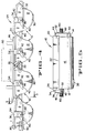
- FIG 4 A normal arrangement of buckets is shown in Figure 4.
- the buckets are supported between two continous chains such as 80 by means of chain pivot attachment means 82 which interact with the apertures in the primary guide boss 36 and bucket cam element 44.
- the chain nearest the viewer in Figure 4 has been removed for clarity.
- Shown in Figure 4 is a guide rail 90 along which the guide surface of the primary guide boss 40 rides and keeps the bucket generally 10 somewhat skewed from horizontal.
- engagement with rail 90 will terminate and engagement between surface 54, the upper surface of the primary guide boss, will commence with the rail 86.
- the buckets 10 will be held horizontal under rail 86 as they pass under a feed zone 60.
- This nesting or overlap allows the buckets to be filled from the fill spout 60 without material being dropped between the buckets and without the need for a separate blocking plate between buckets.
- Figure 5 simply presents a front elevation of a bucket showing how chains 80 are mounted to the bucket, or vice versa by means of chain pivot attachment means 82.
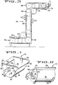
- a typical lift system generally 56 is shown somewhat diagramatically.
- the various zones of concern in this figure include the feed zone 60 discussed above; a horizontal to vertical transition zone 64; a vertical to horizontal transition zone 65; an unloading zone 70, which may include a product deflector 62; a horizontal to vertical transition zone 72, a zone where buckets are transported in a rotated position; a vertical to horizontal transition zone 74; and a change of direction zone 78 just before the feed zone 60.
- Each of these zones are shown in Figures 4, and 6-13 as well as several alternative bucket manipulation operations.
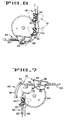
- Figure 7 shows a series of buckets 10 in a transition station generally 66.
- the trailing guide boss 34 will be fed into the guide track 96 which will guide the bucket through the turn from vertical to horizontal.
- boss 34 is disengaged from track 96 boss 32 will become engaged with guide rail 100 to assist in maintaining the bucket 10 in a generally horizontal deployment.
- FIG 8 presents an alternative unloading scheme.
- the buckets 10 are unloaded while traveling in a horizontal path by means of a cam 104 which is placed to interact with the primary cam 50 of the bucket 10.
- the cams will interact such that the bucket is tilted out of horizontal to near vertical and the load 106 will be spilled out of the bucket.
- Figure 10 is another unloading scheme. This time the buckets are traveling in the direction opposite the direction shown in Figures 8 and 9.
- One advantage of this invention is that the buckets can go either forward or backward with equal facility.
- a cam 116 interacts with a portion of the primary cam 50 to cause the bucket to tip away from the normal direction of travel and thus empty the load from the bucket 10.
- Figure 11 shows the transition zone generally 74 where the buckets are translated from moving vertically downward in a rotated position to a horizontal position where the buckets are horizontal.
- Guide rail 120 interacting with the guide surface 40 keeps the buckets rotated ninety degrees from horizontal.
- guide rail 122 holds the bucket in a preferred position.
- the leading guide boss 32 contacts guide rail 124 and flips the bucket to a horizontal position and through contact with the guide surface 40 the guide rail 124 holds the bucket in a horizontal position as shown in Figure 11.
Landscapes
- Engineering & Computer Science (AREA)
- Mechanical Engineering (AREA)
- Chain Conveyers (AREA)
- Intermediate Stations On Conveyors (AREA)
Claims (4)
- Eimerfördersystem mit einer Vielzahl von Eimern (10), welche zwischen zwei Endlosketten (80) getragen sind, Führungseinrichtungen, um mit den Eimern in Wechselwirkung zu treten, und Antriebseinrichtungen (94) zum Betätigen des Systems, wobei die Eimer (10) sich verschachtelnde Führungs- und Nachlaufränder (22, 26) aufweisen, welche mit benachbarten Eimern zusammenwirken, um eine Dichtung zwischen den benachbarten Eimern zu bilden, wenn die Eimer in einer horizontalen Position sind,
dadurch gekennzeichnet, daßa) die Antriebseinrichtung (94) in der Lage ist, das System in zwei Richtungen derart zu betätigen, daß die Eimer (10) in einer ersten und in einer nachfolgenden zweiten Richtung bewegt werden können;b) die Eimer (10) einen erhabenen Primärführungsbeschlag (36) mit einer oberen Oberfläche (54) und einer unteren Führungsfläche (40) daran aufweisen,i) wobei der erhabene Führungsbeschlag (36), welcher dem Eimerfördersystem zugeordnet ist, so angeordnet ist, daß er in Kontakt mit der oberen Oberfläche (54) ist, wenn die Eimer in einer gezwungenen Position eines linearen Transportweges durch die Führungseinrichtung (86) gehalten werden, undii) die benachbarten Eimer (10) außer Kontakt sind, wenn die Führungseinrichtung (86) nicht in Kontakt mit der oberen Oberfläche (54) des erhabenen Primärführungsbeschlages (36) des Eimers ist. - Eimerfördersystem nach Anspruch 1, bei welchem die Führungseinrichtung (86) eine Führungsschiene aufweist, um zu verhindern, daß die Eimer schwingen, wenn sie durch einen gekrümmten Weg laufen.
- Eimerfördersystem nach Anspruch 1, bei welchem die Eimer ein zweites Nockenelement (44) zwischen den zwei Endlosketten (80) mittels einer Kettendrehbefestigungseinrichtung (82) aufweisen, welche mit den Öffnungen in dem erhabenen Primärführungsbeschlag (36) und dem zweiten Nockenelement (44) zusammenwirken, welches erhabene Führungsbeschläge (34) und (32) aufweist.
- Eimerfördersystem nach einem der Ansprüche 1 bis 3, bei welchem die Eimer ineinander in einer engen zueinander passenden überlappenden Anordnung drehen können, wenn die Eimer (10) derart gedreht werden, daß eine obere Oberfläche (20) jedes Eimers parallel zu einer Führungsschiene in Kontakt mit jedem Eimer ist.
Applications Claiming Priority (2)
| Application Number | Priority Date | Filing Date | Title |
|---|---|---|---|
| US76078091A | 1991-09-13 | 1991-09-13 | |
| US760780 | 1991-09-13 |
Publications (2)
| Publication Number | Publication Date |
|---|---|
| EP0532028A1 EP0532028A1 (de) | 1993-03-17 |
| EP0532028B1 true EP0532028B1 (de) | 1996-05-15 |
Family
ID=25060174
Family Applications (1)
| Application Number | Title | Priority Date | Filing Date |
|---|---|---|---|
| EP92115577A Expired - Lifetime EP0532028B1 (de) | 1991-09-13 | 1992-09-11 | Sich schneidende, zweiseitig gerichtete Becher für ein Becherförder-System |
Country Status (8)
| Country | Link |
|---|---|
| US (1) | US5526921A (de) |
| EP (1) | EP0532028B1 (de) |
| JP (1) | JPH05213425A (de) |
| AU (1) | AU655488B2 (de) |
| CA (1) | CA2076789A1 (de) |
| DE (1) | DE69210725T2 (de) |
| ES (1) | ES2087380T3 (de) |
| ZA (1) | ZA926503B (de) |
Cited By (1)
| Publication number | Priority date | Publication date | Assignee | Title |
|---|---|---|---|---|
| WO2005087629A1 (en) | 2004-03-11 | 2005-09-22 | Tomra Systems Asa | A method and a device for transporting identified packaging units |
Families Citing this family (31)
| Publication number | Priority date | Publication date | Assignee | Title |
|---|---|---|---|---|
| US6009993A (en) * | 1997-01-16 | 2000-01-04 | Fmc Corporation | Bucket conveyor apparatus having improved infeed station |
| IT1294561B1 (it) * | 1997-01-29 | 1999-04-12 | Cusinato Giovanni Srl | Trasportatore a tazze, particolarmente per l'industria alimentare. |
| NL1007039C2 (nl) * | 1997-09-15 | 1999-03-24 | Stork Protecon Langen Bv | Transportinrichting voor voedselproducten. |
| AT409917B (de) * | 1999-02-08 | 2002-12-27 | Franz Wagner | Vorrichtung zum transport von würsten |
| DE10009465C2 (de) * | 2000-02-28 | 2003-04-24 | Antonius Opgenorth | Plattenbandförderer |
| DE10041183C2 (de) * | 2000-02-28 | 2003-08-28 | Antonius Opgenorth | Stahlglieder-Plattenband |
| US6554105B2 (en) * | 2001-02-05 | 2003-04-29 | E. F. Bavis & Associates, Inc. | Conveyor system with stabilized carrier |
| ES2188352B1 (es) * | 2001-03-02 | 2004-10-16 | Joan Sansa Garcia | Maquina clasificadora de prendas y otros articulos. |
| US6945386B2 (en) * | 2002-05-06 | 2005-09-20 | Universal Industries, Inc. | Bucket elevator conveyors |
| NL1028147C2 (nl) * | 2005-01-28 | 2006-07-31 | Greefs Wagen Carrosserie | Inrichting en werkwijze voor het sorteren en/of automatisch inpakken van kwetsbare vruchten. |
| US7806004B2 (en) * | 2008-01-24 | 2010-10-05 | Ebm Properties Inc. | Belt conveying tension measuring system |
| US8024983B2 (en) * | 2008-01-24 | 2011-09-27 | Ebm Properties Inc. | Belt conveying tension measuring system |
| US9777465B2 (en) * | 2009-09-04 | 2017-10-03 | Philip Paull | Apparatus and method for enhanced grading control |
| GB2476288B (en) * | 2009-12-18 | 2014-05-14 | Univet Res Ltd | A method of manufacturing a medicinal product |
| US9309017B2 (en) * | 2010-02-24 | 2016-04-12 | H. J. Paul Langen | Item loading apparatus |
| ES2393389B1 (es) * | 2010-03-18 | 2013-10-25 | Argilés Disseny I Fabricació, S.A. | Sistema de transporte de fruta para una máquina recolectora, máquina recolectora que incluye dicho sistema de transporte y unidad portadora de piezas de fruta para dicho sistema de transporte. |
| US8544633B2 (en) * | 2011-03-18 | 2013-10-01 | General Electric Company | Segmented solid feed pump |
| US9123195B2 (en) * | 2012-06-29 | 2015-09-01 | Aesynt Incorporated | Modular, multi-orientation conveyor |
| CN102922773A (zh) * | 2012-11-23 | 2013-02-13 | 烟台孚瑞克森汽车部件有限公司 | 钢背旋转上料装置 |
| CN103112689B (zh) * | 2013-01-01 | 2015-07-22 | 李瑞勇 | 无破碎提升机料斗 |
| FR3011928B1 (fr) * | 2013-10-10 | 2016-02-12 | Iteca Socadei Sas | Dispositif d'echantillonnage de materiaux solides heterogenes |
| CN105083857A (zh) * | 2014-08-12 | 2015-11-25 | 石河子开发区天佐种子机械有限责任公司 | 一种料斗结构以及斗式提升机 |
| CN104386422B (zh) * | 2014-09-30 | 2016-04-20 | 中冶长天国际工程有限责任公司 | 一种输料机及其外罩装置 |
| CN104495224A (zh) * | 2014-12-13 | 2015-04-08 | 溧阳市正翔精密机械有限公司 | 一种弯道链式输送机构 |
| CN104627605A (zh) * | 2014-12-26 | 2015-05-20 | 青岛松灵电力环保设备有限公司 | 一种链斗输送机 |
| US10301121B1 (en) * | 2017-07-20 | 2019-05-28 | Amazon Technologies, Inc. | System having a carousel of buckets configured to induct inventory items into packaging |
| CN109230472B (zh) * | 2018-08-13 | 2023-09-05 | 大连奥托自动化设备有限公司 | 一种积放链传输设备机械式弯道挡停放行机构 |
| CN110314601A (zh) * | 2019-07-27 | 2019-10-11 | 芜湖聚创新材料有限责任公司 | 一种自动化高效率芯材打浆系统 |
| ES2863148B2 (es) | 2020-04-07 | 2022-09-12 | Jose Borrell Sa | Elevadora de cangilones reversible |
| US12089545B1 (en) * | 2020-09-25 | 2024-09-17 | Mjnn Llc | Grow towers with overlapping funnels for automated agriculture production |
| CN114098474B (zh) * | 2021-12-23 | 2023-05-09 | 唐德顺 | 一种连续烹饪用半成品食材输送系统 |
Citations (1)
| Publication number | Priority date | Publication date | Assignee | Title |
|---|---|---|---|---|
| EP0337710A1 (de) * | 1988-04-13 | 1989-10-18 | Refac International, Limited | Kippmechanismus vom Scheiben/Nocken-Typ für Becherförderer |
Family Cites Families (12)
| Publication number | Priority date | Publication date | Assignee | Title |
|---|---|---|---|---|
| US604234A (en) * | 1898-05-17 | Endless chain conveyer | ||
| US968795A (en) * | 1908-05-15 | 1910-08-30 | Staunton B Peck | Coal-handling device. |
| US2426304A (en) * | 1942-10-01 | 1947-08-26 | Henry W Hapman | Bucket conveyor system |
| GB720533A (en) * | 1950-11-11 | 1954-12-22 | Oates Kay | Improvements relating to conveyors |
| US3044602A (en) * | 1957-04-22 | 1962-07-17 | Amato John | Bucket conveyor |
| US3055486A (en) * | 1959-11-02 | 1962-09-25 | Leo J Meyer | Pivoted bucket carrier |
| DE3311544C1 (de) * | 1983-03-30 | 1988-08-18 | Hans Holger Wiese GmbH & Co KG, 3006 Burgwedel | Pendelnd aufgehaengter Becher mit Steuerkurve fuer einen Becherfoerderer |
| FR2571343B1 (fr) * | 1984-10-08 | 1987-02-20 | Guery Sa | Godet perfectionne pour elevateur a godets |
| US4883167A (en) * | 1986-09-19 | 1989-11-28 | Katsuaki Shibata | Continuous conveyor apparatus |
| US4944387A (en) * | 1988-01-05 | 1990-07-31 | Burke Desmond C | Bucket conveyor system |
| US4892179A (en) * | 1988-08-11 | 1990-01-09 | Meyer Machine Company | Bucket distribution system |
| US4960199A (en) * | 1990-01-05 | 1990-10-02 | Meyer Machine Company | Bucket distribution system |
-
1992
- 1992-08-21 AU AU21192/92A patent/AU655488B2/en not_active Ceased
- 1992-08-25 CA CA002076789A patent/CA2076789A1/en not_active Abandoned
- 1992-08-27 ZA ZA926503A patent/ZA926503B/xx unknown
- 1992-09-07 JP JP4264223A patent/JPH05213425A/ja active Pending
- 1992-09-11 EP EP92115577A patent/EP0532028B1/de not_active Expired - Lifetime
- 1992-09-11 ES ES92115577T patent/ES2087380T3/es not_active Expired - Lifetime
- 1992-09-11 DE DE69210725T patent/DE69210725T2/de not_active Expired - Fee Related
-
1993
- 1993-03-16 US US08/032,468 patent/US5526921A/en not_active Expired - Fee Related
Patent Citations (1)
| Publication number | Priority date | Publication date | Assignee | Title |
|---|---|---|---|---|
| EP0337710A1 (de) * | 1988-04-13 | 1989-10-18 | Refac International, Limited | Kippmechanismus vom Scheiben/Nocken-Typ für Becherförderer |
Cited By (1)
| Publication number | Priority date | Publication date | Assignee | Title |
|---|---|---|---|---|
| WO2005087629A1 (en) | 2004-03-11 | 2005-09-22 | Tomra Systems Asa | A method and a device for transporting identified packaging units |
Also Published As
| Publication number | Publication date |
|---|---|
| ES2087380T3 (es) | 1996-07-16 |
| AU2119292A (en) | 1993-03-18 |
| DE69210725T2 (de) | 1996-10-31 |
| EP0532028A1 (de) | 1993-03-17 |
| JPH05213425A (ja) | 1993-08-24 |
| CA2076789A1 (en) | 1993-03-14 |
| DE69210725D1 (de) | 1996-06-20 |
| ZA926503B (en) | 1993-03-04 |
| AU655488B2 (en) | 1994-12-22 |
| US5526921A (en) | 1996-06-18 |
Similar Documents
| Publication | Publication Date | Title |
|---|---|---|
| EP0532028B1 (de) | Sich schneidende, zweiseitig gerichtete Becher für ein Becherförder-System | |
| US5131524A (en) | Conveyor system with movable partitions | |
| CA1213847A (en) | En-masse conveyor for vertical or steeply inclined bulk material delivery | |
| KR900009031B1 (ko) | 콘테이너로부터 산적화물을 퍼내는 장치 | |
| RU2135381C1 (ru) | Грузовая платформа для сыпучих грузов | |
| US3387721A (en) | Bucket chain conveyor | |
| CA2221485C (en) | A bulk material loading wagon | |
| EP0142726B1 (de) | Hebe-Kettenförderer | |
| JP3400940B2 (ja) | バケットコンベア | |
| US5042647A (en) | Overlapping, non-leaking conveyor slat for dry bulk materials | |
| US5526922A (en) | High lift bucket | |
| US3489296A (en) | Adjustable flow hopper gate | |
| US3319807A (en) | Dumping type storage bin | |
| SK280375B6 (sk) | Súprava na zachytávanie a prepravu sypkého materiá | |
| EP0566575B1 (de) | Entladungsmittel für massengüter | |
| US3455467A (en) | Plow feeder system for self-unloading vessel | |
| JP2000043784A (ja) | ばら物運搬船の自動荷役設備 | |
| US5741106A (en) | Materials handling system | |
| KR100201527B1 (ko) | 하역 시스템 | |
| US5702221A (en) | Materials handling system | |
| JP2000038193A (ja) | ばら物運搬船の自動荷積装置 | |
| JP2764231B2 (ja) | 湿潤粉粒体積載用船舶における荷卸し方法 | |
| US4318467A (en) | Conveyors | |
| JP4013087B2 (ja) | ばら物払出装置 | |
| JPS584675B2 (ja) | 鉱滓などの運搬船 |
Legal Events
| Date | Code | Title | Description |
|---|---|---|---|
| PUAI | Public reference made under article 153(3) epc to a published international application that has entered the european phase |
Free format text: ORIGINAL CODE: 0009012 |
|
| AK | Designated contracting states |
Kind code of ref document: A1 Designated state(s): DE ES FR GB IT |
|
| 17P | Request for examination filed |
Effective date: 19930427 |
|
| 17Q | First examination report despatched |
Effective date: 19940706 |
|
| GRAH | Despatch of communication of intention to grant a patent |
Free format text: ORIGINAL CODE: EPIDOS IGRA |
|
| GRAA | (expected) grant |
Free format text: ORIGINAL CODE: 0009210 |
|
| AK | Designated contracting states |
Kind code of ref document: B1 Designated state(s): DE ES FR GB IT |
|
| REG | Reference to a national code |
Ref country code: ES Ref legal event code: BA2A Ref document number: 2087380 Country of ref document: ES Kind code of ref document: T3 |
|
| REF | Corresponds to: |
Ref document number: 69210725 Country of ref document: DE Date of ref document: 19960620 |
|
| REG | Reference to a national code |
Ref country code: ES Ref legal event code: FG2A Ref document number: 02087380 Country of ref document: ES Kind code of ref document: T3 |
|
| ITF | It: translation for a ep patent filed | ||
| ET | Fr: translation filed | ||
| PGFP | Annual fee paid to national office [announced via postgrant information from national office to epo] |
Ref country code: FR Payment date: 19961025 Year of fee payment: 5 |
|
| PGFP | Annual fee paid to national office [announced via postgrant information from national office to epo] |
Ref country code: GB Payment date: 19961030 Year of fee payment: 5 |
|
| PGFP | Annual fee paid to national office [announced via postgrant information from national office to epo] |
Ref country code: DE Payment date: 19961128 Year of fee payment: 5 |
|
| PLBE | No opposition filed within time limit |
Free format text: ORIGINAL CODE: 0009261 |
|
| 26N | No opposition filed | ||
| PG25 | Lapsed in a contracting state [announced via postgrant information from national office to epo] |
Ref country code: GB Free format text: LAPSE BECAUSE OF NON-PAYMENT OF DUE FEES Effective date: 19970911 |
|
| PG25 | Lapsed in a contracting state [announced via postgrant information from national office to epo] |
Ref country code: FR Free format text: THE PATENT HAS BEEN ANNULLED BY A DECISION OF A NATIONAL AUTHORITY Effective date: 19970930 |
|
| GBPC | Gb: european patent ceased through non-payment of renewal fee |
Effective date: 19970911 |
|
| PG25 | Lapsed in a contracting state [announced via postgrant information from national office to epo] |
Ref country code: DE Free format text: LAPSE BECAUSE OF NON-PAYMENT OF DUE FEES Effective date: 19980603 |
|
| REG | Reference to a national code |
Ref country code: FR Ref legal event code: ST |
|
| PGFP | Annual fee paid to national office [announced via postgrant information from national office to epo] |
Ref country code: ES Payment date: 19980921 Year of fee payment: 7 |
|
| PG25 | Lapsed in a contracting state [announced via postgrant information from national office to epo] |
Ref country code: ES Free format text: LAPSE BECAUSE OF NON-PAYMENT OF DUE FEES Effective date: 19990912 |
|
| REG | Reference to a national code |
Ref country code: ES Ref legal event code: FD2A Effective date: 20001013 |
|
| PG25 | Lapsed in a contracting state [announced via postgrant information from national office to epo] |
Ref country code: IT Free format text: LAPSE BECAUSE OF NON-PAYMENT OF DUE FEES;WARNING: LAPSES OF ITALIAN PATENTS WITH EFFECTIVE DATE BEFORE 2007 MAY HAVE OCCURRED AT ANY TIME BEFORE 2007. THE CORRECT EFFECTIVE DATE MAY BE DIFFERENT FROM THE ONE RECORDED. Effective date: 20050911 |