EP0532092B1 - Dispositif de commande et de régulation d'un appareil à bande magnétique - Google Patents
Dispositif de commande et de régulation d'un appareil à bande magnétique Download PDFInfo
- Publication number
- EP0532092B1 EP0532092B1 EP92202665A EP92202665A EP0532092B1 EP 0532092 B1 EP0532092 B1 EP 0532092B1 EP 92202665 A EP92202665 A EP 92202665A EP 92202665 A EP92202665 A EP 92202665A EP 0532092 B1 EP0532092 B1 EP 0532092B1
- Authority
- EP
- European Patent Office
- Prior art keywords
- microprocessor
- control
- servos
- tape
- magnetic tape
- Prior art date
- Legal status (The legal status is an assumption and is not a legal conclusion. Google has not performed a legal analysis and makes no representation as to the accuracy of the status listed.)
- Expired - Lifetime
Links
Images

Classifications
-
- G—PHYSICS
- G11—INFORMATION STORAGE
- G11B—INFORMATION STORAGE BASED ON RELATIVE MOVEMENT BETWEEN RECORD CARRIER AND TRANSDUCER
- G11B15/00—Driving, starting or stopping record carriers of filamentary or web form; Driving both such record carriers and heads; Guiding such record carriers or containers therefor; Control thereof; Control of operating function
- G11B15/02—Control of operating function, e.g. switching from recording to reproducing
- G11B15/026—Control of operating function, e.g. switching from recording to reproducing by using processor, e.g. microcomputer
-
- G—PHYSICS
- G11—INFORMATION STORAGE
- G11B—INFORMATION STORAGE BASED ON RELATIVE MOVEMENT BETWEEN RECORD CARRIER AND TRANSDUCER
- G11B15/00—Driving, starting or stopping record carriers of filamentary or web form; Driving both such record carriers and heads; Guiding such record carriers or containers therefor; Control thereof; Control of operating function
- G11B15/18—Driving; Starting; Stopping; Arrangements for control or regulation thereof
- G11B15/43—Control or regulation of mechanical tension of record carrier, e.g. tape tension
-
- G—PHYSICS
- G11—INFORMATION STORAGE
- G11B—INFORMATION STORAGE BASED ON RELATIVE MOVEMENT BETWEEN RECORD CARRIER AND TRANSDUCER
- G11B15/00—Driving, starting or stopping record carriers of filamentary or web form; Driving both such record carriers and heads; Guiding such record carriers or containers therefor; Control thereof; Control of operating function
- G11B15/18—Driving; Starting; Stopping; Arrangements for control or regulation thereof
- G11B15/46—Controlling, regulating, or indicating speed
- G11B15/467—Controlling, regulating, or indicating speed in arrangements for recording or reproducing wherein both record carriers and heads are driven
-
- G—PHYSICS
- G11—INFORMATION STORAGE
- G11B—INFORMATION STORAGE BASED ON RELATIVE MOVEMENT BETWEEN RECORD CARRIER AND TRANSDUCER
- G11B15/00—Driving, starting or stopping record carriers of filamentary or web form; Driving both such record carriers and heads; Guiding such record carriers or containers therefor; Control thereof; Control of operating function
- G11B15/18—Driving; Starting; Stopping; Arrangements for control or regulation thereof
- G11B15/46—Controlling, regulating, or indicating speed
- G11B15/48—Starting; Accelerating; Decelerating; Arrangements preventing malfunction during drive change
Definitions
- the invention relates to a device for controlling and regulating a magnetic tape device with a head wheel servo for regulating the speed and phase position of a head wheel of a rotating scanning device, a capstan servo for regulating the transport speed of a magnetic tape, a first tape winding servo for regulating the Tape tension on an unwinding reel of the magnetic tape, a second tape winding servo for regulating the tape tension on a reel of the magnetic tape and a microprocessor-controlled device for controlling and regulating the servos.
- a single microprocessor controls a plurality of servos in their control mode.
- the control mode essentially depends on the device function entered via a control panel, ie whether normal playback mode, slow-motion or time-lapse mode or fast tape advance or tape reverse mode is selected.
- the microprocessor has to perform control tasks for the various servos, such as generating control signals for a head wheel servo for determining the rotational speed and phase position of the rotating body of a rotating scanning device, for a capstan servo other control signals for stabilizing the belt longitudinal speed and for a belt winding servo again other control signals for keeping the tape tension of the magnetic tape constant.
- the control signals are output by the microprocessor in the form of digital values. Some of the digital values are converted into corresponding analog control signals with assigned D / A converters. Other digital values cannot be directly A / D converted because either the resolution of the digital values output by the microprocessor is insufficient or the time required to calculate the digital values is not available. Fast additional circuits are therefore assigned to these individual servos in order to compensate for control inaccuracies due to the lack of resolution or due to the computing processor's slow speed.
- a magnetic tape device with two microprocessors is known from the magazine SMPTE JOURNAL, volume 92, no. 12, December 1983, SCARSDALE, NY US, pages 1274-1279.
- the servo operation between the processors is divided.
- One microprocessor (hard CPU) acts on the wired input / output control, while the other microprocessor (host CPU) operates the servo system control, processes the servo data and takes over the external monitoring of the system.
- the two microprocessors work independently of one another and perform their respective functions simultaneously.
- the main servos such as the drum servo and the capstan servo, in this case also contain additional circuits, for example phase detectors, to compensate for the insufficient data processing speed of that microprocessor (host CPU) which is used to control the servo system and to process the servo data is intended to compensate.
- host CPU microprocessor
- the present invention is based on the object of developing a device of the type mentioned at the outset so that the outlay for additional circuits can be reduced.
- the microprocessor-controlled device for controlling and regulating the servos is assigned a first and a second microprocessor, the first microprocessor specifying a specific control mode for the individual servos and monitoring the respective operating state of the individual servos, and wherein the second microprocessor calculates digital manipulated variables for controlling the individual servos in accordance with the control mode specified by the first microprocessor on the basis of control variables assigned to the servos.
- the device has the advantage that control tasks relating to the monitoring and diagnosis of the individual control loops are taken over by a higher-level first microprocessor (master).
- the tasks relating to the actual regulation are carried out by a subordinate second microprocessor (slave).
- the second microprocessor is kept free from time-consuming computing work not relating to the regulation, so that, given the computing speed, the regulation algorithms relating to the regulation can be processed precisely in the specified time.
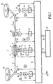
- 1 denotes a rotating scanning device with a fixed upper drum 2 and a fixed lower drum 3.
- a crown wheel disc (not shown) rotates in the direction of an arrow 5 in a dividing joint 4.
- recording / playback magnetic heads which scan a magnetic tape 6 wound helically around the scanning device 1.
- the magnetic tape 6 is guided in the direction of an arrow 7 by two guide elements 8 and 9.
- the top wheel disc is set in rotation by a top wheel motor 11 via a drive shaft 10.
- the drive shaft 10 carries a speedometer dial 12 for determining the rotational phase by means of a sensor 13 directed at the speedometer dial 12.
- the tacho signal which is taken from the speedometer disk 12 by the sensor 13, is fed to a drive control / regulation 14, which generates a control voltage for a head-wheel amplifier output stage 15 in the form of a target / actual comparison, in which the control signal is amplified accordingly in order to track the downstream top wheel motor 11.
- the actual signal required for the target / actual comparison is derived from a reference signal fed to a terminal 16 of the drive control / regulation.
- the feed speed of the magnetic tape 6 in the direction of the arrow 7 determines a capstan shaft 17 which is in engagement with the magnetic tape 6 and against which the magnetic tape 6 is pressed by a pressure roller 18.
- the capstan shaft 17 is driven by a capstan motor 19.
- the feed rate is determined by reading a control track recorded on the magnetic tape 6 with a magnetic head 20.
- the control track pulses read from the control track are fed to the drive controller 14 so that in a further target / actual comparison a control voltage for the capstan amplifier output stage 21 can be derived, which in turn determines the speed and direction of rotation of the capstan motor 19.
- the feed speed and the feed direction of the magnetic tape 6 are specified by an operator of the magnetic tape device, in which e.g. a certain playback or recording mode is selected by pressing a specific button arranged on a control panel 22.
- the control panel 22 is connected to the drive controller 14 via a data bus 23, so that the selected operating mode can be transmitted in the form of commands and data.
- the drive controller 14 provides data to the control panel 22 via a further data bus 24 in order to acknowledge the current setting of the drive.
- the query and control of the control panel 23 is usually processor-controlled. This processor control is independent of that of the individual servos.
- the magnetic tape device has two tape winding servos III and IV for regulating the tape tension on an unwinding spool 25 and on a winding spool 26.
- the tape tension on the unwind spool 25 is measured with a tape tension lever 27.
- the tape tension sensor lever 27 consists of a pivotable sensor lever arm, at one end of which a roller is attached, which engages with the magnetic tape 6.
- the other end of the pivoting feeler arm is scanned with a sensor to detect a derive the appropriate tape tension signal in accordance with the respective deflection of the feeler arm.
- Arrangements for measuring the tape tension of a magnetic tape are known per se (EP 0 186 591 A2).
- the tape tension signal (actual value) generated by the tape tension lever 27 is compared in the drive control 14 with a tape tension setpoint.
- the drive control / regulation 14 emits an actuating signal to a winding amplifier output stage 28 which controls the torque of a winding motor 29 which is coupled to the unwinding spool 25 in a rotationally fixed manner.
- the respective direction of rotation and axis position of the winding motor 29 is determined by scanning a speedometer disk 30 with sensor elements 31.
- the speedometer disk 30 is rigidly coupled to the axis of the winding motor 29.
- the tacho pulses emitted by the sensor elements 31 are evaluated in the drive control / regulation 14, for example in order to calculate the winding diameters of the tape windings 25 and 26 or to determine irregular operating states, such as the presence of a tape lot.
- the tape winding servo IV for regulating the tape tension on the take-up reel 26 corresponds to that for the unwinding reel 25.
- the actual value of the tape tension is measured again with a tape tension lever 32 and compared in the drive control 14 with a predetermined setpoint of the tape tension .
- the derived control voltage is amplified in a winding amplifier output stage 33 and passed on to a winding motor 34.
- the direction of rotation and axis position of the winding motor 34 is determined with a speedometer disk 35 and associated sensor elements 36.
- FIG. 2 shows a block diagram of the drive control / regulation 14 indicated in FIG. 1.
- the system control of the magnetic tape device which also includes the control panel 22, is designated by 37.
- the system control 37 also includes controls that do not directly affect the head-wheel servo I, the capstan servo II, the unwinding servo III and the rewinding servo IV.
- a first microprocessor 38 has a monitoring function: it monitors, for example, the circuits and sensors of servos I to IV.
- data which are generated in a second subordinate microprocessor 39 and are required for calculating manipulated variables are monitored.
- the first microprocessor 38 monitors the individual servos I to IV with regard to their function, ie whether the manipulated variables calculated by the second subordinate microprocessor 39 are plausible in terms of their range of values based on measured control variables, ie whether they represent valid data or not. Furthermore, the first microprocessor 38 calculates the tape position present in a magnetic tape cassette in order to determine the remaining playing time or to cause the winding speed at the beginning or end of the tape to be limited by the second microprocessor 39 in the case of a fast forward or rewind of the magnetic tape 6. In addition, the first superordinate microprocessor 38 specifies the control loop operating mode of the individual servos I to IV, for example whether the head-wheel servo I is to be operated with or without a phase controller.
- the first microprocessor 38 sets the tape speed as a function of time, e.g. in the event of a change from fast forward to stop, not an abrupt, but a gradual, ramp-like change in the winding speed of the magnetic tape 6 by the two winding servos III and IV.
- the commands and data issued by the first microprocessor 38 are fed to the second subordinate microprocessor 39 via a data bus 40.
- This second subordinate microprocessor 39 of type 80C196 internally has a timer 41 and an A / D converter 42.
- the second microprocessor 39 is clocked by an 8 MHz clock signal at a terminal 43.
- the timer 41 of the second microprocessor 39 is used to synchronize the second microprocessor 39 44 several reference signals are supplied, for example a vertical synchronizing signal 2V, a control track signal CTR and a clock signal CLK.
- the strip tension signals of the strip tension sensing levers 27 and 32 described in connection with FIG. 1 are fed from the winding servos III and IV inputs of the internal A / D converter 42.
- a timer 45 converts the tacho pulses (FIG. 1) emitted by sensors 13, 31 and 36 into corresponding digital values; The same also applies to the control track pulses CTR emitted by the control track head 20.
- the timer 45 is supplied with a 9 MHz clock signal (terminal 46) and a 300 Hz signal (terminal 47) as a reference.
- the timer 45 consists of a series of gates and counters which count the number of clock pulses between successive tacho or control track pulses.
- a counting result actual value
- the timer 45 emits an interrupt signal to the second microprocessor 39, so that the counting results determined can be adopted by the second microprocessor 39 as 8-bit data words.
- the second microprocessor 39 calculates a digital manipulated variable assigned to the individual head gear servos on the basis of the digital values of the actual values determined and the target values specified by the first superordinate microprocessor 38 according to certain control algorithms.
- the calculated digital control values - word-alternating with respect to the individual servos I to IV - arrive via a bidirectional data bus 48 to the inputs of a D / A converter 49, which converts the applied digital control values into corresponding analog control values.
- the analog control values at the output of the D / A converter 49 are subsequently divided into 4 channels in a demultiplexer 50 and, after a corresponding intermediate storage in a sample and hold circuit 51, are fed to the correspondingly assigned servos 38 to 41.
- the demultiplexer 50 and the sample and hold circuit 51 are controlled by digital signals of a 4 bit wide data bus 52 which branches off from the 16 bit wide data bus 48.
- the second subordinate microprocessor 39 calculates only the relevant setting values for the servos I to IV, the gain, time constants and set division factors being taken into account in the timer 45. Since in the case of the winding servos III and IV the masses of the tape reels are also included in the control behavior, the winding diameter of the unwinding spool 25 and the winding reel 26 is determined in order to adapt the control behavior accordingly. The winding diameter of the windings 25 and 26 is calculated on the basis of the pulse signals output by the sensors 31 and 36.
- a speed limitation of the winding motors 29 and 34 is integrated in order to prevent tearing of the magnetic tape 6 in irregular operating conditions, such as sticking of the magnetic tape 6 to one of the tape guide elements due to increased air humidity. Furthermore, the second microprocessor 39 takes over the calculation of digital manipulated variables for speed and phase control of the head wheel.
- phase control e.g. 8 V sync signals, 2 V sync signals and 300 Hz control track reference signals.
- the values of the control signals generated by the timer 45 and evaluated by the second subordinate microprocessor 39 are also fed via a bus 53 to the first superordinate microprocessor 38 for monitoring and diagnosis. Via the bus 53, measurement data also arrive via the respective deflection of the belt tension lever. As mentioned at the beginning, however, this data is only used to monitor the operating state of the magnetic tape device and to derive corresponding specifications for the second subordinate microprocessor, and not, for example, digital control values.
- the recording / reproducing magnetic heads are attached to the periphery of a rotating head wheel.
- a rotating (upper) drum which carries the recording / reproducing magnetic heads, for scanning the magnetic tape 6 instead of a rotating head wheel.
- the (upper) drum is driven by the motor 11.
Landscapes
- Engineering & Computer Science (AREA)
- Computer Hardware Design (AREA)
- Adjustment Of The Magnetic Head Position Track Following On Tapes (AREA)
- Control Of Multiple Motors (AREA)
- Controlling Rewinding, Feeding, Winding, Or Abnormalities Of Webs (AREA)
Claims (10)
- Dispositif de commande et de réglage d'un magnétophone à cassette avec- un servomécanisme des têtes pour le réglage de la vitesse de rotation et de la position de phase d'un disque à têtes d'un dispositif de balayage rotatif;- un servomécanisme de cabestan pour le réglage de la vitesse de transport d'une bande magnétique;- un premier servomécanisme de bobinage de bande pour le réglage de la tension de la bande à hauteur d'une bobine débitrice de la bande magnétique;- un deuxième servomécanisme de bobinage de bande pour le réglage de la tension de la bande à hauteur d'une bobine réceptrice de la bande magnétique, ainsi- qu'un dispositif commandé par microprocesseur pour la commande et le réglage du servomécanisme, caractérisé en cequ'au dispositif commandé par microprocesseur en vue de la commande et du réglage du servomécanisme sont affectés un premier et un deuxième microprocesseur (38, 39), le premier microprocesseur (38) définissant un type de réglage déterminé pour les différents servomécanismes (I à IV) et contrôlant l'état de fonctionnement respectif des servomécanismes individuels (I à IV) et le deuxième microprocesseur (39) calculant en fonction du type de réglage prédéterminé par le premier microprocesseur (38) des grandeurs de réglage numériques en vue du réglage des servomécanismes individuels (I à IV) à l'aide des grandeurs de réglage affectées aux servomécanismes (I à IV).
- Dispositif selon la revendication 1, caractérisé en ce que les différents servomécanismes (I à IV) sont commandés au passage d'un type de réglage déterminé à un autre type de réglage déterminé par le premier microprocesseur (38), de telle sorte que l'adaptation au type de réglage modifié se déroule en souplesse.
- Dispositif selon la revendication 2, caractérisé en ce qu'en cas de modification de la valeur prédéterminée pour le servomécanisme de cabestan (II), la vitesse de transport de la bande magnétique (6) jusqu'à présent est adaptée en souplesse à une nouvelle vitesse de transport.
- Dispositif selon la revendication 1, caractérisé en ce que le premier microprocesseur (38) est prévu pour le calcul du temps de lecture résiduel sur la bande magnétique (6) à partir des valeurs numériques des signaux tachymétriques qui sont produits par les générateurs tachymétriques des moteurs (29, 34) en vue de l'entraînement des bobines débitrice et réceptrice (25, 26).
- Dispositif selon la revendication 4, caractérisé en ce que le premier microprocesseur (38) est prévu pour la limitation de la vitesse de la bande à une entrée et à une sortie de la bande magnétique (6) pour amener une valeur de consigne prédéterminée au deuxième microprocesseur (39).
- Dispositif selon la revendication 1, caractérisé en ce que le premier microprocesseur est prévu pour le contrôle des signaux dans les différents servomécanismes (I à IV).
- Dispositif selon la revendication 1, caractérisé en ce que le deuxième microprocesseur (39) est prévu pour le calcul des valeurs numériques des grandeurs de réglage pour les servomécanismes individuels (I à IV) à partir des grandeurs de réglage des servomécanismes individuels (I à IV),- en ce qu'un convertisseur N/A est prévu pour la conversion des valeurs numériques calculées en grandeurs de réglage analogiques, et- en ce que les grandeurs de réglage analogiques obtenues commandent des circuits de réglage (11, 15; 19, 21; 28; 29; 33, 34) des servomécanismes individuels (I à IV).
- Dispositif selon la revendication 7, caractérisé en ce que les circuits de réglage (11, 15; 19, 21; 28, 29; 33, 34) des servomécanismes individuels (I à IV) comprennent des étages finaux amplificateurs de moteur (15, 21, 28, 33) pour commander les moteurs (11, 19, 28, 34).
- Dispositif selon la revendication 1, caractérisé en ce que le deuxième microprocesseur (39) est prévu pour le calcul des valeurs de réglage pour les servomécanismes (I à IV).
- Dispositif selon la revendication 1, caractérisé en ce que le deuxième microprocesseur (39) est prévu pour le calcul de- valeurs numériques d'un signal de réglage en vue du réglage de la vitesse et de la phase du servomécanisme des têtes (I),- valeurs numériques d'un signal de réglage pour le réglage de la vitesse du servomécanisme de cabestan (II), et- valeurs numériques d'un signal de réglage pour le réglage de la tension de la bande du servomécanisme débiteur (III) et du servomécanisme récepteur (IV).
Applications Claiming Priority (2)
| Application Number | Priority Date | Filing Date | Title |
|---|---|---|---|
| DE4129593A DE4129593A1 (de) | 1991-09-06 | 1991-09-06 | Verfahren zur steuerung und regelung eines magnetbandgeraetes |
| DE4129593 | 1991-09-06 |
Publications (2)
| Publication Number | Publication Date |
|---|---|
| EP0532092A1 EP0532092A1 (fr) | 1993-03-17 |
| EP0532092B1 true EP0532092B1 (fr) | 1996-08-28 |
Family
ID=6439964
Family Applications (1)
| Application Number | Title | Priority Date | Filing Date |
|---|---|---|---|
| EP92202665A Expired - Lifetime EP0532092B1 (fr) | 1991-09-06 | 1992-09-03 | Dispositif de commande et de régulation d'un appareil à bande magnétique |
Country Status (4)
| Country | Link |
|---|---|
| EP (1) | EP0532092B1 (fr) |
| JP (1) | JPH05198052A (fr) |
| AT (1) | ATE142042T1 (fr) |
| DE (2) | DE4129593A1 (fr) |
Family Cites Families (5)
| Publication number | Priority date | Publication date | Assignee | Title |
|---|---|---|---|---|
| US4536806A (en) * | 1982-04-02 | 1985-08-20 | Ampex Corporation | Microprocessor controlled multiple servo system for a recording and/or reproducing apparatus |
| DE3382456D1 (de) * | 1982-04-02 | 1991-12-12 | Ampex | Spulenservosystem in einem aufzeichnungs- und/oder wiedergabegeraet. |
| AT376860B (de) * | 1983-03-15 | 1985-01-10 | Philips Nv | System zum wiedergeben von auf einem magnetband gespeicherten informationssignalen |
| DE3324482A1 (de) * | 1983-07-07 | 1985-01-24 | Miele & Cie GmbH & Co, 4830 Gütersloh | Mikrocomputergesteuertes programmschaltwerk fuer haushaltsgeraete |
| US4794472A (en) * | 1985-07-30 | 1988-12-27 | Matsushita Electric Industrial Co., Ltd. | Video tape reproducing apparatus with a processor that time-shares different operations |
-
1991
- 1991-09-06 DE DE4129593A patent/DE4129593A1/de not_active Withdrawn
-
1992
- 1992-09-03 EP EP92202665A patent/EP0532092B1/fr not_active Expired - Lifetime
- 1992-09-03 DE DE59206992T patent/DE59206992D1/de not_active Expired - Fee Related
- 1992-09-03 AT AT92202665T patent/ATE142042T1/de not_active IP Right Cessation
- 1992-09-03 JP JP4235853A patent/JPH05198052A/ja active Pending
Also Published As
| Publication number | Publication date |
|---|---|
| DE59206992D1 (de) | 1996-10-02 |
| DE4129593A1 (de) | 1993-03-11 |
| JPH05198052A (ja) | 1993-08-06 |
| ATE142042T1 (de) | 1996-09-15 |
| EP0532092A1 (fr) | 1993-03-17 |
Similar Documents
| Publication | Publication Date | Title |
|---|---|---|
| DE2313024C3 (de) | Anordnung zur Feststellung des sich nähernden Endes eines von einer ersten Speicherspule abgespulten Magnetbandes beim Umspulen von der ersten auf eine zweite Speicherspule bei einem Magnetbandgerät | |
| DE3318324C2 (fr) | ||
| DE3032506C2 (fr) | ||
| DE3634662C2 (fr) | ||
| DE3852509T2 (de) | Bandplatzauffindungsgerät mit Startsteuerfunktion. | |
| DE3048880C2 (fr) | ||
| DE3779944T2 (de) | Vorrichtung zur ladung eines bandes. | |
| DE2711951C2 (de) | Frequenz-Gleichspannungsumsetzer im Istwert-Zweig einer Drehzahlregelschaltung eines Antriebs | |
| DE3212711C2 (de) | Schaltungsanordnung zum Steuern eines Bahntransportsystems | |
| DE3132839C2 (de) | Vorrichtung zur Abschaltung des Bandantriebs bei Erreichen des Bandendes in einem Magnetbandgerät | |
| DE2533512B2 (de) | Einrichtung zur Voreinstellung der Spurlage des Dreh-Magnetkopfes und der Abfühlverstärkung eines Magnetbandgerätes | |
| EP0532092B1 (fr) | Dispositif de commande et de régulation d'un appareil à bande magnétique | |
| DE3818360A1 (de) | Verfahren und geraet zum steuern eines bandtransportes von spule zu spule | |
| DE69025490T2 (de) | Servosystem für die Bandspannung eines Videobandaufzeichnungs- und/oder -wiedergabegerätes | |
| DE1909429B2 (de) | Verfahren zur optimierung der banderregung bei magnetband geraeten mit rotierenden koepfen und geraet zur durchfueh rung des verfahrens | |
| DE69322915T2 (de) | Aufnahme- und/oder Wiedergabegerät ohne Kapstan und Andruckrolle sowie Verfahren zur Steuerung desselben | |
| DE3412735C2 (fr) | ||
| DE2740831C2 (de) | Servoeinrichtung für die Regelung des Antriebes der Bandauflaufspule eines Magnetbandgerätes | |
| DE3152952C2 (fr) | ||
| EP0303921A1 (fr) | Dispositif d'élévation pour un rotor | |
| EP0063646B1 (fr) | Procédé et dipositif pour la détermination et l'indication du temps de déroulement écoulé ou du temps de déroulement restant de cassettes ou de bobines pour supports d'enregistrements sous forme de bande | |
| DE2254901C2 (de) | Servoeinrichtung für die Regelung der Antriebsgeschwindigkeit der Bandwickelrollen eines Magnetbandgerätes | |
| DE69019209T2 (de) | Bandgeschwindigkeitsartdiskriminierungssystem. | |
| DE3810288A1 (de) | Motordrehzahl-regelvorrichtung | |
| DE19537891A1 (de) | Magnetisches Aufzeichnungs- und Wiedergabegerät, eingerichtet zur Einsparung der elektrischen Energie, die beim Erfassen des Bandendes verbraucht wird, und zur Verringerung der Belastung des Mikroprozessors |
Legal Events
| Date | Code | Title | Description |
|---|---|---|---|
| PUAI | Public reference made under article 153(3) epc to a published international application that has entered the european phase |
Free format text: ORIGINAL CODE: 0009012 |
|
| AK | Designated contracting states |
Kind code of ref document: A1 Designated state(s): AT DE FR GB |
|
| 17P | Request for examination filed |
Effective date: 19930827 |
|
| 17Q | First examination report despatched |
Effective date: 19941010 |
|
| GRAH | Despatch of communication of intention to grant a patent |
Free format text: ORIGINAL CODE: EPIDOS IGRA |
|
| GRAH | Despatch of communication of intention to grant a patent |
Free format text: ORIGINAL CODE: EPIDOS IGRA |
|
| GRAA | (expected) grant |
Free format text: ORIGINAL CODE: 0009210 |
|
| AK | Designated contracting states |
Kind code of ref document: B1 Designated state(s): AT DE FR GB |
|
| REF | Corresponds to: |
Ref document number: 142042 Country of ref document: AT Date of ref document: 19960915 Kind code of ref document: T |
|
| PG25 | Lapsed in a contracting state [announced via postgrant information from national office to epo] |
Ref country code: AT Effective date: 19960903 |
|
| REF | Corresponds to: |
Ref document number: 59206992 Country of ref document: DE Date of ref document: 19961002 |
|
| GBT | Gb: translation of ep patent filed (gb section 77(6)(a)/1977) |
Effective date: 19961113 |
|
| ET | Fr: translation filed | ||
| PLBE | No opposition filed within time limit |
Free format text: ORIGINAL CODE: 0009261 |
|
| 26N | No opposition filed | ||
| PGFP | Annual fee paid to national office [announced via postgrant information from national office to epo] |
Ref country code: GB Payment date: 19970829 Year of fee payment: 6 |
|
| PGFP | Annual fee paid to national office [announced via postgrant information from national office to epo] |
Ref country code: FR Payment date: 19970923 Year of fee payment: 6 |
|
| PGFP | Annual fee paid to national office [announced via postgrant information from national office to epo] |
Ref country code: DE Payment date: 19971121 Year of fee payment: 6 |
|
| PG25 | Lapsed in a contracting state [announced via postgrant information from national office to epo] |
Ref country code: GB Free format text: LAPSE BECAUSE OF NON-PAYMENT OF DUE FEES Effective date: 19980903 |
|
| REG | Reference to a national code |
Ref country code: FR Ref legal event code: CD |
|
| GBPC | Gb: european patent ceased through non-payment of renewal fee |
Effective date: 19980903 |
|
| PG25 | Lapsed in a contracting state [announced via postgrant information from national office to epo] |
Ref country code: FR Free format text: LAPSE BECAUSE OF NON-PAYMENT OF DUE FEES Effective date: 19990531 |
|
| PG25 | Lapsed in a contracting state [announced via postgrant information from national office to epo] |
Ref country code: DE Free format text: LAPSE BECAUSE OF NON-PAYMENT OF DUE FEES Effective date: 19990701 |
|
| REG | Reference to a national code |
Ref country code: FR Ref legal event code: ST |