EP0532278A2 - Verfahren zum Aufzeichnen von Informationen auf einer Videoplatte - Google Patents
Verfahren zum Aufzeichnen von Informationen auf einer Videoplatte Download PDFInfo
- Publication number
- EP0532278A2 EP0532278A2 EP92308155A EP92308155A EP0532278A2 EP 0532278 A2 EP0532278 A2 EP 0532278A2 EP 92308155 A EP92308155 A EP 92308155A EP 92308155 A EP92308155 A EP 92308155A EP 0532278 A2 EP0532278 A2 EP 0532278A2
- Authority
- EP
- European Patent Office
- Prior art keywords
- signal
- code
- disk
- video
- data
- Prior art date
- Legal status (The legal status is an assumption and is not a legal conclusion. Google has not performed a legal analysis and makes no representation as to the accuracy of the status listed.)
- Withdrawn
Links
Images









Classifications
-
- G—PHYSICS
- G11—INFORMATION STORAGE
- G11B—INFORMATION STORAGE BASED ON RELATIVE MOVEMENT BETWEEN RECORD CARRIER AND TRANSDUCER
- G11B27/00—Editing; Indexing; Addressing; Timing or synchronising; Monitoring; Measuring tape travel
- G11B27/10—Indexing; Addressing; Timing or synchronising; Measuring tape travel
- G11B27/19—Indexing; Addressing; Timing or synchronising; Measuring tape travel by using information detectable on the record carrier
- G11B27/28—Indexing; Addressing; Timing or synchronising; Measuring tape travel by using information detectable on the record carrier by using information signals recorded by the same method as the main recording
- G11B27/30—Indexing; Addressing; Timing or synchronising; Measuring tape travel by using information detectable on the record carrier by using information signals recorded by the same method as the main recording on the same track as the main recording
- G11B27/3027—Indexing; Addressing; Timing or synchronising; Measuring tape travel by using information detectable on the record carrier by using information signals recorded by the same method as the main recording on the same track as the main recording used signal is digitally coded
-
- G—PHYSICS
- G11—INFORMATION STORAGE
- G11B—INFORMATION STORAGE BASED ON RELATIVE MOVEMENT BETWEEN RECORD CARRIER AND TRANSDUCER
- G11B19/00—Driving, starting, stopping record carriers not specifically of filamentary or web form, or of supports therefor; Control thereof; Control of operating function ; Driving both disc and head
- G11B19/02—Control of operating function, e.g. switching from recording to reproducing
- G11B19/12—Control of operating function, e.g. switching from recording to reproducing by sensing distinguishing features of or on records, e.g. diameter end mark
-
- G—PHYSICS
- G11—INFORMATION STORAGE
- G11B—INFORMATION STORAGE BASED ON RELATIVE MOVEMENT BETWEEN RECORD CARRIER AND TRANSDUCER
- G11B27/00—Editing; Indexing; Addressing; Timing or synchronising; Monitoring; Measuring tape travel
- G11B27/02—Editing, e.g. varying the order of information signals recorded on, or reproduced from, record carriers
- G11B27/031—Electronic editing of digitised analogue information signals, e.g. audio or video signals
- G11B27/034—Electronic editing of digitised analogue information signals, e.g. audio or video signals on discs
-
- G—PHYSICS
- G11—INFORMATION STORAGE
- G11B—INFORMATION STORAGE BASED ON RELATIVE MOVEMENT BETWEEN RECORD CARRIER AND TRANSDUCER
- G11B27/00—Editing; Indexing; Addressing; Timing or synchronising; Monitoring; Measuring tape travel
- G11B27/10—Indexing; Addressing; Timing or synchronising; Measuring tape travel
- G11B27/102—Programmed access in sequence to addressed parts of tracks of operating record carriers
- G11B27/105—Programmed access in sequence to addressed parts of tracks of operating record carriers of operating discs
-
- G—PHYSICS
- G11—INFORMATION STORAGE
- G11B—INFORMATION STORAGE BASED ON RELATIVE MOVEMENT BETWEEN RECORD CARRIER AND TRANSDUCER
- G11B27/00—Editing; Indexing; Addressing; Timing or synchronising; Monitoring; Measuring tape travel
- G11B27/10—Indexing; Addressing; Timing or synchronising; Measuring tape travel
- G11B27/19—Indexing; Addressing; Timing or synchronising; Measuring tape travel by using information detectable on the record carrier
- G11B27/28—Indexing; Addressing; Timing or synchronising; Measuring tape travel by using information detectable on the record carrier by using information signals recorded by the same method as the main recording
- G11B27/30—Indexing; Addressing; Timing or synchronising; Measuring tape travel by using information detectable on the record carrier by using information signals recorded by the same method as the main recording on the same track as the main recording
- G11B27/309—Table of contents
-
- G—PHYSICS
- G11—INFORMATION STORAGE
- G11B—INFORMATION STORAGE BASED ON RELATIVE MOVEMENT BETWEEN RECORD CARRIER AND TRANSDUCER
- G11B27/00—Editing; Indexing; Addressing; Timing or synchronising; Monitoring; Measuring tape travel
- G11B27/10—Indexing; Addressing; Timing or synchronising; Measuring tape travel
- G11B27/19—Indexing; Addressing; Timing or synchronising; Measuring tape travel by using information detectable on the record carrier
- G11B27/28—Indexing; Addressing; Timing or synchronising; Measuring tape travel by using information detectable on the record carrier by using information signals recorded by the same method as the main recording
- G11B27/32—Indexing; Addressing; Timing or synchronising; Measuring tape travel by using information detectable on the record carrier by using information signals recorded by the same method as the main recording on separate auxiliary tracks of the same or an auxiliary record carrier
- G11B27/327—Table of contents
- G11B27/329—Table of contents on a disc [VTOC]
-
- H—ELECTRICITY
- H04—ELECTRIC COMMUNICATION TECHNIQUE
- H04N—PICTORIAL COMMUNICATION, e.g. TELEVISION
- H04N9/00—Details of colour television systems
- H04N9/79—Processing of colour television signals in connection with recording
- H04N9/80—Transformation of the television signal for recording, e.g. modulation, frequency changing; Inverse transformation for playback
- H04N9/82—Transformation of the television signal for recording, e.g. modulation, frequency changing; Inverse transformation for playback the individual colour picture signal components being recorded simultaneously only
- H04N9/8205—Transformation of the television signal for recording, e.g. modulation, frequency changing; Inverse transformation for playback the individual colour picture signal components being recorded simultaneously only involving the multiplexing of an additional signal and the colour video signal
- H04N9/8233—Transformation of the television signal for recording, e.g. modulation, frequency changing; Inverse transformation for playback the individual colour picture signal components being recorded simultaneously only involving the multiplexing of an additional signal and the colour video signal the additional signal being a character code signal
-
- G—PHYSICS
- G11—INFORMATION STORAGE
- G11B—INFORMATION STORAGE BASED ON RELATIVE MOVEMENT BETWEEN RECORD CARRIER AND TRANSDUCER
- G11B2220/00—Record carriers by type
- G11B2220/20—Disc-shaped record carriers
-
- G—PHYSICS
- G11—INFORMATION STORAGE
- G11B—INFORMATION STORAGE BASED ON RELATIVE MOVEMENT BETWEEN RECORD CARRIER AND TRANSDUCER
- G11B2220/00—Record carriers by type
- G11B2220/20—Disc-shaped record carriers
- G11B2220/25—Disc-shaped record carriers characterised in that the disc is based on a specific recording technology
- G11B2220/2537—Optical discs
- G11B2220/2587—Laser Discs; Optical disc using analog recording
-
- H—ELECTRICITY
- H04—ELECTRIC COMMUNICATION TECHNIQUE
- H04N—PICTORIAL COMMUNICATION, e.g. TELEVISION
- H04N9/00—Details of colour television systems
- H04N9/79—Processing of colour television signals in connection with recording
- H04N9/797—Processing of colour television signals in connection with recording for recording the signal in a plurality of channels, the bandwidth of each channel being less than the bandwidth of the signal
Definitions
- the present invention generally relates to a method of recording information on a video disk, such as a LD (Laser Disk), and more particularly to a method of recording TOC (Table-Of-Contents) information in the recording of a MUSE (Multiple Sub-Nyquist Sampling Encoding) signal.
- a video disk such as a LD (Laser Disk)
- TOC Table-Of-Contents
- MUSE Multiple Sub-Nyquist Sampling Encoding
- the high-vision broadcasting is capable of transmitting high-definition television signals, and is quite different from the conventional NTSC system.
- a high-vision signal is transmitted to users by utilizing a BS (Broadcasting Satellite).
- the high-vision signal needs a transmission band approximately equal to or larger than five times the transmission bands of the existing television broadcasting systems. Hence, if the high-vision signal is transmitted without any processing, it is impossible to transmit the high-vision signal within a band width equal to one channel of the BS.
- the above is an outline of the high-vision broadcasting and MUSE system. It is possible to apply the above technique to the recording or reproducing of video signals for video disks, such as laser disks, as in the case of the conventional NTSC system. That is, analog MUSE signals are recorded on video disks.
- the MUSE system has an undefined line, which is a line having a horizontal scanning period number (hereinafter, referred to as a line number) "564" in case that the MUSE system is applied to the video disk recording.
- the undefined line is used as a program transmission control signal, while this is not needed in a non-broadcasting system. That is, the No. 564 line is a "free" line in the video disk recording.
- the predetermined data is, for example, data for controlling a video disk player, and data for reproduction control, such as address data related to information recorded on a video disk.
- the predetermined data as described above is referred to as a disk code DSCD.
- table-of-contents information (hereinafter simply referred to as TOC data or information) concerning the address of information recorded on the video disk is not recorded thereon.
- TOC data or information table-of-contents information
- desired information is searched for using a frame number inserted into a program area, or using a chapter number inserted therein if the chapter number is recorded on the video disk, which requires rather complicated system structure and in which the search can be enabled rather slowly.
- the above object of the present invention can be achieved by a method of recording information on a video disk, including the steps of: recording a video signal on the video disk; and recording table-of-contents data to control reproduction of the recorded video signal, on a plurality of frames in a lead-in area of the video disk.
- the table-of-contents data has a data structure, which is completed in each of the plurality of frames and is repeatedly identical in each of the plurality of frames adjacent to each other.
- the controllability and operationability of the video disk players can be improved by use of the table-of-contents data.
- the identical table-of-contents data is repeatedly recorded over a plurality of adjacent frames, and has a data structure completed in each frame, the management of the table-of-contents data can be performed by a unit block, so that the signal processing by use of a microcomputer can be easily executed, and that, in case of a dropout in the reproduction operation, the re-reading of the table-of-contents data can be easily and speedily enabled by jumping-back with respect to just each frame unit.
- the video signal is a MUSE signal and the table-of-contents data is recorded on the video signal area of the MUSE signal, for example at the line No.47 to 562 and/or No.608 to 1124.
- the table-of-contents data since the table-of-contents data is recorded in the video signal area other than the frame pulse and control signal areas, which are necessary for the reproduction of the MUSE signal, the table-of-contents data can improve the controllability and operationability of the video disk player without interrupting the operation of a MUSE decoder in the reproduction operation.
- FIG. 1 shows an overview of a MUSE signal recording system (video signal system) to which the present invention is applied.
- a high-vision signal HV to be recorded is inputted to a MUSE encoder ENC, which includes a sub-sample encoder 1, a disk code inserting circuit 2, a disk code generating circuit 3, and an output circuit 4.
- the high-vision signal HV has R, G and B signal components.
- the sub-sample encoder 1 converts the high-vision signal into a digital signal and encodes the digital signal into a digital MUSE signal A by a multiple sub-sampling method.
- the disk code inserting circuit 2 inserts the disk code DSCD into a free line FL (an undefined horizontal line having line number 564; explained later in detail) in each video frame of the digital MUSE signal A outputted from the sub-sample encoder 1.
- the disk code generating circuit 3 supplies the disk code DSCD to the disk code inserting circuit 2.
- the output circuit 4 carries out a filtering process for a multiplexed MUSE signal B outputted from the disk code inserting circuit 2, and then converts a filtered signal into an analog signal. In this manner, an analog MUSE signal C is outputted by the output circuit 4.
- the analog MUSE signal C is outputted to an FM (Frequency Modulation) circuit 5, which frequency-modulates the analog MUSE signal C.
- An FM signal D outputted from the FM circuit 5 is applied to an original disk recording apparatus 6.
- An original disk 7 has recording surfaces and photoresist films respectively coated thereon.
- the original disk recording apparatus 6 projects a light beam modulated by the FM signal D onto the original disk 7, and hence signal pits are recorded on the recording surfaces.
- the analog MUSE signal which has been frequency-modulated is recorded on the original disk 7.
- the disk code DSCD has been inserted into the free line FL of each video frame in the analog MUSE signal.
- a process for producing a large number of video disks from the original disk 7 do not directly relate to the present invention, and a description thereof will be omitted here.
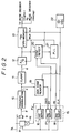
- FIG. 2 shows an overview of a driving control system for a spindle motor and a read signal processing system in a video disk player of an optical MUSE system.
- the reason why the reproduction system of the MUSE signal is utilized here, is that the present invention has an advantage during an operation in which the disk code DSCD is read and the video disk player is controlled based on the readout disk code DSCD.
- a spindle servo circuit 15 has a three-stage servo system, which gradually increases precision of the adjustment of the rotation velocity of the spindle motor 8 in accordance with increase in the rotating condition and which finally rotates the spindle motor 8 in synchronism with the horizontal synchronizing signal HD.
- the rotation velocity of the spindle motor 8 is roughly adjusted in a first (initial) adjustment stage, and is finely adjusted in the second adjustment, and then, the synchronization is achieved in the third adjustment stage.
- the spindle servo circuit 15 is provided with a first servo circuit 16, a second servo circuit 17 and a third servo circuit 18.
- the first servo circuit 16 roughly adjusts the rotation velocity of the spindle motor 8 immediately after it is started.
- the first servo circuit 16 compares the frequency of a reference pulse signal generated by a built-in reference pulse generator with the frequency of a rotation velocity signal FV generated by a rotation velocity detector 14 attached to the spindle motor 8, and controls the rotation velocity of the spindle motor 8 with a precision which mainly depends on a precision of the rotation velocity detector 14.
- a pickup 9 optically reads information (signal pits) recorded on the video disk 7A and converts optical information into an electric signal.
- This electric signal is applied, as a reproduced RF signal d, to a frequency demodulation circuit 10.
- the FM demodulation circuit 10 frequency-demodulates the reproduced RF signal d (frequency modulated signal) to thereby generate an original MUSE signal c.
- the demodulated original MUSE signal c is applied to a clamp circuit 11 and a disk code reader 19.
- the demodulated original MUSE signal c is processed by means of the clamp circuit 11, an A/D converter 12 and a TBC (Time Base Corrector) 13 which has a FIFO (First In First Out) memory, and is then applied to a MUSE decoder. At this time, the rotation velocity of the spindle motor 8 has not yet been regulated at the defined rotation velocity, and hence the original MUSE signal C will have an error.
- TBC Time Base Corrector
- the disk code DSCD is read by the disk code reader 19, to which a clock signal CLK is inputted from an oscillator 22, and used for controlling rotation velocity control by the second servo circuit 17.
- the second servo circuit 17 receives the disk code DSCD from the disk code reader 19 and a frame pulse FP from a synchronization detection circuit 20, and controls the single motor 8 so that the disk code DSCD and the frame pulse FP are respectively reproduced at reference times. That is, the servo control of the spindle motor 8 is switched from the rough adjustment by the first servo circuit 16 to the fine adjustment by the second servo circuit 17 when the rotation velocity of the spindle motor 8 has reached the reference value defined for the first servo circuit 16. By the fine adjustment by the second servo circuit 17, the frame pulse FP included in the MUSE signal can be detected by the synchronization detection circuit 20.
- a PLL (Phase Lock Loop) circuit 21 is provided between the synchronization detection circuit 20 and the TBC 13 to establish the phase lock loop by giving the WCK signal to the TBC 13 which is generated on the basis of the output signal of the synchronization detection circuit 20.
- the detected frame pulse FP is supplied from the synchronization detection circuit 20 to the second servo circuit 17.
- the frame pulse FP and the disk code DSCD are signals assigned for each frame in the MUSE signal.
- the second servo circuit 17 finely controls the rotation velocity of the spindle motor 8. The rotation velocity control by means of the second servo circuit 17 is carried out not only when the spindle motor 8 is activated but also when the rotation velocity of the spindle motor 8 temporarily becomes out of the prescribed rotation velocity.
- the spindle motor 8 is controlled so as to rotate at a velocity other than the prescribed rotation velocity for normal reproduction operation.
- the disk code DSCD is useful in detecting a reproduced signal time base. The details of a format of the disk code DSCD will be described later.
- the synchronization detection circuit 20 detects the horizontal synchronizing signal HD from the reproduced MUSE signal.
- the detected horizontal synchronizing signal HD is applied to the third servo circuit 18.
- the servo control of the spindle motor 8 is switched from the second servo circuit 17 to the third servo circuit 18. Thereafter, the rotation velocity of the spindle motor 8 is more finely controlled on the basis of the horizontal synchronizing signal HD by means of the third servo circuit 18.
- the reproduced RF signal d from the pickup 9 is frequency-demodulated by the frequency demodulation circuit 10, and the demodulated MUSE signal c is applied to the clamp circuit 11.
- the clamp circuit 11 clamps the signal of the predetermined line (line number 563) in the MUSE signal at a clamp level (a 128/256 level), so that a DC (Direct Current) component is reproduced.
- a MUSE signal a outputted from the clamp circuit 11 is converted into a digital signal by the A/D converter 12, and then the digital signal is applied to the time base corrector (TBC) 13.
- TBC 13 corrects fluctuations or jitters in the time base which arise from an eccentricity of the video disk 7A or the like. This time base correction is carried out by using the FIFO memory of the TBC 13.
- the present invention relates to a method of recording the disk code DSCD on the video disk, and thus a further description of the spindle servo control will be omitted.
- a more detailed description of the spindle servo control is described, for example in "DEVELOPMENT (2) OF OPTICAL MUSE TYPE VIDEO DISK SYSTEM: PLAYER", ITEC ′90, 9-7, Japanese Patent Application Number 01-180811, and so on.
- FIGS. 3, 4, 5 and 6 will be used in order to facilitate understanding the present invention.
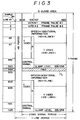
- FIG. 3 shows a transmission signal format of the MUSE signal
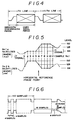
- FIG. 4 is a waveform diagram of the MUSE signal.
- FIG. 5 is a waveform diagram of the horizontal synchronizing signal HD
- FIG. 6 is a waveform diagram of the frame pulse (FP) line.
- STANDARD SYSTEM OF TRANSMISSION CONCERNING HIGH-DEFINITION TELEVISION BROADCASTING Ordinance No. 16 of Ministry of Postal Services, Article 8, Section 2, appended Figure 2, and so on.
- the MUSE signal has a frame consisting of two fields, and 1125 horizontal lines.
- Each of the lines includes the horizontal synchronizing signal HD located at the leading end thereof, and a subsequent video signal.
- the line having line Number 564 is used in the broadcasting system, and no definition is provided for the No. 564 line in the video disks.
- the disk code DSCD is inserted into this free line FL according to the present invention.
- the horizontal synchronizing signal HD is added to the MUSE signal within a level range identical to that of the video signal, and has an amplitude approximately half of a peak-to-peak value of the video signal.
- the HD signal waveform in the (i+1)th line is an inverted version of the HD signal waveform in the ith line.
- An HD signal waveform shown in FIG. 5 is reset (the horizontal synchronizing signal HD related to line number 3 rises) when the line inversion has been performed and the frame pulse FP has been sent.
- the levels related to samples No. 1 - 11 are arithmetic averages of the levels of two consecutive HD signal waveform samples.
- the level related to sample No. 1 is an arithmetic average of the levels of the immediately previous sample and the sample No. 2.
- the level related to sample No. 11 is an arithmetic average of the levels of the sample No.10 and the immediately behind sample.
- the MUSE signal consists of 480 sample values in one horizontal scanning period.
- FIG. 5 Figures shown in FIG. 5 as sample numbers represent sequential sample numbers from the first number in one horizontal scanning period.
- the time corresponding to the sample number 6 is a horizontal phase reference point, and is used for phase control of a clock generated for resampling of the MUSE signal in a decoder for decoding the MUSE signal.
- FIG. 5 Figures shown in FIG. 5 as levels represent levels of samples obtained by quantizing the MUSE signal into 256 levels.
- the level obtained at the horizontal phase reference point is a level of 128, and is a central value of the amplitude of the video signal.
- the MUSE signal has, together with the horizontal synchronizing signals HD, frame pulses FP which are respectively inserted, as a frame synchronizing signals, into the first and second lines.
- the waveform inversion of the horizontal synchronizing signals HD is reset by the respective frame pulses FP.
- FIG. 7 is a waveform diagram of the disk code DSCD.
- the disk code DSCD is generated by the disk code generating circuit 3 shown in FIG. 1, and is multiplexed, by means of the disk code inserting circuit 2, with the digital MUSE signal A from the sub-sample encoder 1.
- the free line FL having line number 564 in each frame is obtained during a multiplexing period within which the disk code DSCD is inserted into the MUSE signal A by means of the disk code inserting circuit 2. Examples of the multiplexing method will be described below:
- FIG.8 shows how the MUSE signal is sampled.
- FIG. 9 shows a format of the disk code DSCD.
- the disk code DSCD is inserted, as 76-bit data, within a period corresponding to sample Nos. 19 - 474 in the line having line number 564 shown in FIG. 8.
- the disk code DSCD includes, from the sample No. 19 side to the sample No. 474 side, a header SYNC, a control mode identification code MODE, a chapter address code CADR, a first frame address code FADR1, a second frame address code FADR2, and an error detection code CRCC.
- Header SYNC (FIG. 10)
- the header SYNC is a code for identifying a control signal for a read position of the pickup of the video disk player and for identifying an address signal.
- FIG. 10 shows an example of the format of the header SYNC.
- the header SYNC has identical contents except for the free line (undefined horizontal line) FL having line number 564 in each video frame in the lead-in area, a program area and a lead-out area on the video disk 7A, and a line for multiplexing the disk code DSCD other than No. 564 line in the lead-in area.
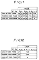
- the control mode identification code MODE includes information concerning attributes of the video disk to be reproduced, such as a video disk type and a video disk side, and information concerning a recording area on the video disk in which the disk code DSCD being considered is recorded. As shown in FIG. 11, the control mode identification code MODE has contents dependent on recording areas (thus, video frames corresponding to the recording areas). A description will now be given of the name and meaning of each bit in the control mode identification code MODE. PF: Multiplexing period identification bit
- the reason why the TOC presence identification bit TA is arranged in the disk code DSCD in the program video frame is as follows.
- the video disk player is activated in the program area. During this time, it is determined whether or not the TOC data has been recorded.
- the chapter address code CADR is a code showing the structure of a chapter of the video disk in which the disk code DSCD is recorded. As shown in FIG. 12, the chapter address code CADR has code contents different from each other for different recording areas. A description will now be given of the name and meaning of each bit in the chapter address code CADR.
- CF Chapter number code identification bit
- the first frame address code FADR1 includes a universal frame number code UFN in which continuous frame numbers are assigned to areas from the lead-in area to the lead-out area through the program area.
- the universal frame number code UFN is combined with an area identification code ADST indicating which area the universal frame number code UFN relates to.
- the bit allocation of the first frame address code FADR1 is such that the universal frame number code UFN is assigned to bits 0 - 16, and the area identification code ADST is assigned to bits 17 and 18.
- FIG. 14 shows an example of data of the universal frame number code UFN.
- a lead-in start address is "1FC21” in hexadecimal notation and a lead-in end address is "1FFFF” in hexadecimal notation when the lead-in area corresponds to 33 seconds.
- a program start address is "00000”
- a program end address is "1A5DF”.
- the address "1A5DF” indicates the number of frames when the program area amounts to one hour, and corresponds to frames "0 - 107999" in decimal notation.
- the universal frame number code UFN By designing the universal frame number code UFN so that it assumes continuous values from the lead-in area to the lead-out area, it becomes possible to generate the universal frame number code UFN by a simple carry operation of a counter when the disk code DSCD is assigned to the video disk 7A and to use the disk code generation circuit 3 having a simple configuration. Further, during the reproduction of information from the video disk 7A, it is possible to easily control the position of the pickup for searching because the universal frame number code UFN assumes the continuous values.
- the area identification code ADST indicating the area related to the video frame being considered is recorded together with the universal frame number code UFN, it becomes possible to simultaneously read the address of the video frame and the recording area related to the above video frame when the disk code DSCD is read during the reproducing operation on the video disk.
- the pickup position carried out when the pickup is moved in order to search an area in the vicinity of the last video frame in the program area.
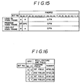
- the second frame address code FADR2 is a code mainly intended to show information concerning the video frames.
- the contents of the second frame address code FADR2 are shown in FIG. 15.
- the name and meaning of each code related to the second frame address code FADR2 will now be described.
- the total chapter number code TCN in the side is written into the chapter address code CADR in the lead-in video frame (FIG. 12), and the universal frame number code LFN in the last video frame in the program is written into the second frame address code FADR2 in the lead-in video frame.
- the universal frame number code LFN of the program last video frame is written into the free line FL having line number 564 in the lead-in area, it is possible to detect the recording length of information recorded on the video disk 7A by simply reading the free line FL having line number 564 without reading the TOC data. Hence, it is possible to obtain the recording length of information recorded on the video disk 7A even if a video disk player is used which has a specification in which only the No. 564 free line FL in the lead-in area is read and the TOC data is not read. Hence, it is possible to easily predict a pickup movement distance during search operation and to improve controllability.
- the total chapter number code TCN is recorded, together with the above-mentioned number code LFN, in the No. 564 free line.
- the TOC data contains information concerning the configuration and length of information recorded on the video disk 7A.
- the TOC data is recorded in a block unit. That is, a TOC data block TBLK is a unit of one video frame, and has a data structure which is completed within one video frame.
- the reason why the TOC data is designed to have the above block structure is that the TOC data can be managed in the block unit and written into a RAM built in the microcomputer in the block unit.
- use of the TOC data having the block structure cooperates with a recording in which identical TOC data blocks TBLK are multiplexed and repeatedly recorded (in 30 frames or more). Hence, if a dropout takes place during the reproducing operation and some information is lost, it is possible to re-read information by a jump-back operation in which information is read in the frame unit.
- TOC data blocks TBLK (30 video frames) located backwardly from the last video frame in the lead-in area. This arrangement in which at least 30 TOC data blocks TBLK are recorded is intended to ensure a margin in a re-reading area which is read when a dropout occurs in the reproduced RF signal due to track jumping of the pickup during the reproducing operation.
- each TOC data block TBLK is located in a video signal transmission area of video signals (C and Y video signals) in the MUSE signal transmission signal format (see FIG. 3).
- the video signals are not arranged in the lead-in area since they are not necessary, and a Y video signal area which originally has a black level is utilized.
- a video signal area is defined in each video field.
- One video signal area consists of 516 lines from line No. 47 to line No. 558.
- Another video signal area consists of 516 lines from line No. 609 to line No. 1120.
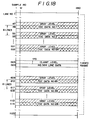
- C and Y video signal transmission areas are formed in each of the two 516 line areas. However, the C and Y video signal transmission areas are not needed, and hence an area between sample No. 13 and sample No. 480 is used as a TOC data area.
- the TOC data is arranged in an area starting from the No. 48 line and ending with the No. 552 line, and pieces of TOC data having TOC data No. 1 - TOC data No. 64 are arranged at equal intervals of eight lines. Further, the TOC data is arranged in an area starting from the No. 610 line and ending with the No. 1114, and pieces of TOC data having TOC data No. 65 - TOC data No. 128 are arranged at equal intervals of eight lines. Hence, 128 lines are provided in total for storing TOC data. In the above-mentioned manner, the TOC data is arranged in the No. 48 + 8n (n denotes the line number) lines and the No.
- the reason why the TOC data starts from the No. 48 line is, in addition to the above-mentioned aspect, that "gray level data" for settling of signal levels is arranged in a line located immediately before the TOC data. That is, the start line of the Y video signal area which is a usable area is the No. 47 line, and the gray level data is arranged in the No. 47 line. The TOC data is arranged in the No. 48 line immediately subsequent to the No. 47 line. The same thing can be said about the No.610 line. The gray level data will be described in detail later.
- the quantity of data which should be read within the above period is equal to 64 bits (8 bytes) other than the header SYNC in the 76-bit disk code DSCD. Hence, it is possible to read the above 64 bits within a period of 237.03 ⁇ s by means of general microcomputers.
- FIG. 19 shows the format of the TOC data.
- the TOC data has the same format as the disk code DSCD inserted into the No. 564 free line FL.
- the use of the common format makes it possible to commonly use the disk code reader 19 (FIG.2) in order to read the disk code DSCD and the TOC data, bringing an advantage of simple hardware structure.
- the TOC data includes, from sample No. 13 to sample No. 480, a header SYNC, an in-TOC information identification code TMODE, a chapter information code CIMFO, a frame information code FIMFO, an extended data code EDATA, and an error detection code CRCC.
- the header SYNC has the same format as the disk code DSCD (FIG. 10).
- the in-TOC information identification code TMOD is a code showing information concerning a TOC which is a table of contents of the TOC data.
- the name and meanings of each bit in the in-TOC information identification code TMODE will be described below.
- This code indicates additional information other than information concerning the structure of information on the video disk 7A, and an area for the users, and has the following contents.
- EDA Extended data area
- gray level data GLV is arranged in a line immediately prior to each TOC data. That is to say, one gray level data GLV is paired with one TOC data located in the same line as the above gray level data GLV.
- the gray level has the same definition as a clamp level, and its signal level is an 8-bit quantized level and has a value of "128/256".
- the quantized level is a level obtained by quantizing the range, which has a minimum value of "0" and a maximum value of "255", with equal 256 quantization levels as in the case of the disk code DSCD.
- the gray level is equal to "128/256".
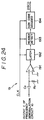
- FIG. 24 is a circuit diagram of the disk code reader 19 (see FIG. 2).
- the output c of the frequency demodulation circuit 10 is applied to a positive input terminal of a comparator 191 via a coupling capacitor Co.
- the positive input terminal of the comparator 191 is grounded via a bias resistor Ro.
- a negative input terminal of the comparator 191 is grounded.
- An output signal of the comparator 191 is applied to a latch circuit 192, which comprises a D-type flip-flop.
- a reference clock CLK is supplied to an clock input terminal of the latch circuit 192.
- the latch circuit 192 stores the output signal of the comparator 191 until the next reference clock CLK is generated.
- An output signal of the latch circuit 192 is supplied to a header detection circuit 193.
- the header detection circuit 193 comprises a digital comparator, which compares the pattern of the input code with the header SYNC of the disk code DSCD or TOC data, that is, a reference code including the same pattern as an 8-bit synchronizing pattern code. The result of this comparison is outputted, as a detection signal, by the header detection circuit 193.
- the detection signal outputted by the header detection circuit 193 is supplied to a disk code decoder 194.
- the output signal of the latch circuit 192 is sequentially written into the disk code decoder 194 in response to the header detection signal.
- the disk code decoder 194 determines whether or not a predetermined number of bits of bi-phase-modulated data has been received. When the result of this determination is affirmative, the disk code decoder 194 outputs data DSCD indicating the contents of the disk code.
- the disk code signal DSCD or TOC code signal in the MUSE signal c inputted to the comparator 191 is bi-phase-modulated in order to avoid the influence of a DC component, and is therefore made free from the DC component.
- the above code signal from which the DC component has been eliminated by means of the coupling capacitor Co is an alternate signal around zero level.
- the comparator 191 using a zero-cross comparator detects the rise edge and fall edge of the code signal with respect to the slice level corresponding to zero level.
- the gray level data GLV is a signal having an intermediate level equal to 128/256, and has a level approximately equal to the slice level of the comparator 191. Since the gray level data GLV is arranged immediately prior to the TOC data without exception, the gray level data GLV is inputted before the TOC data on the time base.
- the intermediate level of the MUSE signal C can be automatically settled at the slice level immediately before the TOC data is inputted irrespective of the state of a signal preceding the gray level data GLV as long as the values of the capacitor Co and the resistor Ro are suitably selected.
- the disk code reader 19 can correctly detect the edge of the TOC data from the leading bit thereof, and hence the TOC data can be correctly decoded.
- the disk code leader 19 can be connected to the output terminal of the frequency demodulation circuit 10 via a simple capacitance coupling using the capacitor Co, and can be configured by a simple structure.
- TOC information is recorded on the lead-in area on the video disks, it becomes possible to improve controllability.and operationability of the video disk players. Further, it is possible to improve management of TOC information and controllability of reproducing operation due to an arrangement in which the TOC information has a data structure completed in the frame unit and is repeatedly written into a plurality of frames.
Landscapes
- Engineering & Computer Science (AREA)
- Multimedia (AREA)
- Signal Processing (AREA)
- Television Signal Processing For Recording (AREA)
- Television Systems (AREA)
- Signal Processing For Digital Recording And Reproducing (AREA)
- Optical Recording Or Reproduction (AREA)
- Management Or Editing Of Information On Record Carriers (AREA)
Applications Claiming Priority (2)
| Application Number | Priority Date | Filing Date | Title |
|---|---|---|---|
| JP3257051A JPH0568226A (ja) | 1991-09-09 | 1991-09-09 | ビデオデイスクの信号記録方法 |
| JP257051/91 | 1991-09-09 |
Publications (2)
| Publication Number | Publication Date |
|---|---|
| EP0532278A2 true EP0532278A2 (de) | 1993-03-17 |
| EP0532278A3 EP0532278A3 (en) | 1994-06-08 |
Family
ID=17301059
Family Applications (1)
| Application Number | Title | Priority Date | Filing Date |
|---|---|---|---|
| EP19920308155 Withdrawn EP0532278A3 (en) | 1991-09-09 | 1992-09-09 | Method of recording information on video disk |
Country Status (3)
| Country | Link |
|---|---|
| US (1) | US5351132A (de) |
| EP (1) | EP0532278A3 (de) |
| JP (1) | JPH0568226A (de) |
Cited By (3)
| Publication number | Priority date | Publication date | Assignee | Title |
|---|---|---|---|---|
| EP0673034A3 (de) * | 1994-03-19 | 2000-09-06 | Sony Corporation | Optische Platte und Methode und Gerät zur Aufzeichnung auf und danach Wiedergabe von Informationen von dieser Platte |
| EP1139338A2 (de) * | 1994-03-19 | 2001-10-04 | Sony Corporation | Optische Platte und Verfahren und Gerät zur Aufzeichnung und Wiedergabe von dieser Platte |
| USRE38802E1 (en) | 1994-03-19 | 2005-09-27 | Sony Corporation | Method for reproducing compressed information data from a disk using a spatial frequency less than the track pitch |
Families Citing this family (15)
| Publication number | Priority date | Publication date | Assignee | Title |
|---|---|---|---|---|
| EP0686973B1 (de) | 1993-12-18 | 2002-10-16 | Sony Corporation | Datenwiedergabevorrichtung und datenaufzeichnungsmedium |
| JP3007523B2 (ja) * | 1994-01-26 | 2000-02-07 | ブラザー工業株式会社 | 映像再生装置 |
| JPH0845193A (ja) * | 1994-07-29 | 1996-02-16 | Pioneer Video Corp | 記録ディスク及び記録情報再生装置 |
| JP3614477B2 (ja) * | 1994-11-04 | 2005-01-26 | ティアック株式会社 | 光ディスク装置 |
| US5680159A (en) * | 1994-12-08 | 1997-10-21 | Interactive Sales Systems | Interactive display system using a laser disk player replaying video frames in response to touch force control monitor |
| KR0138459B1 (ko) * | 1994-12-30 | 1998-06-01 | 배순훈 | 비디오 컴팩트 디스크 플레이어에서의 선택화면 재생제어 방법 |
| US6002834A (en) * | 1995-02-24 | 1999-12-14 | Hitachi, Ltd. | Optical disk having table relating sector address and time and optical disk reproducing apparatus |
| US6009237A (en) * | 1995-02-24 | 1999-12-28 | Hitachi Ltd. | Optical disk and optical disk reproduction apparatus |
| KR0183160B1 (ko) * | 1995-09-30 | 1999-05-15 | 김광호 | 멀티 세션 디스크 및 고속 억세스 방법 |
| US5898462A (en) * | 1995-12-08 | 1999-04-27 | Coach Master International Corporation | Methods of producing data storage devices for appliances which can be used to coach users in the performance of user-selected tasks |
| JP3421897B2 (ja) * | 1996-03-29 | 2003-06-30 | ソニー株式会社 | データ記録及び/又は再生装置並びに方法 |
| US6895170B1 (en) * | 1998-10-09 | 2005-05-17 | Disney Enterprises, Inc. | Method and apparatus for storage and playback of programs recorded on random access storage media |
| JP3886800B2 (ja) * | 2001-12-19 | 2007-02-28 | 株式会社リコー | データ管理情報取得方法、情報再生装置、並びにデータ管理情報取得プログラム及び記録媒体 |
| IL162622A0 (en) * | 2001-12-21 | 2005-11-20 | Koninkl Philips Electronics Nv | Record carrier and scanning device |
| WO2004064045A2 (en) * | 2003-01-13 | 2004-07-29 | Disney Enterprises Inc. | Fast play dvd |
Family Cites Families (10)
| Publication number | Priority date | Publication date | Assignee | Title |
|---|---|---|---|---|
| US4321635A (en) * | 1979-04-20 | 1982-03-23 | Teac Corporation | Apparatus for selective retrieval of information streams or items |
| DE3011810A1 (de) * | 1980-03-27 | 1981-10-01 | Licentia Patent-Verwaltungs-Gmbh, 6000 Frankfurt | Verfahren und geraet zum auffinden eines speicherplatzes auf einem aufzeichnungstraeger |
| JPS59123381A (ja) * | 1982-12-29 | 1984-07-17 | Pioneer Electronic Corp | ビデオデイスクシステム |
| US4885644A (en) * | 1987-01-28 | 1989-12-05 | Pioneer Electronic Corporation | Spindle servo device for data recording disk reproducing apparatus |
| JPH01273268A (ja) * | 1988-04-25 | 1989-11-01 | Pioneer Electron Corp | 情報記録再生方法 |
| JPH0216879A (ja) * | 1988-07-05 | 1990-01-19 | Sanyo Electric Co Ltd | クランプ回路 |
| US5122886A (en) * | 1989-06-19 | 1992-06-16 | Pioneer Electronic Corporation | Selective information playback from recording medium based on user input content codes |
| US5148422A (en) * | 1989-08-25 | 1992-09-15 | Sony Corporation | Optical recording medium having a data recording track with offset data storing regions |
| JP2805095B2 (ja) * | 1989-10-31 | 1998-09-30 | ソニー株式会社 | 映像信号記録装置 |
| JPH03290863A (ja) * | 1990-04-06 | 1991-12-20 | Sony Corp | 両面連続再生型ビデオディスク装置 |
-
1991
- 1991-09-09 JP JP3257051A patent/JPH0568226A/ja active Pending
-
1992
- 1992-09-09 US US07/942,745 patent/US5351132A/en not_active Expired - Fee Related
- 1992-09-09 EP EP19920308155 patent/EP0532278A3/en not_active Withdrawn
Cited By (6)
| Publication number | Priority date | Publication date | Assignee | Title |
|---|---|---|---|---|
| EP0673034A3 (de) * | 1994-03-19 | 2000-09-06 | Sony Corporation | Optische Platte und Methode und Gerät zur Aufzeichnung auf und danach Wiedergabe von Informationen von dieser Platte |
| USRE37327E1 (en) | 1994-03-19 | 2001-08-14 | Sony Corporation | Method for reproducing compressed information data from a disk using a spatial frequency less than the track pitch |
| EP1139338A2 (de) * | 1994-03-19 | 2001-10-04 | Sony Corporation | Optische Platte und Verfahren und Gerät zur Aufzeichnung und Wiedergabe von dieser Platte |
| USRE38481E1 (en) | 1994-03-19 | 2004-03-30 | Sony Corporation | Method and apparatus for recording MPEG-compressed video data and compressed audio data on a disk |
| USRE38638E1 (en) | 1994-03-19 | 2004-10-26 | Sony Corporation | Optical disk having a particular format to store user-selected data, such as video data or computer files, including a dedicated TOC region |
| USRE38802E1 (en) | 1994-03-19 | 2005-09-27 | Sony Corporation | Method for reproducing compressed information data from a disk using a spatial frequency less than the track pitch |
Also Published As
| Publication number | Publication date |
|---|---|
| JPH0568226A (ja) | 1993-03-19 |
| EP0532278A3 (en) | 1994-06-08 |
| US5351132A (en) | 1994-09-27 |
Similar Documents
| Publication | Publication Date | Title |
|---|---|---|
| US5351132A (en) | Method of recording and reproducing information on a video disk utilizing table of contents data | |
| EP1163802B1 (de) | Verfahren zum einrichten einer systemszeituhr am anfang einer mpeg sequenz | |
| US8594491B2 (en) | Transport stream processing device, and associated methodology of generating and aligning source data packets in a physical data structure | |
| US7023486B2 (en) | Video signal processing device and method | |
| EP0268481B1 (de) | Verfahren zum Aufzeichnen von synchronisierter Audio- und Videoinformation | |
| US4772959A (en) | Digital signal recording and reproducing apparatus | |
| US4423440A (en) | Code signal reading apparatus | |
| US5940352A (en) | Record medium device for recording and reproducing time codes synchronized with input/reproduction signals into and from record medium having UTOC area, and record medium having UTOC area | |
| JP3154967B2 (ja) | ディジタルビデオディスク再生装置においてデスクランブリング信頼度を向上させる方法及び装置 | |
| US5162922A (en) | Apparatus for multi-channel dividing, recording and reproducing a video signal | |
| GB2240896A (en) | Coding audio signal for common image format video signal | |
| US5036404A (en) | Video disc player comprising clamping circuit for muse signal | |
| US4903148A (en) | Digital signal editing apparatus | |
| EP0532279A2 (de) | Verfahren zum Aufzeichnen von Informationen auf einer Videoplatte | |
| EP0532276A2 (de) | Verfahren zum Aufzeichnen von Informationen auf einer Videoplatte | |
| EP0532277A2 (de) | Verfahren zum Aufzeichnen von Informationen auf einer Videoplatte | |
| US7522223B2 (en) | Audio signal delay apparatus and method | |
| US6014492A (en) | Video signal recording and reproducing apparatus for digital video cassette tape recorder | |
| US5937135A (en) | Tape-independent video signal recording and reproducing apparatus | |
| JPS6052505B2 (ja) | Pcm信号復調装置 | |
| KR100255234B1 (ko) | 다치신호의 기록 및 재생방법과 다치신호기록용 동기신호발생회로 | |
| KR100257250B1 (ko) | 디지털 비디오 디스크의 위상동기루프 록킹상태 판별장치 | |
| US6154336A (en) | Frame synchronizing circuit in a magnetic recording and reproducing apparatus and a frame synchronizing method thereof | |
| JPS60231947A (ja) | コントロ−ルトラツクの記録方式 | |
| KR19980066957A (ko) | 씨디겸용 디지털비디오디스크 재생장치에서의 복조 및 동기검출,내삽,보호기능 장치 |
Legal Events
| Date | Code | Title | Description |
|---|---|---|---|
| PUAI | Public reference made under article 153(3) epc to a published international application that has entered the european phase |
Free format text: ORIGINAL CODE: 0009012 |
|
| AK | Designated contracting states |
Kind code of ref document: A2 Designated state(s): DE FR GB NL |
|
| PUAL | Search report despatched |
Free format text: ORIGINAL CODE: 0009013 |
|
| AK | Designated contracting states |
Kind code of ref document: A3 Designated state(s): DE FR GB NL |
|
| 17P | Request for examination filed |
Effective date: 19940929 |
|
| 17Q | First examination report despatched |
Effective date: 19950919 |
|
| 18D | Application deemed to be withdrawn |
Effective date: 19960330 |