EP0533120A2 - Optischer Sensor zur Leistungsüberwachung von Plotterschreibgeräte - Google Patents
Optischer Sensor zur Leistungsüberwachung von Plotterschreibgeräte Download PDFInfo
- Publication number
- EP0533120A2 EP0533120A2 EP92115795A EP92115795A EP0533120A2 EP 0533120 A2 EP0533120 A2 EP 0533120A2 EP 92115795 A EP92115795 A EP 92115795A EP 92115795 A EP92115795 A EP 92115795A EP 0533120 A2 EP0533120 A2 EP 0533120A2
- Authority
- EP
- European Patent Office
- Prior art keywords
- pen
- optical sensor
- carriage
- light source
- circuit
- Prior art date
- Legal status (The legal status is an assumption and is not a legal conclusion. Google has not performed a legal analysis and makes no representation as to the accuracy of the status listed.)
- Withdrawn
Links
Images


Classifications
-
- B—PERFORMING OPERATIONS; TRANSPORTING
- B43—WRITING OR DRAWING IMPLEMENTS; BUREAU ACCESSORIES
- B43L—ARTICLES FOR WRITING OR DRAWING UPON; WRITING OR DRAWING AIDS; ACCESSORIES FOR WRITING OR DRAWING
- B43L13/00—Drawing instruments, or writing or drawing appliances or accessories not otherwise provided for
- B43L13/02—Draughting machines or drawing devices for keeping parallelism
- B43L13/022—Draughting machines or drawing devices for keeping parallelism automatic
- B43L13/024—Drawing heads therefor
-
- G—PHYSICS
- G01—MEASURING; TESTING
- G01D—MEASURING NOT SPECIALLY ADAPTED FOR A SPECIFIC VARIABLE; ARRANGEMENTS FOR MEASURING TWO OR MORE VARIABLES NOT COVERED IN A SINGLE OTHER SUBCLASS; TARIFF METERING APPARATUS; MEASURING OR TESTING NOT OTHERWISE PROVIDED FOR
- G01D15/00—Component parts of recorders for measuring arrangements not specially adapted for a specific variable
- G01D15/16—Recording elements transferring recording material, e.g. ink, to the recording surface
-
- G—PHYSICS
- G06—COMPUTING OR CALCULATING; COUNTING
- G06K—GRAPHICAL DATA READING; PRESENTATION OF DATA; RECORD CARRIERS; HANDLING RECORD CARRIERS
- G06K15/00—Arrangements for producing a permanent visual presentation of the output data, e.g. computer output printers
- G06K15/22—Arrangements for producing a permanent visual presentation of the output data, e.g. computer output printers using plotters
-
- G—PHYSICS
- G06—COMPUTING OR CALCULATING; COUNTING
- G06K—GRAPHICAL DATA READING; PRESENTATION OF DATA; RECORD CARRIERS; HANDLING RECORD CARRIERS
- G06K5/00—Methods or arrangements for verifying the correctness of markings on a record carrier; Column detection devices
Definitions
- the invention relates to an optical sensor for monitoring plotter pen performance.
- Such a sensor is used in pen plotters to monitor and control the quality of pen markings on plotting media.
- a typical pen plotter comprises a pen for producing markings on a medium in response to instructions from, for example, a computer.
- the medium such as paper ia movable in a first direction along the x-axis and the pen on a main carriage is movable in a second direction along the y-axis which is perpendicular to the first direction.
- the writing system also typically comprises a rotatable pen carousel carrying a plurality of pens, for example pens of different colors.
- a pen handling mechanism is provided which permits a pen to move from the pen carousel into a position on the carriage for plotting on the medium and replaces that pen by another one from the carousel, for example when a different color is desired.
- a related object is to minimize the human supervision required of operating the plotter..
- Another object is to provide a pen verification system which takes into account the different drawing characteristics of all types of pens such as fiber-tip paper pens, fiber-tip transparency pens, rollerball pens, drafting pens for vellum and paper, and drafting pens for polyester film.
- a related object is to provide a pen verification system that provides predictable performance for different color pens, different line thicknesses, varied pen speeds and pen pressures, and all media types such as paper, vellum, polyester and translucent material.
- a further object is to provide adequate optical sensing of pen lines under varying ambient light conditions.
- an optical sensor for monitoring plotter pen performance by sensing the quality of lines drawn on a medium.
- An LED emitting a green light beam is angularly directed toward an underlying line so as to reflect into an optical sensor which measures the print contrast ratio of a point on the line.
- Circuit means amplifies and filters the signal generated by the optical sensor.
- the invention provides a method of monitoring and controlling the quality of pen markings on a plotting medium by qualifying each pen based on optically sensing across a sample line drawing on an actual medium. During each subsequent plotting task of a particular pen which has been qualified, an actual line plot is optically sensed across a selected point to make a comparison with the sample line. If the actual line plot is unsatisfactory, the deficient pen is replaced and the plot is restarted from the beginning, or retraced from the last good verification, or is stopped to allow the user to select an appropriate corrective procedure.
- a method for comparing a test line of a plotter pen with a subsequent plot line in order to compare selected points on the plot line with a benchmark for that particular pen.
- Each pen in a plotter carousel is qualified by monitoring the print contrast ratio of multiple points taken from vertical and horizontal portions of a sample line drawn by the pen.
- a record is maintained to indicate the good or bad qualification status of each pen in the carousel, and the appropriate benchmark for each pen is stored for future reference.
- the invention is incorporated in a pen plotter comprising a pen for producing markings such as graphical representations on a medium, for example on a sheet of paper.
- the pen is held on a main carriage by a z-axis carriage which can be lowered such that the tip of the pen contacts the medium in order to produce markings thereon.
- the pen comprises an ink reservoir containing ink of a certain color.
- the pen is held on the z-axis carriage in a way so that it can easily be replaced by another pen, for example if a different color for the graphical representation is desired or if the ink reservoir in the pen is empty.
- the replacement of the pen can be done manually by a user, but it is preferred to perform the replacement automatically under computer control.
- a pen carousel (not shown) from which they can be transported to the z-axis carriage and inserted there.
- the paper is moved in a first direction (X-direction) and the main carriage is moved in a second direction (Y-direction) orthogonal thereto.
- the driving of the paper can be accomplished by means of a grit wheel and pinch wheel assembly between which the paper is moved.
- the invention is not limited to any particular type of plotter, but can be utilized in any plotter configuration where line vectors are drawn on media by pens.
- another type of plotter which may utilized the invention holds the paper stationary while the main carriage is movable in the X- and Y-directions so that the pen can be placed on any desired point of a media sheet.
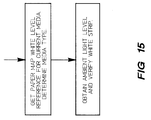
- a sensing system intermittently monitors the quality of the pen on the media by scanning across a point on a line, with the point overlying a white reference strip in the platen and illuminated by light emitted from a light source such as an LED emitting a beam of green light.
- the output signals of the sensing system are amplified, filtered and converted into digital data.
- This digital data is then supplied to a microprocessor for comparison with the benchmark data stored for that particular pen (or type of pen). In response to such comparison, the microprocessor provides output signals indicating a good pen or a bad pen.
- Various corrective actions can be taken when a bad pen is detected by the sensing system, or that a good pen is malfunctioning.
- the plotter can be pre-programmed so that the bad/malfunctioning pen is automatically replaced by another pen, or that user can be warned that a writing error has occurred so that he can decide on appropriate action, or those markings which do not meet the desired quality can be replotted.
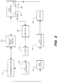
- Fig. 1 is a block diagram showing the circuit interconnections between a microprocessor (not shown) and the various functional components of the plotter.
- the mechanical components include a pen carriage 20, front panel 22, turret drive 26 for a pen storage carousel (not shown), and ID indicia 30 on the pen storage carousel to indicate the type of pens available therein for plotting.
- a keyboard driver 34 connects through a VFD/keyboard latch 36 to receive inputs from the microprocessor and to provide inputs to a vacuum fluorescent display on the front panel 22.
- the display also receives inputs from the microprocessor.
- the turret drive 26 receives inputs from the microprocessor through a carousel driver 42 to rotate the carousel to a proper position for transferring pens back and forth between the carousel and the pen carriage.
- a carousel sensor 44 interacts with the ID indicia 30 to identify which carousel slots are empty and which type of pens are in each of the other carousel slots.
- a servo integrated circuit 50 receives inputs from the microprocessor and also interconnects an X-encoder 52 through an X-drive 54 to an X-motor 56 in order to monitor the position of the medium in the X-direction and then cause the X-motor to move the medium to a new position.
- interconnections are made from a Y-encoder 58 through a Y-drive 60 to a Y-motor 62 in order to monitor the position of the pen carriage in the Y-direction and then cause the Y-motor to move the pen carriage to a new position.
- a fan/roll latch 64 receives inputs from the microprocessor to a fan drive 66 to operate a fan 68 which provides a vacuum through holes in the platen to help hold the media securely at the point where a pen is drawing vectors on the media.
- the latch 64 also provides inputs through a rollfeed drive 70 to a media roll 72 for bringing media into position under the pen carriage 20 in order to commence a new plot.
- a pen lift 74 is included with the other drives on an analog printed circuit assembly 76 and receives inputs from the microprocessor through the servo IC 50 and then sends output signals to the pen carriage 20 in order to move the pen from a normally raised position to a lowered position into contact with the media at the point where it overlies the platen.
- Optical sensor circuits 78 provide input signals to a light source on the pen carriage 20 and then process output signals from the optical sensor on the pen carriage 20 back to the microprocessor.
- a light source in the form of an LED 80 and a optical sensor 82 are directly mounted on the pen carriage 20, a pen-lift drive circuit 83 is interconnected between the microprocessor 79 and the pen carriage 20 to move the carriage into the optimum focal distance above the media.
- Signals from the microprocessor 79 are passed through latch 84 to a digital/analog converter 86 which produces an output signal which passes through driver 88 to the LED 80.
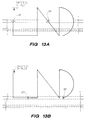
- the LED transmits a wide beam of light (see outwardly flared arrows schematically extending below LED 80 in Fig.
- a customized platen 102 is provided.
- the invention provides a white reference strip 108 (see Fig. 3) which extends parallel to the drawing notch 104 in the Y-direction, with the strip and notch having the same predetermined offset 110 along their full length.
- the white reference strip in the presently preferred embodiment is formed by a white tape which is recessed below the surface of the platen 102 in a groove 112 as to be positioned along the bottom surface of the groove without the tape visibly extending up either side 113 of the groove.
- a main carriage 120 carries variously positioned Y-direction tires 122 mounted on bearings 124, and a bumper 123, to facilitate the movement along the Y-axis.
- the main carriage In order to provide movement of the z-carriage and the pen between a raised position to a lowered position (see the double pointed arrows in Fig. 8), the main carriage also carries a magnetic cup 126 and a Z-direction tire 130 for engagement with a Z-axis carriage 128.
- An energized coil 132 mounted on an insert 133 in the Z-axis carriage is magnetically pushed away from its matching magnetic cup 126 to move the pen into the down position.
- a carriage PCB 138 carries the encoder 136 and also provides the circuit interconnections through wires 140 to the coil as well as the circuit interconnections to the LED 80 and the sensor 82.
- a stationary inner linear bearing 142 engages a matching moving outer bearing sleeve 143, and an expansion spring 144 holds the z-carriage in a normally raised position.
- a compression spring 146 forces a pawl 148 into locking engagement against the outer pen casing 150 (see Fig. 7).
- each plotter it is preferable to calibrate each plotter before it is used in order to optimize the ability of the sensor to measure the light intensity of a plotted line. Accordingly, as best shown in Fig. 8, the pen is removed and a paper feeler 152 can then be used to determine the actual distance to a sheet of underlying media for this particular plotter. In addition, the paper feeler can scan the platen along the entire length of the Y-axis to determine variations in this actual distance measurement. Such actual distances measured during calibration are recorded in memory so that during normal operation the Z-axis carriage can be moved to achieve the optimum focal distances as shown in mm in the drawing of Fig. 8.
- the sensor 82 is shown in detail in Figs. 9-10 and includes a casing 160, a chip assembly 162, a cap 164, and a sleeve 166 having a bracket 168 for holding the LED 80.
- the sleeve snaps into position at the bottom of the casing 169 and holds the lens in fixed position inside the sleeve at the lower end of the casing.
- the chip assembly includes a photodiode as well as a two-stage amplifier, and the lower portion 179 of the chip assembly is transparent (such as clear plastic) to allow reflected light to pass unimpeded to the photodiode.
- the cap 164 must fit snugly over the top end of the chip assembly to nest into a casing receptacle to prevent any extraneous light from passing through to the photodiode.
- both the sensor and the LED are shown at an angle with respect to the Z-direction, it is possible to have other angular positioning of the sensor, so long as the LED preferably emits light at an angle to avoid undue specular glare from the media.
- the invention provides a method and apparatus for using a uniquely designed optical sensor that periodically senses the quality of plotted lines by scanning across selected points on the lines, and measuring the difference in contrast between the actual plotted line and a benchmark such as a default value or an actual value obtained when that particular pen was qualified.
- a benchmark such as a default value or an actual value obtained when that particular pen was qualified.
- Fig. 12 shows in more detail the processing of the output signal from the sensor through op-amp 180, resistors 182, 183 filter circuits 184, 185 and A/D converter 186.
- Fig. 11 shows the interconnections between PCB 1 (processor), PCB 2 (carriage) and PCB 3 (sensor) including the LED input 188, the sensor output 190, the encoder circuits 192 and the coil circuits 194.
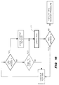
- the first percentage measurement at 200 is based on the percentage drop in reflected signal intensity from total white to absolute dark (total light absorbance). Thus, if five of the proposed six points each show a print contrast ratio of less than 8 %, then it is ok to proceed to the next stage of actually drawing the sample plot as shown at 202.
- the average intensity of the PCRs for five points is computed, and then so long as the pen plots checked during the pen verification procedure have PCRs of not less than 40 % of such average, then the plots actually tested are deemed satisfactory. If a user is using only black pens and does not need high quality plotting, it is possible to forego the actual pen qualification procedure and just accept that any pen having a print contrast ratio of more than the default of 8 % on the scale of percentage signal drop from all white to total darkness will be deemed a "good" pen.
Landscapes
- Engineering & Computer Science (AREA)
- Physics & Mathematics (AREA)
- General Physics & Mathematics (AREA)
- Theoretical Computer Science (AREA)
- Automation & Control Theory (AREA)
- General Engineering & Computer Science (AREA)
- Position Input By Displaying (AREA)
- Recording Measured Values (AREA)
Applications Claiming Priority (2)
| Application Number | Priority Date | Filing Date | Title |
|---|---|---|---|
| US763098 | 1991-09-20 | ||
| US07/763,098 US5170047A (en) | 1991-09-20 | 1991-09-20 | Optical sensor for plotter pen verification |
Publications (2)
| Publication Number | Publication Date |
|---|---|
| EP0533120A2 true EP0533120A2 (de) | 1993-03-24 |
| EP0533120A3 EP0533120A3 (de) | 1993-05-12 |
Family
ID=25066876
Family Applications (1)
| Application Number | Title | Priority Date | Filing Date |
|---|---|---|---|
| EP19920115795 Withdrawn EP0533120A3 (de) | 1991-09-20 | 1992-09-16 | Optischer Sensor zur Leistungsüberwachung von Plotterschreibgeräte |
Country Status (3)
| Country | Link |
|---|---|
| US (1) | US5170047A (de) |
| EP (1) | EP0533120A3 (de) |
| JP (1) | JPH05208586A (de) |
Families Citing this family (31)
| Publication number | Priority date | Publication date | Assignee | Title |
|---|---|---|---|---|
| US5905512A (en) * | 1991-09-20 | 1999-05-18 | Hewlett-Packard Company | Unitary light tube for mounting optical sensor components on an inkjet printer carriage |
| US5404425A (en) * | 1992-05-05 | 1995-04-04 | Calcomp Inc. | Pen operability checking system for vector plotters |
| US5448269A (en) * | 1993-04-30 | 1995-09-05 | Hewlett-Packard Company | Multiple inkjet cartridge alignment for bidirectional printing by scanning a reference pattern |
| US5883646A (en) * | 1993-04-30 | 1999-03-16 | Hewlett-Packard Company | Compact flex-circuit for modular assembly of optical sensor components in an inkjet printer |
| US5341689A (en) * | 1993-04-30 | 1994-08-30 | Calcomp Inc. | Pen force gage for a pen plotter |
| US5397192A (en) * | 1993-11-01 | 1995-03-14 | Hewlett-Packard Company | Shuttle-type printers and methods for operating same |
| JPH082181A (ja) * | 1994-06-24 | 1996-01-09 | Kenji Okayasu | 図形描画装置の制御方法及び図形描画装置及び波形記録装置 |
| US6325505B1 (en) | 1997-06-30 | 2001-12-04 | Hewlett-Packard Company | Media type detection system for inkjet printing |
| US6425650B1 (en) | 1997-06-30 | 2002-07-30 | Hewlett-Packard Company | Educatable media determination system for inkjet printing |
| US6386669B1 (en) | 1997-06-30 | 2002-05-14 | Hewlett-Packard Company | Two-stage media determination system for inkjet printing |
| US6585341B1 (en) | 1997-06-30 | 2003-07-01 | Hewlett-Packard Company | Back-branding media determination system for inkjet printing |
| US6561643B1 (en) | 1997-06-30 | 2003-05-13 | Hewlett-Packard Co. | Advanced media determination system for inkjet printing |
| US6036298A (en) * | 1997-06-30 | 2000-03-14 | Hewlett-Packard Company | Monochromatic optical sensing system for inkjet printing |
| US6494563B2 (en) | 1997-12-25 | 2002-12-17 | Canon Kabushiki Kaisha | Ink jet element substrate and ink jet head that employs the substrate, and ink jet apparatus on which the head is mounted |
| US6286927B1 (en) * | 1997-12-25 | 2001-09-11 | Canon Kabushiki Kaisha | Ink jet element substrate and ink jet head that employs the substrate, and ink jet apparatus on which the head is mounted |
| US6361137B1 (en) * | 1998-09-28 | 2002-03-26 | Hewlett-Packard Company | Method and apparatus for compensating for variations in printhead-to-media spacing and printhead scanning velocity in an ink-jet hard copy apparatus |
| US6352332B1 (en) | 1999-07-08 | 2002-03-05 | Hewlett-Packard Company | Method and apparatus for printing zone print media edge detection |
| US6361139B1 (en) * | 2000-01-31 | 2002-03-26 | Hewlett-Packard Company | Self-calibrated sensor module for inkjet printing devices |
| EP1321310A1 (de) * | 2001-12-21 | 2003-06-25 | Schächter, Friedrich | Prüfverfahren für Schreibgeräte |
| US6612680B1 (en) | 2002-06-28 | 2003-09-02 | Lexmark International, Inc. | Method of imaging substance depletion detection for an imaging device |
| US7285771B2 (en) * | 2004-01-20 | 2007-10-23 | Hewlett-Packard Development Company, L.P. | Optical sensor |
| TWI244320B (en) * | 2004-10-20 | 2005-11-21 | Asia Optical Co Inc | Scanning unit having anti-reflective layers with high reflectivity |
| JP4670361B2 (ja) * | 2005-01-20 | 2011-04-13 | 船井電機株式会社 | プリンタ |
| US8291001B2 (en) * | 2008-02-27 | 2012-10-16 | Eastman Kodak Company | Signal processing for media type identification |
| US8251478B2 (en) | 2008-02-27 | 2012-08-28 | Eastman Kodak Company | Signal processing of recording medium indicia |
| US7800089B2 (en) * | 2008-02-27 | 2010-09-21 | Eastman Kodak Company | Optical sensor for a printer |
| US8739407B2 (en) | 2011-12-09 | 2014-06-03 | Eastman Kodak Company | Method of assembling an optical sensor assembly for a carriage printer |
| US20130147877A1 (en) | 2011-12-09 | 2013-06-13 | Juan Manuel Jimenez | Carriage printer with optical sensor assembly |
| DE102016103113A1 (de) * | 2016-02-23 | 2017-08-24 | Vishay Semiconductor Gmbh | Optoelektronische Vorrichtung |
| DE102016103123A1 (de) * | 2016-02-23 | 2017-08-24 | Vishay Semiconductor Gmbh | Optoelektronische Vorrichtung |
| US10564734B1 (en) * | 2018-08-23 | 2020-02-18 | Pixart Imaging Inc. | Pen mouse with a tracing compensation function |
Family Cites Families (10)
| Publication number | Priority date | Publication date | Assignee | Title |
|---|---|---|---|---|
| US3609237A (en) * | 1969-01-27 | 1971-09-28 | Gerber Scientific Instr Co | Line or edge digitizing system with means for automatically outputting only data truly representative of the line or edge being digitized |
| US3711717A (en) * | 1970-09-16 | 1973-01-16 | Gerber Scientific Instr Co | Optical line follower |
| US3845319A (en) * | 1971-10-22 | 1974-10-29 | Sick Erwin | Method and apparatus for the accurate detection of the passage of the edge of a straight contrast jump |
| JPS5136416B2 (de) * | 1972-03-27 | 1976-10-08 | ||
| JPS5263755A (en) * | 1975-11-22 | 1977-05-26 | Nippon Chemical Ind | Pattern line width measuring device |
| US4435674A (en) * | 1981-10-05 | 1984-03-06 | The Gerber Scientific Instrument Company | Method and apparatus for generating a verified plot |
| JPH0617777B2 (ja) * | 1984-06-02 | 1994-03-09 | 大日本スクリーン製造株式会社 | プリント配線板の撮像方法 |
| DE3505525C1 (de) * | 1985-02-18 | 1986-04-10 | ESAB-HANCOCK GmbH, 6367 Karben | Fotoelektrische Einrichtung zum Nachfuehren eines Abtastkopfes laengs einer Vorlagenbahn |
| EP0393291B1 (de) * | 1989-04-20 | 1995-08-23 | Hewlett-Packard Company | Drucksystem und -verfahren zum Erzeugen sichtbarer Markierungen auf einem Träger |
| US4920357A (en) * | 1989-06-29 | 1990-04-24 | Hewlett-Packard Company | Unattended replacement of plotter pens |
-
1991
- 1991-09-20 US US07/763,098 patent/US5170047A/en not_active Expired - Lifetime
-
1992
- 1992-09-16 EP EP19920115795 patent/EP0533120A3/de not_active Withdrawn
- 1992-09-18 JP JP4274989A patent/JPH05208586A/ja active Pending
Also Published As
| Publication number | Publication date |
|---|---|
| JPH05208586A (ja) | 1993-08-20 |
| EP0533120A3 (de) | 1993-05-12 |
| US5170047A (en) | 1992-12-08 |
Similar Documents
| Publication | Publication Date | Title |
|---|---|---|
| US5170047A (en) | Optical sensor for plotter pen verification | |
| US5262797A (en) | Monitoring and controlling quality of pen markings on plotting media | |
| US5261038A (en) | Pen qualification and verification in a graphics plotter | |
| US6290320B1 (en) | Calibration technique for test patterns from multiple color inkjet printheads | |
| US7458147B2 (en) | Method for determining whether a component holder is defective | |
| US20010000055A1 (en) | Replaceable donor sheet assembly with memory for use with a thermal printer | |
| US20080174763A1 (en) | Color Measuring head and Scanner Device Equipped Therewith | |
| JP2000504501A (ja) | 担体上に構成要素を配置する方法及び機械、並びにこの方法及び機械に使用する較正担体検出装置 | |
| JPS6244289B2 (de) | ||
| US6386676B1 (en) | Reflective type media sensing methodology | |
| US6295129B1 (en) | Arrangement and method for marking defects | |
| US20100255600A1 (en) | Liquid handling device | |
| EP0393291A1 (de) | Drucksystem und -verfahren zum Erzeugen sichtbarer Markierungen auf einem Träger | |
| EP0631258A1 (de) | Verfahren und Vorrichtung zur automatischen Änderung der Betriebsbedingungen von Machinen oder Apparaten | |
| JPH06244598A (ja) | 電子部品実装装置及び部品実装方法 | |
| JP2006210705A (ja) | 電子部品実装装置 | |
| JP3521625B2 (ja) | インク残量検知装置 | |
| US6907356B2 (en) | Encoder strip damage detector | |
| CN217981272U (zh) | 检测设备 | |
| KR200375174Y1 (ko) | 토너카트리지 검사장치 | |
| US20060169763A1 (en) | Automatically labeling and inspecting apparatus and method of use | |
| JPS61195845A (ja) | 印刷状態検査装置 | |
| JPH0599634A (ja) | 外観検査装置 | |
| JP3693279B2 (ja) | 物品の形状測定装置 | |
| JPH09136498A (ja) | プロッタの用紙検出方法 |
Legal Events
| Date | Code | Title | Description |
|---|---|---|---|
| PUAI | Public reference made under article 153(3) epc to a published international application that has entered the european phase |
Free format text: ORIGINAL CODE: 0009012 |
|
| AK | Designated contracting states |
Kind code of ref document: A2 Designated state(s): DE ES FR GB IT |
|
| PUAL | Search report despatched |
Free format text: ORIGINAL CODE: 0009013 |
|
| AK | Designated contracting states |
Kind code of ref document: A3 Designated state(s): DE ES FR GB IT |
|
| 17P | Request for examination filed |
Effective date: 19930830 |
|
| 17Q | First examination report despatched |
Effective date: 19960624 |
|
| 18D | Application deemed to be withdrawn |
Effective date: 19970108 |