EP0533729B1 - Dispositif de decharge de traction de cable - Google Patents
Dispositif de decharge de traction de cable Download PDFInfo
- Publication number
- EP0533729B1 EP0533729B1 EP91910617A EP91910617A EP0533729B1 EP 0533729 B1 EP0533729 B1 EP 0533729B1 EP 91910617 A EP91910617 A EP 91910617A EP 91910617 A EP91910617 A EP 91910617A EP 0533729 B1 EP0533729 B1 EP 0533729B1
- Authority
- EP
- European Patent Office
- Prior art keywords
- cable
- strain relief
- arrangement
- cable strain
- housing
- Prior art date
- Legal status (The legal status is an assumption and is not a legal conclusion. Google has not performed a legal analysis and makes no representation as to the accuracy of the status listed.)
- Expired - Lifetime
Links
Images


Classifications
-
- H—ELECTRICITY
- H01—ELECTRIC ELEMENTS
- H01R—ELECTRICALLY-CONDUCTIVE CONNECTIONS; STRUCTURAL ASSOCIATIONS OF A PLURALITY OF MUTUALLY-INSULATED ELECTRICAL CONNECTING ELEMENTS; COUPLING DEVICES; CURRENT COLLECTORS
- H01R13/00—Details of coupling devices of the kinds covered by groups H01R12/70 or H01R24/00 - H01R33/00
- H01R13/58—Means for relieving strain on wire connection, e.g. cord grip, for avoiding loosening of connections between wires and terminals within a coupling device terminating a cable
- H01R13/5804—Means for relieving strain on wire connection, e.g. cord grip, for avoiding loosening of connections between wires and terminals within a coupling device terminating a cable comprising a separate cable clamping part
- H01R13/5816—Means for relieving strain on wire connection, e.g. cord grip, for avoiding loosening of connections between wires and terminals within a coupling device terminating a cable comprising a separate cable clamping part for cables passing through an aperture in a housing wall, the separate part being captured between cable and contour of aperture
Definitions
- the invention relates to an arrangement for cable strain relief, with a cable, a sheathing of the cable, with means for fastening it to a body which absorbs the tensile load and with a clamping part with which the cable is pressed together and fixed relative to the sheathing.
- DE-OS 23 40 314 describes a strain-relieved cable bushing in which a holding element, for example made of an elastic plastic, is seated in an opening in a housing wall and is molded onto the cable.
- a holding element for example made of an elastic plastic
- the outer cable jacket in the area of the extrusion coating is removed and the jackets of the individual wires are roughened, so that sufficient strain relief for the individual wires is ensured.
- DE-OS 27 48 419 describes a seal for a submersible motor or the like.
- the seal closes an opening in the housing for the motor through which a covered electrical strand is passed.
- the seal includes a pipe socket attached to the inside of the housing and coaxially surrounding the opening, and a cylindrical sealing element made of an elastomeric material with an axial passage for the encased strand.
- the outer diameter of the sealing element is larger than the inner diameter of the pipe socket, and the diameter of the axial passage is larger than the outer diameter of the casing. If the sealing element is pressed into the pipe socket, the diameter of the passage is reduced and the sealing element presses against the casing.
- a clamping ring is attached to the inside of the casing on the covered strand so that it comes into contact with the sealing element when the strand is pulled outward with respect to the housing.
- DE-OS 34 09 906 describes a cable grommet for fixing and stiffening a cable passed through an opening in a device.
- the cable grommet consists of an elongated hollow body made of a resilient material and has a thickening in the region of the opening with a groove arranged therein.
- the inner diameter of the hollow body is at least at one clamping point smaller than the outer diameter of the cable.
- the opening has a funnel-shaped extension inside the device. The thickening of the hollow body lies against the extension within the groove.
- the thickening becomes against the funnel-shaped extension pressed and thus the diameter of the hollow body in the region of the extension is reduced, with the result that the more that is pulled, the more the hollow body is pressed against the cable.
- This object is achieved according to the invention in an arrangement for cable strain relief of the type mentioned at the outset in that the separate clamping part rests on the cable and in that the sheathing surrounds the clamping part and a cable piece enclosing the compressed area.
- the individual cores of a multi-core cable are also reliably strain relieved.
- the cable is clamped by the clamping part anchored in the sheathing in such a way that the individual wires to the sheath are relieved of strain.
- the sheathing is advantageously molded onto the clamping part and the cable piece by means of extrusion coating.
- the production of the cable strain relief according to the invention is particularly simple, because there is no need for reworking after the encapsulation. Since the sprayed-on material lies seamlessly on the surfaces of the clamping part and the cable piece, the anchoring of the clamping part and cable piece in the sheathing is further improved by the extrusion coating.
- the clamping part has a U-profile, the distance between the legs being smaller than the diameter of the cable in the non-compressed state, and if the cable is held between the two legs.
- the clamping part shaped in this way can be easily attached and can be designed so massively that it is considerable Can exert pressure on the cable. Due to its shape, it is strongly anchored in the sheath - and with it the pinched cable.
- the clamping part is designed as a sleeve which is pressed together at least at one point to such an extent that the smallest distance between opposing regions of the sleeve inner wall is smaller than the diameter of the cable in the uncompressed state.
- the cable is passed through the sleeve.
- the anchoring of the clamping part designed in this way in the casing can be further improved if the sleeve has at least one end-like flange-like widening.
- the covering advantageously consists of an elastic plastic or a rubber-like material. These materials can be easily sprayed on in the uncured state and then polymerized or vulcanized.
- plastics from the group of polyvinyl chloride, polyurethane and a mixture of the two materials are particularly favorable.
- the clamping part can consist both of a material that permanently deforms during bending and of an elastic material.
- This option also opens up many possible variations in the manufacture of the cable strain relief, in particular if the sheathing is produced by means of extrusion coating.
- the clamping part consists of a permanently bending material the cable is pressed together with the clamping part and then the cable with the attached clamping part is placed in the injection mold. If the clamping part consists of an elastic material, then it is necessary that a device which compresses the clamping part and the cable is present in the injection mold, the shape of the clamping part and the cable produced thereby being "frozen" during the encapsulation.
- the clamping part advantageously consists of a metal or a plastic with a higher melting point than the enveloping material.
- the means for fastening the arrangement for cable strain relief to the sheath are directly molded and / or fixed.
- Further advantageous configurations of the means are present if the means form extensions projecting from the sheathing, if the means have at least two mutually facing boundaries and are adapted to the body in such a way that when the cable strain relief is attached to the body, the two boundaries on at least one wall of the body, and if each of the two limits mentioned and an adjoining non-widening area of the wrapping encompass an edge of the wall. All structural elements required in these configurations, which have to be produced on or in the casing, can be molded directly when the clamping part and the cable piece are encapsulated. Special precautions on the body that is to accommodate the strain relief are to accommodate the cable strain relief according to the invention not mandatory. Cable strain reliefs designed in this way can be very easily attached to the body.
- the arrangement according to the invention for cable strain relief can advantageously be used if the body is designed as a housing with a feedthrough for the cable, if the covering fits into the feedthrough in some areas, if the means are designed such that they are connected to the cable strain relief when inserted into the feedthrough mentioned limits on the wall of the housing limiting the implementation. If the cable strain relief is inserted into the bushing, which is required in any case for the insertion of the cable into the housing, then a particularly stable fastening of the cable strain relief on the housing can be achieved in a simple manner.
- the cable strain relief according to the invention is advantageously equipped in such a way that the mutually facing limits of the means form the walls of at least one annular groove so that the annular groove has a width , which is adapted to the thickness of the wall (walls) of the housing cover or the lower housing part, that the outer and the inner contour of the annular groove is geometrically approximately similar to the opening formed by the one pair of recesses and that the inner diameter of the annular groove is the same as or smaller and its outer diameter is larger than the diameter of the bushing.
- the ring groove is at Overmoulding of the cable and the clamping part and the housing require no additional changes beyond the recesses which are required anyway.
- this embodiment of the arrangement for cable strain relief according to the invention there is another advantage that it closes the implementation moisture-proof.
- the attachment of the cable strain relief to the housing - especially when the hood is removed - can be improved even more if the housing is double-walled and the bushing is formed from two pairs of abutting recesses in the housing and inner walls of the housing hood or the lower housing part, if for each pair of Recesses an annular groove is provided and when the position of the two annular grooves is adapted to each other to the position of the two pairs of recesses.
- the clamping part is arranged in the region of the sheathing framed by the ring grooves.
- an advantageous embodiment of the cable strain relief according to the invention is equipped in such a way that the sheath as a means has a directly formed extension which projects from it and surrounds it in a ring shape, in that a limitation of the extension Adjacent area of the sheath fits through the opening, that the extension lies with the cable strain relief inserted in the opening on the housing wall and protrudes all around the edge of the opening, and that the other means is attached to said area adjacent to the extension.
- a mechanically particularly stable anchoring of the cable strain relief in the opening is given if at least one hole is formed in the area adjacent to the extension, which runs approximately parallel to the extension, which is approximately at a distance from the extension which is equal to or is greater than the thickness of the housing wall, and if there is a pin that fits into the hole as another means.
- the hole, as well as the extension can be directly molded when the clamping part and the cable piece are overmolded.
- the pin is only inserted into the hole after the casing has been pushed into the opening until the extension on the housing wall stops. The pin prevents the cable strain relief from being pulled out of the opening.
- the cable strain relief can no longer be moved relative to the housing and the opening is sealed moisture-proof.
- the anchoring of the cable strain relief can be improved even more if two holes - one on each side of the cable - are provided and the pin is designed as a U-shaped bracket, the distance between the legs of which is equal to the distance between the holes.
- a further very stable anchoring of the cable strain relief in the opening can be achieved if an annular groove is formed in the area adjacent to the extension, which lies in a plane that runs approximately parallel to the extension, which is approximately a distance from the extension has, which is equal to or greater than the thickness of the housing wall and if, as another means, a clip fitting into the annular groove is present.
- the annular groove can be formed directly when the clamping part and the cable piece are encapsulated.
- the clip is only pushed into the ring groove after the casing has been pushed into the opening until the extension on the housing wall stops.
- the clamp prevents the cable strain relief from being pulled out of the opening. If the distance between the extension (measured at the outer edge facing the ring groove) and the ring groove is equal to the thickness of the housing wall, the cable strain relief can no longer be moved relative to the housing and the opening is sealed moisture-proof.
- the feedthrough and the cut parallel to the feedthrough have approximately the same non-round shape through the wrapping area inserted in the feedthrough. This ensures that the cable strain relief is secured against rotation.
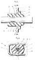
- a cable strain relief 1 shown in Figures 1 and 2 belongs to a housing which consists of a housing cover and a lower housing part and which is at least where the housing cover and the lower housing part abut, is double-walled, that is to say that the housing hood has a housing wall 12 and one Inner wall 13 and the lower housing part have a housing wall 14 and an inner wall 15.
- a recess is formed in the mutually facing edges of the housing and inner walls, the two recesses 8 and 9 in the housing walls 12 and 14 and the two recesses 10 and 11 in the inner walls 13 and 15 being opposite one another and complementing each other to form circular openings.
- the two openings form a feedthrough for the cable, into which the cable strain relief 1 is fitted in the arrangement shown in FIG.
- the cable strain relief 1 consists of a sheath 2 and a clamping part 6.
- the clamping part 6 has a U-profile and is plugged onto a cable 3. Since the leg distance of the clamping part 6 is smaller than the cable diameter, the cable 3 is compressed by the clamping part 6.
- the clamping part 6 and a cable area on both sides of the Clamping parts 6 are extrusion-coated with the covering 2.
- the clamping part 6 is embedded in a circular cylindrical region 23 of the casing 2, which has two annular grooves 4 and 5, which lie in planes perpendicular to the cylinder axis, the clamping part 6 being arranged between the planes.
- the annular grooves 4 and 5 are so adapted in their dimensions and in their spacing from one another to the design of the recesses 8 and 9 or 10 and 11 and their position that, when the cable strain relief is in the bushing, the edges of the recesses when the housing is closed 8 and 9 in the annular groove 4 and the edges of the recesses 10 and 11 in the annular groove 5 fit so precisely that a mechanically stable and moisture-proof connection between the housing and the cable strain relief 1 is guaranteed.
- the circular cylindrical region 23 of the casing 2 with the ring grooves 4 and 5 is adjoined in a stepped manner on the one side by a further circular cylindrical region and on the other side by a conical region which tapers with increasing distance from the region 23.
- the sheath 2 can consist of an elastic plastic, for example of polyvinyl chloride, polyurethane or a mixture of these two substances, or of a rubber material which is vulcanized onto the cable 3.
- the clamping part 6 consists of a metal or a hard plastic with a higher melting point than the material from which the casing 2 is made. The material from which the clamping part 6 is made permanently deforms when it is bent or is elastic.
- the cable 3 is pressed together with the clamping part 6 in the manufacture of the cable strain relief, and then the cable area, which includes the compressed point, is placed in the mold for extrusion coating.
- the shape must be such that the cable 3 and the clamping part 6 are pressed together during the spraying and the shape of the cable and clamping part produced in the process is "frozen" during the encapsulation.
- the cable strain relief 1 is removed with the ring grooves 4 and 5 in when the housing cover is removed the recesses 9 and 11 are inserted in the lower housing wall 14 and in the inner wall 15, respectively.
- the housing hood is then placed in such a way that the recesses 8 and 10 engage in the ring grooves 4 and 5 in the housing wall 12 and in the inner wall 13, respectively.
- a cable strain relief 16 shown in FIGS. 3 and 4 belongs to a housing in which the cable 3 is guided into the housing through a circular opening 21 in a housing wall 20.
- the cable strain relief 16 can be inserted into the opening 21 and fixed in it, it must have some special constructional features by which it differs from the cable strain relief 1 - but only by this.
- the advantages mentioned here also apply to the cable strain relief 16.
- the special constructional features lie in particular in the outer shape of the casing 2.
- This essentially consists of a circular cylindrical area 22, the outside diameter of which is the same size as or slightly smaller than the diameter of the opening 21.
- the clamping part 6 is also embedded in the cylindrical region 22.
- One end of the cylindrical region also forms one end of the envelope 2, while the other end of the cylindrical Region gradually changes into a flange-like extension 17 which projects radially with respect to the cylinder axis and which is followed by a truncated cone 26 which tapers with the distance from the extension 17 and which forms the other end of the casing 2.
- the cable strain relief 16 with the circular cylindrical region 22 is inserted into the opening 21 from the aupen until the extension 17 stops on the housing wall 20. In this position, the extension 17 transmits tensile forces acting on the cable strain relief 16 and directed towards the inside of the housing to the housing and ensures protection against kinking and moisture.
- a bracket 18 attached to the casing 2 prevents the cable strain relief 16 inserted into the opening 21 as far as it will go, and transmits tensile forces acting on the cable strain relief 16 to the housing, which arise when the cable is pulled from the outside.
- the bracket 18 is bent in a U-shape and its legs are in two mutually parallel, through holes 19 in the casing 2, the distance from each other is equal to the leg distance, which are in a plane perpendicular to the cylinder axis, are arranged on both sides of the cable and which have a distance from the extension 17, which is approximately equal to the thickness of the housing wall 20.
- the cable strain relief is pushed into the opening 21 until it stops and then the clip 18 is inserted into the holes 19.
- the legs of the clip 18 are so long that when the base of the clip 18 lies against the casing 2, the tip of the legs protrude from the holes 19.
- the outer casing 2 of the cable strain relief 30 has some similarities externally to that of the cable strain relief 16.
- the casing 2 includes, in particular, a cylindrical region 31 which in the direction of the cylinder axis on one side into a truncated cone 32 tapering at a distance from the cylindrical region and which forms the one end of the casing 2 and on the other side in a step shape radially protruding circular extension 33 merges.
- the extension 33 is arranged coaxially with the cylindrical region 31.
- the side wall 38 of the extension 33 facing the cylindrical region 31 overhangs over the cylindrical region 31 and forms an angle of approximately 80 ° with the cylinder axis.
- the opening 21 and the cross section perpendicular to the cylinder axis through the cylindrical region 31 preferably have the same configuration, it being particularly advantageous if the outer contour of the cylindrical region Area 31 and thus also the opening 21 have a non-round, for example hexagonal shape.
- the extension 33 is followed by a truncated cone 34 which tapers away from the extension 33 and merges into a cylindrical region 35.
- a narrow annular groove 39 with a circular inner contour is introduced into the outer surface of the cylindrical region 31, which runs in a plane perpendicular to the cylinder axis and whose distance in the direction of the cylinder axis from the side wall 38 (measured at the outer edge facing the annular groove) is equal to the thickness of the housing wall is.
- a clip 40 can be anchored in the annular groove 39.
- the clamp 40 is a split washer made of spring steel, the resilient area of which is designed as a cutout from a cylindrical surface oriented perpendicular to the washer.
- the bracket 40 is dimensioned such that it can be pushed into the annular groove 39 under pressure and springs back after the insertion, so that it is firmly anchored in the annular groove 39.
- the clip 40 is inserted only after the cable strain relief 30 with the truncated cone 32 has been inserted from the inside of the housing through the opening in the housing until the extension 33 stops on the housing wall.
- the Extension 33 pressed against the housing wall, the design of the side wall 38 ensuring a particularly good seal and thus further improved moisture protection.
- the extension 31 transmits tensile forces acting on the cable strain relief 30 and directed towards the inside of the housing to the housing, while the clamp 40 transmits tensile forces acting on the cable strain relief 30 to the housing, which arise when the cable is pulled from the outside. If the cylinder region 31 and the opening in the housing wall have the same, non-round shape, the cable strain relief 30 is also secured against rotation about the cylinder axis of the region 31.
- the cable strain relief 30 does not require any further precautions for the stable and tight attachment to the housing, apart from the opening 21, which is required anyway.
- the cable strain relief 30 has a clamping part 41 designed as a cylindrical sleeve, the inside diameter of which is approximately equal to the outside diameter of the cable 3.
- the sleeve and thus also the cable 3 are pressed together at two points.
- one end of the sleeve is bent over and designed as a vertically projecting flange-like widening 42.
- the axis of the sleeve coincides with the cylinder axis of the cylindrical portion 31, and the Sleeve extends out of the truncated cone 32, through the cylindrical region 31 and into the truncated cone 34.
- the sleeve can also be pressed together at only one or at more than two locations, and it is also possible for both ends to be designed as flange-like widenings.
- the clamping part 41 can be made of the same materials as the clamping part 6. The clamping of the cable 3 in the clamping part 41 and the installation of the clamping part 41 in the sheath 2 is carried out in the same way as described above in connection with the clamping part 6.
- the outer contour of the casing 2, including the extension 31 and the annular groove 39 is molded directly onto the cable 3 and the clamping part 41.
Landscapes
- Installation Of Indoor Wiring (AREA)
Abstract
Claims (25)
- Agencement pour décharger les câbles des charges de traction comprenant un câble, une enveloppe de câble, avec des moyens pour sa fixation sur un corps recevant les contraintes de traction et avec une pièce de serrage, avec laquelle le câble est comprimé et fixé relativement à l'enveloppe, caractérisé en ce que la pièce de serrage (6, 41) séparée s'appuie sur le câble (3) et en ce que l'enveloppe (2) entoure la pièce de serrage (6, 41) et un tronçon de câble enfermant la région comprimée.
- Agencement pour décharger les câbles des charges de traction selon la revendication 1, caractérisé en ce que l'enveloppe (2) est formée par injection/enrobage sur la pièce de serrage (6, 41) et le tronçon de câble.
- Agencement pour décharger les câbles des charges de traction selon l'une des revendications précédentes, caractérisé en ce que la pièce de serrage (6) a un profil en forme de U, et l'écartement des bras est inférieur au diamètre du câble (3) à l'état non comprimé, et en ce que le câble (3) est maintenu entre les deux bras.
- Agencement pour décharger les câbles des charges de traction selon la revendication 1 ou 2, caractérisé en ce que la pièce de serrage (41) est réalisée sous la forme d'un fourreau, qui est comprimé au moins à un endroit de telle sorte que la plus petite distance entre les régions de la paroi intérieure du fourreau opposées l'une par rapport à l'autre est inférieure au diamètre du câble (3) à l'état non comprimé, et en ce que le câble (3) est passé à travers le fourreau.
- Agencement pour décharger les câbles des charges de traction selon la revendication 4, caractérisé en ce qu'au moins une extrémité de la pièce de serrage (41) présente un élargissement (42) en forme de bride en saillie en son extrémité.
- Agencement pour décharger les câbles des charges de traction selon l'une des revendications précédentes, caractérisé en ce que l'enveloppe (2) est réalisée en une matière plastique élastique.
- Agencement pour décharger les câbles des charges de traction selon la revendication 6, caractérisé en ce que la matière plastique est choisie parmi le groupe constitué par le chlorure de polyvinyle, le polyuréthanne et un mélange des deux matériaux.
- Agencement pour décharger les câbles des charges de traction selon l'une des revendications 1 à 5, caractérisé en ce que l'enveloppe (2) est constituée d'un matériau en caoutchouc.
- Agencement pour décharger les câbles des charges de traction selon l'une des revendications précédentes, caractérisé en ce que la pièce de serrage (6, 41) est constituée d'un matériau qui reste déformé lors de sa torsion.
- Agencement pour décharger les câbles des charges de traction selon l'une des revendications 1 à 8, caractérisé en ce que la pièce de serrage (6, 41) est réalisée en un matériau élastique.
- Agencement pour décharger les câbles des charges de traction selon l'une des revendications précédentes, caractérisé en ce que la pièce de serrage (6, 41) est réalisée en un métal.
- Agencement pour décharger les câbles des charges de traction selon l'une des revendications 1 à 10, caractérisé en ce que la pièce de serrage (6, 41) est réalisée en une matière plastique avec une température de fusion plus élevée que le matériau de l'enveloppe.
- Agencement pour décharger les câbles des charges de traction selon l'une des revendications précédentes, caractérisé en ce que les moyens pour sa fixation sur le corps sont directement formés et/ou fixés sur l'enveloppe (2).
- Agencement pour décharger les câbles des charges de traction selon la revendication 13 ou 14, caractérisé en ce que lesdits moyens forment des élargissements en saillie depuis l'enveloppe (2), comportent au moins deux délimitations tournées l'une vers l'autre et sont adaptés de telle sorte sur le corps, que lorsque l'agencement pour décharger les câbles des charges de traction (1, 16) est fixé sur le corps les deux délimitations sont en contact contre au moins une paroi (12, 13, 14, 15; 20) du corps.
- Agencement pour décharger les câbles des charges de traction selon la revendication 14, caractérisé en ce que chacune des délimitations mentionnées et une région de l'enveloppe (2) qui n'appartient pas à un élargissement et qui est située à côté de ces délimitations s'engagent autour d'une arête de la paroi (12, 13, 14, 15; 20).
- Agencement pour décharger les câbles des charges de traction selon la revendication 15, caractérisé en ce que le corps est réalisé sous la forme d'un boîtier avec un passage pour le câble (3), en ce que l'enveloppe (2) est localement ajustée dans le passage, et en ce que lesdits moyens sont réalisés de telle manière que lorsque l'agencement pour décharger les câbles des charges de traction (1, 16) est inséré dans le passage ils s'appuient par les délimitations mentionnées contre les parois (12, 13, 14, 15; 20) du boîtier délimitant le passage.
- Agencement pour décharger les câbles des charges de traction selon la revendication 16, caractérisé en ce que le passage est réalisé par au moins une paire de deux évidements en aboutement mutuel (8, 9) dans un capot du boîtier ou une partie inférieure de boîtier, en ce que les délimitations tournées l'une vers l'autre desdits moyens forment les parois d'au moins une gorge annulaire (4), en ce que la gorge annulaire (4) a une largeur qui est adaptée à l'épaisseur de la paroi du capot du boîtier ou de la partie inférieure de boîtier, en ce que le contour extérieur et intérieur de la gorge annulaire (4) est géométriquement approximativement semblable à l'ouverture réalisée par ladite paire d'évidements (8, 9) et en ce que le diamètre intérieur de la gorge annulaire (4) est égal ou inférieur et son diamètre extérieur est supérieur au diamètre de l'ouverture.
- Agencement pour décharger les câbles des charges de traction selon la revendication 17, caractérisé en ce que le boîtier a deux parois et le passage est réalisé par deux paires d'évidements en aboutement mutuel (8, 9), respectivement (10, 11), dans les parois de boîtier et les parois intérieures (12 et 14), respectivement (13 et 15), du capot du boîtier ou de la partie inférieure de boîtier, en ce que pour chaque paire d'évidements (8, 9 ou 10, 11) il est prévu une gorge annulaire (4 ou 5), et en ce que la position des deux gorges annulaires (4) et (5) l'une par rapport à l'autre est adaptée sur la position des deux paires d'évidements (8, 9, 10, 11) l'une par rapport à l'autre.
- Agencement pour décharger les câbles des charges de traction selon la revendication 18, caractérisé en ce que l'élément de serrage (6) est agencé dans la région de l'enveloppe (2) encadrée par les gorges annulaires (4) et (5).
- Agencement pour décharger les câbles des charges de traction selon la revendication 16, caractérisé en ce que le passage constitue une ouverture (21) dans la paroi de boîtier (20), en ce que l'enveloppe (2) comporte en tant que moyen un élargissement (17, 33) qui fait saillie d'elle-même et qui l'entoure sous forme d'un anneau, formé directement, en ce qu'une région (22, 31) de l'enveloppe (2) adjacente à l'une des délimitations de l'élargissement (17, 33) passe à travers l'ouverture (21), en ce que lorsque l'agencement pour décharger les câbles des charges de traction (16, 30) est inséré dans l'ouverture (21) l'élargissement (17, 33) dépasse tout autour sur la bordure de l'ouverture (21), et en ce qu'un autre moyen est fixé dans la région (22, 31) précitée adjacente à l'élargissement (17, 33).
- Agencement pour décharger les câbles des charges de traction selon la revendication 20, caractérisé en ce que la paroi latérale (38) de l'élargissement (17, 33) tournée vers la région (22, 31) précitée adjacente à l'élargissement (17, 33) comporte une partie en surplomb de telle sorte que lorsque le dispositif (16, 30) pour décharger les câbles des charges de traction est introduit dans l'ouverture (21) jusqu'à venue en butée de l'élargissement sur la paroi de boîtier, l'élargissement (17, 33) s'appuie sur la paroi de boîtier (20) uniquement avec son arête extérieure tournée vers la région précitée (22, 31).
- Agencement pour décharger les câbles des charges de traction selon la revendication 20 ou 21, caractérisé en ce que dans la région précitée (22) adjacente à l'élargissement (17) est réalisé au moins un trou (19), qui s'étend approximativement parallèlement à l'élargissement (17), qui est à une distance de l'élargissement (17), qui est égal ou supérieur à l'épaisseur de la paroi de boîtier (20), et en ce qu'il est prévu en tant qu'autre moyen un tenon ajusté dans le trou (19).
- Agencement pour décharger les câbles des charges de traction selon la revendication 22, caractérisé en ce que deux trous (19) sont prévus, qui s'étendent parallèlement l'un à l'autre, et en ce que le tenon est réalisé sous la forme d'une agrafe pliée en forme de U (18), dont l'écartement des bras est égal à l'écartement des trous (19).
- Agencement pour décharger les câbles des charges de traction selon l'une des revendications 20 ou 21, caractérisé en ce que dans la région précitée (31) adjacente à l'élargissement (33) est réalisée une gorge annulaire (39), qui se situe dans un plan approximativement parallèle à l'élargissement (33), qui est situé à une distance de l'élargissement (33), qui est environ égale ou supérieure à l'épaisseur de la paroi de boîtier (20), et en ce qu'il est prévu en tant qu'autre moyen une agrafe (40) adaptée dans la gorge annulaire (39).
- Agencement pour décharger les câbles des charges de traction selon l'une des revendications 16 à 24, caractérisé en ce que le passage et la coupe parallèle au passage à travers la région de l'enveloppe (2) s'étendant dans le passage présentent approximativement la même forme non arrondie.
Applications Claiming Priority (2)
| Application Number | Priority Date | Filing Date | Title |
|---|---|---|---|
| DE4018905A DE4018905A1 (de) | 1990-06-13 | 1990-06-13 | Kabelzugentlastung |
| DE4018905 | 1990-06-13 |
Publications (2)
| Publication Number | Publication Date |
|---|---|
| EP0533729A1 EP0533729A1 (fr) | 1993-03-31 |
| EP0533729B1 true EP0533729B1 (fr) | 1994-03-16 |
Family
ID=6408328
Family Applications (1)
| Application Number | Title | Priority Date | Filing Date |
|---|---|---|---|
| EP91910617A Expired - Lifetime EP0533729B1 (fr) | 1990-06-13 | 1991-06-11 | Dispositif de decharge de traction de cable |
Country Status (5)
| Country | Link |
|---|---|
| US (1) | US5414218A (fr) |
| EP (1) | EP0533729B1 (fr) |
| DE (2) | DE4018905A1 (fr) |
| DK (1) | DK0533729T3 (fr) |
| WO (1) | WO1991020111A1 (fr) |
Cited By (1)
| Publication number | Priority date | Publication date | Assignee | Title |
|---|---|---|---|---|
| EP1396909A1 (fr) | 2002-09-09 | 2004-03-10 | Hirschmann Electronics GmbH & Co. KG | Serre câble |
Families Citing this family (19)
| Publication number | Priority date | Publication date | Assignee | Title |
|---|---|---|---|---|
| DE9200894U1 (de) * | 1992-01-25 | 1993-05-27 | Aristo Graphic Systeme Gmbh & Co Kg, 2000 Hamburg | Anschlußverstärkung für ein mehradriges Kabel |
| DE9201848U1 (de) * | 1992-02-13 | 1992-04-16 | Erich Jaeger GmbH & Co KG, 6380 Bad Homburg | Stecker für eine Steckvorrichtung für die elektrische Verbindung zwischen Zug- und Anhängerfahrzeugen |
| US5661840A (en) * | 1996-01-19 | 1997-08-26 | Caveney; Jack E. | Optical fiber junction box connection |
| DE29922040U1 (de) | 1999-12-15 | 2000-03-30 | protec Kabel Produktion GmbH, 98574 Schmalkalden | Kupplung zum Halten von elektrischen Kabeln, Leitungen und Schläuche |
| DE20008261U1 (de) | 2000-05-08 | 2000-08-03 | Viessman Werke GmbH & Co., 35108 Allendorf | Leitung mit Schutzmantel |
| US6490947B2 (en) * | 2000-06-23 | 2002-12-10 | Arnd Burger | Spring for attaching cable end fitting to bracket |
| US6389642B1 (en) * | 2000-06-28 | 2002-05-21 | Pro-Team, Inc. | Strain relief |
| ES2238349T3 (es) | 2001-02-14 | 2005-09-01 | W.L. GORE & ASSOCIATES GMBH | Conjunto de cable con un mecanismo de alivio de tension y alojamiento que incorpora un conjunto de cable de este tipo. |
| US6634252B2 (en) | 2001-06-14 | 2003-10-21 | Teleflex Incorporated | Support for motion transmitting cable assembly |
| US6770821B2 (en) * | 2001-10-25 | 2004-08-03 | Alliant Techsystems Inc. | Strain control device for attaching transmission lines to deformable structures and methods employing same |
| SE526065C2 (sv) * | 2004-06-17 | 2005-06-28 | Watercap Ab | Anordning och förfarande för dragavlastning av en kabel |
| DE102005005216A1 (de) * | 2005-02-03 | 2006-08-10 | Neutrik Aktiengesellschaft | Knickschutzeinrichtung |
| DE102008014718B4 (de) | 2008-03-18 | 2010-11-18 | Phoenix Contact Gmbh & Co. Kg | Elektrischer Verbinder |
| EP2187491A1 (fr) * | 2008-11-12 | 2010-05-19 | Nexans | Ligne électrique pour véhicules automobiles |
| US9515415B1 (en) * | 2015-07-29 | 2016-12-06 | Tyco Electronics Corporation | Strain relief cable insert |
| DE102017125416A1 (de) * | 2017-10-30 | 2019-05-02 | U-Shin Deutschland Zugangssysteme Gmbh | Zugentlastung für einen Kabelstrang |
| JP7187884B2 (ja) * | 2018-08-10 | 2022-12-13 | 日立金属株式会社 | 配線部品 |
| JP7006556B2 (ja) * | 2018-09-28 | 2022-01-24 | 住友電装株式会社 | 配線部材 |
| CN116826428B (zh) * | 2023-08-28 | 2024-01-26 | 合肥松果智造智能科技有限公司 | 充电线缆及电动车 |
Family Cites Families (21)
| Publication number | Priority date | Publication date | Assignee | Title |
|---|---|---|---|---|
| US1406698A (en) * | 1918-12-10 | 1922-02-14 | Steinberger Louis | Strain insulator |
| US2506431A (en) * | 1945-03-06 | 1950-05-02 | Atomic Energy Commission | Pressure measuring device |
| US2717792A (en) * | 1952-01-30 | 1955-09-13 | Beech Aircraft Corp | Seal for aircraft control member |
| US2895003A (en) * | 1955-03-21 | 1959-07-14 | Illinois Tool Works | Strain relief grommet |
| AT200636B (de) * | 1957-07-23 | 1958-11-25 | Siemens Schuckertwerke Gmbh | Anordnung zur druckfesten bzw. explosionssicheren Durchführung einer elektrischen Leitung für Maschinen oder andere Geräte |
| US2893722A (en) * | 1957-09-06 | 1959-07-07 | Lord Mfg Co | Resilient mounting |
| US3155770A (en) * | 1963-04-24 | 1964-11-03 | Gen Electric | Entrance seal for electrical conductors extending through the wall of a pressure vessel |
| US3141062A (en) * | 1963-08-08 | 1964-07-14 | Illinois Tool Works | Arcuate slot strain relief grommet |
| US3424856A (en) * | 1967-02-16 | 1969-01-28 | Amp Inc | Strain relief bushing |
| US3499097A (en) * | 1968-01-18 | 1970-03-03 | Marathon Electric Mfg | Strain relief for power cord of electrical machine |
| US4033535A (en) * | 1973-05-18 | 1977-07-05 | Eaton Corporation | Strain-relief bushing |
| DE2340314A1 (de) * | 1973-08-09 | 1975-02-20 | Bosch Gmbh Robert | Zugentlastete kabeldurchfuehrung durch eine wand von elektrischen geraeten |
| US3961833A (en) * | 1975-01-29 | 1976-06-08 | Andis Clipper Company | Strain relief |
| CA1111479A (fr) * | 1976-12-03 | 1981-10-27 | James R. Postema | Garnitures d'etancheite en elastomere pour moteurs submersibles |
| DE2700856A1 (de) * | 1977-01-11 | 1978-07-13 | Raphael Dr Leonhardt | Vorrichtung zum zuechten von kristallen oder fuer dgl. verfahren |
| US4460227A (en) * | 1981-07-17 | 1984-07-17 | Automation Industries, Inc. | Sealing grommet means |
| US4493467A (en) * | 1982-03-25 | 1985-01-15 | Illinois Tool Works, Inc. | Strain relief |
| DE3308332A1 (de) * | 1983-03-09 | 1984-09-20 | Barlian, Reinhold, Dipl.-Ing.(FH), 6990 Bad Mergentheim | Durchfuehrung |
| DE3409906C2 (de) * | 1984-03-17 | 1986-10-09 | Fa. Carl Freudenberg, 6940 Weinheim | Kabeltülle |
| DE3447226C2 (de) * | 1984-12-22 | 1986-11-20 | Kabelwerke Reinshagen Gmbh, 5600 Wuppertal | Elektrischer Steckverbinder mit fest angeschlossener Leitung |
| DE3826474A1 (de) * | 1988-08-04 | 1990-02-08 | Formtechnik Dr Hasel Gmbh Fa | Kabeldurchfuehrung mit zugentlastung |
-
1990
- 1990-06-13 DE DE4018905A patent/DE4018905A1/de not_active Withdrawn
-
1991
- 1991-06-11 EP EP91910617A patent/EP0533729B1/fr not_active Expired - Lifetime
- 1991-06-11 DK DK91910617.9T patent/DK0533729T3/da active
- 1991-06-11 US US07/956,873 patent/US5414218A/en not_active Expired - Fee Related
- 1991-06-11 WO PCT/EP1991/001088 patent/WO1991020111A1/fr not_active Ceased
- 1991-06-11 DE DE91910617T patent/DE59101215D1/de not_active Expired - Fee Related
Cited By (1)
| Publication number | Priority date | Publication date | Assignee | Title |
|---|---|---|---|---|
| EP1396909A1 (fr) | 2002-09-09 | 2004-03-10 | Hirschmann Electronics GmbH & Co. KG | Serre câble |
Also Published As
| Publication number | Publication date |
|---|---|
| WO1991020111A1 (fr) | 1991-12-26 |
| DE4018905A1 (de) | 1991-12-19 |
| DE59101215D1 (de) | 1994-04-21 |
| EP0533729A1 (fr) | 1993-03-31 |
| US5414218A (en) | 1995-05-09 |
| DK0533729T3 (da) | 1994-05-09 |
Similar Documents
| Publication | Publication Date | Title |
|---|---|---|
| EP0533729B1 (fr) | Dispositif de decharge de traction de cable | |
| DE69212624T2 (de) | Schutzhülle und Verfahren zum Aufbringen der Schutzhülle auf einen zu schützenden Gegenstand | |
| DE69210165T2 (de) | Feuchtigkeitsbeständige Kabelverbindung und dazugehörige Dichtungsstruktur | |
| DE69300593T2 (de) | Gummidichtung für wasserdichten Steckverbinder. | |
| DE69606358T2 (de) | Parkbremsenkabelendstück | |
| EP3132506B1 (fr) | Embout de câble | |
| DE3101558A1 (de) | Vorrichtung zum halten von kabeln, leitungen, schlaeuchen oder dergleichen gegenstaende | |
| DE3018119A1 (de) | Mit zugentlastung versehene kabeleinfuehrung fuer gehaeuse elektrischer maschinen und geraete | |
| DE2142554A1 (de) | Zuendkerzenstecker fuer verbrennungsmotoren | |
| AT395496B (de) | Flexible antenne fuer kraftfahrzeuge | |
| DE102008057473B4 (de) | Kabeldurchführung | |
| DE1985039U (de) | Anschlussstueck fuer wellenleiter. | |
| DE3526741C2 (fr) | ||
| DE3524105C2 (fr) | ||
| EP2849299A2 (fr) | Dispositif de fixation d'un câble et d'unité fonctionnelle | |
| DE4407514C2 (de) | Abzweig- oder Verbindungsmuffe für Erdkabel im Niederspannungsbereich | |
| DE20004565U1 (de) | Kabelstecker für die elektrische Kabelverbindung im Untertagebergbau | |
| DE3034415A1 (de) | Kupplungsteil einer elektrischen steckverbindung | |
| DE102006049703B4 (de) | Steckverbinder | |
| DE102016108311B9 (de) | Verfahren zur Herstellung einer Kabelzugentlastung und Steckverbinder mit dieser Kabelzugentlastung | |
| DE1930655B2 (de) | Laengsgeteilte kabelmuffe aus kunststoff | |
| DE2609079C2 (de) | Kabeleinführung | |
| EP0203268B1 (fr) | Accessoire de câble fileté comportant des moyens de serrage | |
| DE4130851C2 (de) | Umspritzte feuchtigkeitsdichte Wickeldrahtspule mit Zugentlastung des Anschlußkabels und Verfahren zu deren Herstellung | |
| DE202015100781U1 (de) | Konfektionierte Kabeleinheit |
Legal Events
| Date | Code | Title | Description |
|---|---|---|---|
| PUAI | Public reference made under article 153(3) epc to a published international application that has entered the european phase |
Free format text: ORIGINAL CODE: 0009012 |
|
| 17P | Request for examination filed |
Effective date: 19920923 |
|
| AK | Designated contracting states |
Kind code of ref document: A1 Designated state(s): DE DK FR GB IT |
|
| 17Q | First examination report despatched |
Effective date: 19930624 |
|
| GRAA | (expected) grant |
Free format text: ORIGINAL CODE: 0009210 |
|
| ITF | It: translation for a ep patent filed | ||
| AK | Designated contracting states |
Kind code of ref document: B1 Designated state(s): DE DK FR GB IT |
|
| REF | Corresponds to: |
Ref document number: 59101215 Country of ref document: DE Date of ref document: 19940421 |
|
| GBT | Gb: translation of ep patent filed (gb section 77(6)(a)/1977) |
Effective date: 19940329 |
|
| REG | Reference to a national code |
Ref country code: DK Ref legal event code: T3 |
|
| ET | Fr: translation filed | ||
| PLBI | Opposition filed |
Free format text: ORIGINAL CODE: 0009260 |
|
| 26 | Opposition filed |
Opponent name: KABELMETAL ELECTRO GMBH Effective date: 19941130 |
|
| PLBL | Opposition procedure terminated |
Free format text: ORIGINAL CODE: EPIDOS OPPC |
|
| PLBM | Termination of opposition procedure: date of legal effect published |
Free format text: ORIGINAL CODE: 0009276 |
|
| STAA | Information on the status of an ep patent application or granted ep patent |
Free format text: STATUS: OPPOSITION PROCEDURE CLOSED |
|
| 27C | Opposition proceedings terminated |
Effective date: 19960229 |
|
| REG | Reference to a national code |
Ref country code: GB Ref legal event code: IF02 |
|
| PGFP | Annual fee paid to national office [announced via postgrant information from national office to epo] |
Ref country code: DK Payment date: 20030613 Year of fee payment: 13 |
|
| PGFP | Annual fee paid to national office [announced via postgrant information from national office to epo] |
Ref country code: FR Payment date: 20040402 Year of fee payment: 14 |
|
| PGFP | Annual fee paid to national office [announced via postgrant information from national office to epo] |
Ref country code: GB Payment date: 20040609 Year of fee payment: 14 |
|
| PG25 | Lapsed in a contracting state [announced via postgrant information from national office to epo] |
Ref country code: DK Free format text: LAPSE BECAUSE OF NON-PAYMENT OF DUE FEES Effective date: 20040630 |
|
| REG | Reference to a national code |
Ref country code: DK Ref legal event code: EBP |
|
| PG25 | Lapsed in a contracting state [announced via postgrant information from national office to epo] |
Ref country code: GB Free format text: LAPSE BECAUSE OF NON-PAYMENT OF DUE FEES Effective date: 20050611 |
|
| PGFP | Annual fee paid to national office [announced via postgrant information from national office to epo] |
Ref country code: DE Payment date: 20050721 Year of fee payment: 15 |
|
| PG25 | Lapsed in a contracting state [announced via postgrant information from national office to epo] |
Ref country code: FR Free format text: LAPSE BECAUSE OF NON-PAYMENT OF DUE FEES Effective date: 20060228 |
|
| GBPC | Gb: european patent ceased through non-payment of renewal fee |
Effective date: 20050611 |
|
| REG | Reference to a national code |
Ref country code: FR Ref legal event code: ST Effective date: 20060228 |
|
| PGFP | Annual fee paid to national office [announced via postgrant information from national office to epo] |
Ref country code: IT Payment date: 20060630 Year of fee payment: 16 |
|
| PG25 | Lapsed in a contracting state [announced via postgrant information from national office to epo] |
Ref country code: DE Free format text: LAPSE BECAUSE OF NON-PAYMENT OF DUE FEES Effective date: 20070103 |
|
| PG25 | Lapsed in a contracting state [announced via postgrant information from national office to epo] |
Ref country code: IT Free format text: LAPSE BECAUSE OF NON-PAYMENT OF DUE FEES Effective date: 20070611 |