EP1396909A1 - Serre câble - Google Patents
Serre câble Download PDFInfo
- Publication number
- EP1396909A1 EP1396909A1 EP03020316A EP03020316A EP1396909A1 EP 1396909 A1 EP1396909 A1 EP 1396909A1 EP 03020316 A EP03020316 A EP 03020316A EP 03020316 A EP03020316 A EP 03020316A EP 1396909 A1 EP1396909 A1 EP 1396909A1
- Authority
- EP
- European Patent Office
- Prior art keywords
- strain relief
- cable
- strain
- contact partner
- pin
- Prior art date
- Legal status (The legal status is an assumption and is not a legal conclusion. Google has not performed a legal analysis and makes no representation as to the accuracy of the status listed.)
- Withdrawn
Links
- 239000004020 conductor Substances 0.000 claims abstract description 18
- 238000001125 extrusion Methods 0.000 claims 1
- 238000000034 method Methods 0.000 description 5
- 238000004519 manufacturing process Methods 0.000 description 3
- 238000005507 spraying Methods 0.000 description 3
- 239000000853 adhesive Substances 0.000 description 2
- 230000001070 adhesive effect Effects 0.000 description 2
- 238000002347 injection Methods 0.000 description 2
- 239000007924 injection Substances 0.000 description 2
- 238000005476 soldering Methods 0.000 description 2
- RYGMFSIKBFXOCR-UHFFFAOYSA-N Copper Chemical compound [Cu] RYGMFSIKBFXOCR-UHFFFAOYSA-N 0.000 description 1
- 230000000694 effects Effects 0.000 description 1
- 239000003292 glue Substances 0.000 description 1
- 238000003780 insertion Methods 0.000 description 1
- 230000037431 insertion Effects 0.000 description 1
- 238000000465 moulding Methods 0.000 description 1
- 229910000679 solder Inorganic materials 0.000 description 1
- 239000007787 solid Substances 0.000 description 1
Images

Classifications
-
- H—ELECTRICITY
- H01—ELECTRIC ELEMENTS
- H01R—ELECTRICALLY-CONDUCTIVE CONNECTIONS; STRUCTURAL ASSOCIATIONS OF A PLURALITY OF MUTUALLY-INSULATED ELECTRICAL CONNECTING ELEMENTS; COUPLING DEVICES; CURRENT COLLECTORS
- H01R12/00—Structural associations of a plurality of mutually-insulated electrical connecting elements, specially adapted for printed circuits, e.g. printed circuit boards [PCB], flat or ribbon cables, or like generally planar structures, e.g. terminal strips, terminal blocks; Coupling devices specially adapted for printed circuits, flat or ribbon cables, or like generally planar structures; Terminals specially adapted for contact with, or insertion into, printed circuits, flat or ribbon cables, or like generally planar structures
- H01R12/70—Coupling devices
- H01R12/77—Coupling devices for flexible printed circuits, flat or ribbon cables or like structures
- H01R12/79—Coupling devices for flexible printed circuits, flat or ribbon cables or like structures connecting to rigid printed circuits or like structures
-
- H—ELECTRICITY
- H01—ELECTRIC ELEMENTS
- H01R—ELECTRICALLY-CONDUCTIVE CONNECTIONS; STRUCTURAL ASSOCIATIONS OF A PLURALITY OF MUTUALLY-INSULATED ELECTRICAL CONNECTING ELEMENTS; COUPLING DEVICES; CURRENT COLLECTORS
- H01R12/00—Structural associations of a plurality of mutually-insulated electrical connecting elements, specially adapted for printed circuits, e.g. printed circuit boards [PCB], flat or ribbon cables, or like generally planar structures, e.g. terminal strips, terminal blocks; Coupling devices specially adapted for printed circuits, flat or ribbon cables, or like generally planar structures; Terminals specially adapted for contact with, or insertion into, printed circuits, flat or ribbon cables, or like generally planar structures
- H01R12/70—Coupling devices
- H01R12/7005—Guiding, mounting, polarizing or locking means; Extractors
- H01R12/7011—Locking or fixing a connector to a PCB
- H01R12/7052—Locking or fixing a connector to a PCB characterised by the locating members
-
- H—ELECTRICITY
- H01—ELECTRIC ELEMENTS
- H01R—ELECTRICALLY-CONDUCTIVE CONNECTIONS; STRUCTURAL ASSOCIATIONS OF A PLURALITY OF MUTUALLY-INSULATED ELECTRICAL CONNECTING ELEMENTS; COUPLING DEVICES; CURRENT COLLECTORS
- H01R12/00—Structural associations of a plurality of mutually-insulated electrical connecting elements, specially adapted for printed circuits, e.g. printed circuit boards [PCB], flat or ribbon cables, or like generally planar structures, e.g. terminal strips, terminal blocks; Coupling devices specially adapted for printed circuits, flat or ribbon cables, or like generally planar structures; Terminals specially adapted for contact with, or insertion into, printed circuits, flat or ribbon cables, or like generally planar structures
- H01R12/70—Coupling devices
- H01R12/7005—Guiding, mounting, polarizing or locking means; Extractors
- H01R12/7011—Locking or fixing a connector to a PCB
- H01R12/7064—Press fitting
-
- H—ELECTRICITY
- H01—ELECTRIC ELEMENTS
- H01R—ELECTRICALLY-CONDUCTIVE CONNECTIONS; STRUCTURAL ASSOCIATIONS OF A PLURALITY OF MUTUALLY-INSULATED ELECTRICAL CONNECTING ELEMENTS; COUPLING DEVICES; CURRENT COLLECTORS
- H01R12/00—Structural associations of a plurality of mutually-insulated electrical connecting elements, specially adapted for printed circuits, e.g. printed circuit boards [PCB], flat or ribbon cables, or like generally planar structures, e.g. terminal strips, terminal blocks; Coupling devices specially adapted for printed circuits, flat or ribbon cables, or like generally planar structures; Terminals specially adapted for contact with, or insertion into, printed circuits, flat or ribbon cables, or like generally planar structures
- H01R12/70—Coupling devices
- H01R12/77—Coupling devices for flexible printed circuits, flat or ribbon cables or like structures
- H01R12/771—Details
- H01R12/772—Strain relieving means
-
- H—ELECTRICITY
- H01—ELECTRIC ELEMENTS
- H01R—ELECTRICALLY-CONDUCTIVE CONNECTIONS; STRUCTURAL ASSOCIATIONS OF A PLURALITY OF MUTUALLY-INSULATED ELECTRICAL CONNECTING ELEMENTS; COUPLING DEVICES; CURRENT COLLECTORS
- H01R13/00—Details of coupling devices of the kinds covered by groups H01R12/70 or H01R24/00 - H01R33/00
- H01R13/58—Means for relieving strain on wire connection, e.g. cord grip, for avoiding loosening of connections between wires and terminals within a coupling device terminating a cable
- H01R13/5845—Means for relieving strain on wire connection, e.g. cord grip, for avoiding loosening of connections between wires and terminals within a coupling device terminating a cable the strain relief being achieved by molding parts around cable and connections
-
- H—ELECTRICITY
- H01—ELECTRIC ELEMENTS
- H01R—ELECTRICALLY-CONDUCTIVE CONNECTIONS; STRUCTURAL ASSOCIATIONS OF A PLURALITY OF MUTUALLY-INSULATED ELECTRICAL CONNECTING ELEMENTS; COUPLING DEVICES; CURRENT COLLECTORS
- H01R12/00—Structural associations of a plurality of mutually-insulated electrical connecting elements, specially adapted for printed circuits, e.g. printed circuit boards [PCB], flat or ribbon cables, or like generally planar structures, e.g. terminal strips, terminal blocks; Coupling devices specially adapted for printed circuits, flat or ribbon cables, or like generally planar structures; Terminals specially adapted for contact with, or insertion into, printed circuits, flat or ribbon cables, or like generally planar structures
- H01R12/50—Fixed connections
- H01R12/59—Fixed connections for flexible printed circuits, flat or ribbon cables or like structures
- H01R12/62—Fixed connections for flexible printed circuits, flat or ribbon cables or like structures connecting to rigid printed circuits or like structures
Definitions
- the invention relates at least to a device for strain relief connection a cable with a contact partner according to the features of the preamble of claim 1.
- the invention is therefore based on the object of a device for strain relief Provide connection of at least one cable to a contact partner, which is extremely effective in terms of strain relief and at the same time inexpensive in the manufacture and easy to use.
- the at least one cable with a strain relief Plastic element is overmolded, the strain relief element can be connected to the contact partner for strain relief.
- the strain-relieving element can be made of plastic a spraying process can be produced easily and inexpensively. Because the electric insulating outer sheath (sheath) of an electrical cable usually made of plastic exists, the strain-relieving element goes with this outer shell an intimate Connection for example by positive locking or plastic adhesion, so that at least one cable is reliably fixed in the strain relief element. At the same time, this element enables not only a cable, but for example also several round cables or a single ribbon cable for the purpose of strain relief in this element.
- the strain relief element detachable or non-detachable with the contact partner, in particular the circuit board, connected Before, after or simultaneously with the soldering process, the strain relief element detachable or non-detachable with the contact partner, in particular the circuit board, connected. After making this connection, for example also one Adhesive connection between the strain relief element and the contact partner comes into consideration, this is at least one cable strain relieved on the contact partner arranged. The tensile and compressive forces acting on the cables are determined by the strain relief element in the contact partner, in particular the circuit board. It can no longer affect the electrical connection.
- the strain relief element also via snap connections, positioning pins, screw connections or the like are connected to the contact partner.
- a play-free recording is important of the strain relief element in, on or on the contact partner.
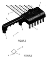
- Figure 1 shows a device 1 for strain relief connection at least one Cable 2, which has at least one electrical conductor 3.
- the cable 2 is it is preferably a round cable in which the outer sheath (outer sheath) consists of plastic and the electrical conductor 3, preferably a copper wire, surrounds.
- the device 1 is also on other types of cable (for Example flat cable or cable, within the outer shell of which several electrical Heads are arranged) applicable.
- a strain-relieving element 4 made of plastic is provided, which in the end area of the several cables running side by side and parallel 2 is arranged.
- This strain relief element 4 is made by a spraying process manufactured, in which the cable 2 inserted into an appropriate shape and with Overmoulded plastic. Because both the strain relief element and the Outer sheath of the at least one cable 2 made of plastic, they go intimate connection, so that the at least one cable 2 fixed in position in the strain relief Element 4 is set.
- the strain-relieving element 4 from an upper area 5, in which at least a cable 2 is set.
- the ends protrude from the underside of the upper area 5 the cable 2 with their exposed electrical conductors 3 out.
- the strain relief element 4 has a lower region 6, which is approximately web-shaped is trained.
- At least on the underside of the lower area 6 a positioning pin 7, wherein advantageously to fix the position of the strain relief Element 4 on the contact partner, not shown, at least two Positioning pins are available.
- These positioning pins 7 engage in corresponding ones Openings in the contact partner, for example in the case of a printed circuit board the opening is designed as a bore.
- the strain relief element 4 By engaging the positioning pins 7 in corresponding openings, the strain relief element 4 depending on their Design detachable or non-detachable with the contact partner, in particular the circuit board, connected so that the tensile or compressive forces acting on the cable 2 the strain relief element 4 are intercepted and no longer on the End region of the electrical conductor 3, in which the electrical connection is present is impact.
- the positioning pins 7 have a angular, in particular a triangular cross-section. These triangular ones Positioning pins 7 are then in a smaller diameter in the hole Printed circuit board so that all sharp edges of the positioning pins 7 in the Press the circuit board (circuit board) together and become somewhat blunt and yourself adjust it to the round contour of the hole.
- the strain relief element 4 can only be dismantled upwards away from the circuit board be, this upward movement through an appropriate lid can be prevented.
- strain-relieving element 4 Another advantage of the strain-relieving element 4 is that after Overmolding the cable 2 with plastic several cables 2 fixed in parallel next to each other are, so that the end regions of the electrical conductors by this position fixation 3 are arranged in a predeterminable grid (spacing from one another). So that can several cables 2 are arranged next to one another for easier assembly and thus be pre-assembled, with which the handling and assembly of several electrical Connections is simplified.
- the cables 2 are arranged approximately at a right angle, as an alternative to this, it is also conceivable that the cable 2 straight from the lead out strain relief element 4. In such a case, for example only the upper area 5 of the strain relief element 4 is present and the Positioning pins 7 on the face of the upper area 5 next to or between the cables 2 arranged.
- an arm 8 can also be injection molded onto the strain relief element 4, at the end of which there is also a positioning pin 7 and which points downwards has directed recesses 9, the contours of additional cables correspond.
- This arm 8 with its recesses 9 can not cables shown are routed on the circuit board.
- Figure 2 shows the device 1 for cable strain relief in plan view represents, which can also be seen in this view that several cables 2nd can be set next to each other by the strain relief element 4, so that through this pre-assembly, the assembly and manufacture of several side by side arranged electrical connections is simplified.
- FIG. 3 shows a positioning pin with a different cross section than that in the figures 1 and 2 was shown.
- the positioning pin 7 was shown in particular in FIG shown that it has an approximately triangular cross-section, the individual Side surfaces of the triangle have collapsed or may have collapsed.
- the positioning pin 7 shown in FIG. 3 consists of a pin body 10.
- this pin body 10 has a round cross section on.
- Longitudinally designed pin tabs are on the surface of the pin body 10 11 attached, which has a triangular shape in a particularly advantageous manner (or another) cross section.
- a possible application example for the device 1 according to the invention is in RF cables, power supply and ground cables for antenna amplifiers for vehicles, especially given passenger cars.
- strain relief element too can consist of two or more parts.
Landscapes
- Multi-Conductor Connections (AREA)
- Details Of Connecting Devices For Male And Female Coupling (AREA)
Applications Claiming Priority (2)
| Application Number | Priority Date | Filing Date | Title |
|---|---|---|---|
| DE10241650 | 2002-09-09 | ||
| DE10241650 | 2002-09-09 |
Publications (1)
| Publication Number | Publication Date |
|---|---|
| EP1396909A1 true EP1396909A1 (fr) | 2004-03-10 |
Family
ID=31502490
Family Applications (1)
| Application Number | Title | Priority Date | Filing Date |
|---|---|---|---|
| EP03020316A Withdrawn EP1396909A1 (fr) | 2002-09-09 | 2003-09-09 | Serre câble |
Country Status (2)
| Country | Link |
|---|---|
| US (1) | US6951475B2 (fr) |
| EP (1) | EP1396909A1 (fr) |
Cited By (1)
| Publication number | Priority date | Publication date | Assignee | Title |
|---|---|---|---|---|
| EP1791218A2 (fr) | 2005-11-23 | 2007-05-30 | Panta GmbH | Connecteur électrique |
Families Citing this family (3)
| Publication number | Priority date | Publication date | Assignee | Title |
|---|---|---|---|---|
| US7618280B2 (en) * | 2007-10-10 | 2009-11-17 | Tyco Electronics Corporation | Wire clamp system for an electrical connector |
| EP2950400B1 (fr) * | 2014-05-30 | 2016-04-27 | MD Elektronik GmbH | Câble multi-fils et procédé de fabrication d'un câble multi-fils |
| CN222127070U (zh) | 2021-11-19 | 2024-12-06 | 科尔莫根公司 | 应变消除插头、电动马达以及用于电动马达的印刷电路板 |
Citations (12)
| Publication number | Priority date | Publication date | Assignee | Title |
|---|---|---|---|---|
| DE2340314A1 (de) | 1973-08-09 | 1975-02-20 | Bosch Gmbh Robert | Zugentlastete kabeldurchfuehrung durch eine wand von elektrischen geraeten |
| EP0533729A1 (fr) * | 1990-06-13 | 1993-03-31 | Kaercher Gmbh & Co Alfred | Dispositif de decharge de traction de cable. |
| DE4201390A1 (de) | 1992-01-21 | 1993-07-22 | Philips Patentverwaltung | Anschlussstecker fuer ein mehradriges kabel |
| GB2268003A (en) * | 1992-06-04 | 1993-12-22 | Cannon Electric Gmbh | Device for attaching a connector to a printed circuit board |
| DE4441829A1 (de) | 1994-11-24 | 1996-05-30 | Murrelektronik Meg Gmbh & Co K | Elektrischer Verbinder |
| DE19614697C1 (de) | 1996-04-13 | 1997-08-28 | Provertha Steckverbinder Gmbh | Steckverbinder, insbesondere zur Kontaktierung einer Leiterplatte |
| US5667390A (en) * | 1995-03-06 | 1997-09-16 | Hon Hai Precision Ind. Co., Ltd. | I/O card and its associated cable harness assembly |
| EP0841723A2 (fr) | 1996-11-07 | 1998-05-13 | Peter Schön | Connecteur de câble et connexion en deux parties comprenant un tel connecteur |
| US6065993A (en) * | 1997-11-26 | 2000-05-23 | Hon Hai Precision Ind. Co., Ltd. | Cable connector assembly |
| US6254421B1 (en) * | 1998-06-29 | 2001-07-03 | The Whitaker Corporation | Connector assembly having pivoting wire carrier with position detents |
| DE20022774U1 (de) * | 2000-12-27 | 2002-04-04 | Continental ISAD Electronic Systems GmbH & Co. oHG, 86899 Landsberg | Kabel mit Anschlußelement |
| US20020072275A1 (en) | 1998-09-11 | 2002-06-13 | Junichi Arai | Connector socket, connector plug and connector assembly |
Family Cites Families (11)
| Publication number | Priority date | Publication date | Assignee | Title |
|---|---|---|---|---|
| US3795885A (en) * | 1972-02-08 | 1974-03-05 | Amp Inc | Adaptor for connecting flat conductor cable |
| US4068912A (en) * | 1977-02-25 | 1978-01-17 | Amp Incorporated | Cable clamping insulation displacing electrical connector for multi-conductor flat flexible cable |
| DE3405126C2 (de) | 1984-02-14 | 1985-12-05 | Philips Patentverwaltung Gmbh, 2000 Hamburg | Zugentlastungsaufsatz für Mehrfach-, insbesondere Flachbandkabel |
| US4715827A (en) * | 1985-04-30 | 1987-12-29 | Amp Incorporated | Modular connector system |
| US4668039A (en) * | 1985-12-16 | 1987-05-26 | Amp Incorporated | Connector for flat cable |
| DE3644025A1 (de) | 1986-12-22 | 1988-06-30 | Siemens Ag | Steckeinrichtung fuer ein verbindungskabel |
| US5118306A (en) * | 1991-05-29 | 1992-06-02 | Molex Incorporated | Multi-conductor electrical connector |
| EP0608222B1 (fr) | 1991-10-15 | 1995-12-20 | Itt Industries, Inc. | Dispositif de connexion maintenu par des chevilles |
| US5245683A (en) | 1992-08-21 | 1993-09-14 | Molex Incorporated | Board mounted fiber optic connector |
| DE4229778A1 (de) | 1992-09-05 | 1994-03-10 | Blaupunkt Werke Gmbh | Leiterbahnen aufweisende flexible Isolierstoffolie mit einem Zugentlastungsteil |
| US5338221A (en) * | 1993-06-09 | 1994-08-16 | Molex Incorporated | Electrical connector for high density ribbon cable |
-
2003
- 2003-09-08 US US10/656,108 patent/US6951475B2/en not_active Expired - Lifetime
- 2003-09-09 EP EP03020316A patent/EP1396909A1/fr not_active Withdrawn
Patent Citations (14)
| Publication number | Priority date | Publication date | Assignee | Title |
|---|---|---|---|---|
| DE2340314A1 (de) | 1973-08-09 | 1975-02-20 | Bosch Gmbh Robert | Zugentlastete kabeldurchfuehrung durch eine wand von elektrischen geraeten |
| FR2240551A1 (en) * | 1973-08-09 | 1975-03-07 | Bosch Gmbh Robert | Grommet for securing cables passing through openings - is made by casting plastics bush around cables |
| EP0533729A1 (fr) * | 1990-06-13 | 1993-03-31 | Kaercher Gmbh & Co Alfred | Dispositif de decharge de traction de cable. |
| EP0533729B1 (fr) | 1990-06-13 | 1994-03-16 | Alfred Kärcher GmbH & Co. | Dispositif de decharge de traction de cable |
| DE4201390A1 (de) | 1992-01-21 | 1993-07-22 | Philips Patentverwaltung | Anschlussstecker fuer ein mehradriges kabel |
| GB2268003A (en) * | 1992-06-04 | 1993-12-22 | Cannon Electric Gmbh | Device for attaching a connector to a printed circuit board |
| DE4441829A1 (de) | 1994-11-24 | 1996-05-30 | Murrelektronik Meg Gmbh & Co K | Elektrischer Verbinder |
| US5667390A (en) * | 1995-03-06 | 1997-09-16 | Hon Hai Precision Ind. Co., Ltd. | I/O card and its associated cable harness assembly |
| DE19614697C1 (de) | 1996-04-13 | 1997-08-28 | Provertha Steckverbinder Gmbh | Steckverbinder, insbesondere zur Kontaktierung einer Leiterplatte |
| EP0841723A2 (fr) | 1996-11-07 | 1998-05-13 | Peter Schön | Connecteur de câble et connexion en deux parties comprenant un tel connecteur |
| US6065993A (en) * | 1997-11-26 | 2000-05-23 | Hon Hai Precision Ind. Co., Ltd. | Cable connector assembly |
| US6254421B1 (en) * | 1998-06-29 | 2001-07-03 | The Whitaker Corporation | Connector assembly having pivoting wire carrier with position detents |
| US20020072275A1 (en) | 1998-09-11 | 2002-06-13 | Junichi Arai | Connector socket, connector plug and connector assembly |
| DE20022774U1 (de) * | 2000-12-27 | 2002-04-04 | Continental ISAD Electronic Systems GmbH & Co. oHG, 86899 Landsberg | Kabel mit Anschlußelement |
Cited By (3)
| Publication number | Priority date | Publication date | Assignee | Title |
|---|---|---|---|---|
| EP1791218A2 (fr) | 2005-11-23 | 2007-05-30 | Panta GmbH | Connecteur électrique |
| DE102005056147A1 (de) * | 2005-11-23 | 2007-05-31 | Panta Gmbh | Elektrischer Verbinder |
| EP1791218A3 (fr) * | 2005-11-23 | 2007-10-17 | Panta GmbH | Connecteur électrique |
Also Published As
| Publication number | Publication date |
|---|---|
| US20040077211A1 (en) | 2004-04-22 |
| US6951475B2 (en) | 2005-10-04 |
Similar Documents
| Publication | Publication Date | Title |
|---|---|---|
| DE69306463T2 (de) | Elektrischer Flachbauverbinder | |
| DE69013582T2 (de) | Keilförmiger Sockel, befestigt an SPG-Substrat. | |
| DE2460704A1 (de) | Elektrischer kontakt | |
| DE112011100434T5 (de) | Sicherungseinheit | |
| DE102018210892B4 (de) | Steckverbindungselement für ein Kraftfahrzeug und Verfahren zum Herstellen eines solchen Steckverbindungselements | |
| DE4111054C2 (fr) | ||
| DE19832011B4 (de) | Flachbandleitung mit einem zum lösbaren Verbinden vorgesehenen Anschlußbereich | |
| DE102004020422A1 (de) | Pin zur lötfreien elektrischen Verbindung mit einer Leiterplatte, ein Einpresswerkzeug sowie Verfahren zur Herstellung einer lötfreien elektrischen Verbindung | |
| EP3981046B1 (fr) | Connecteur de carte de circuit imprimé modulaire | |
| DE69401046T2 (de) | Elektrischer Kleinmotor mit Anschlusseinrichtung | |
| DE20108985U1 (de) | Anschluß für Drähte | |
| EP0051130A1 (fr) | Connexion à douille coaxiale enfichable | |
| DE102012218433B4 (de) | Kontaktanordnung | |
| DE69410138T2 (de) | Elektrischer Verbinder mit programmierbarem Ein-/Ausgang | |
| DE19757938A1 (de) | Isolationskamm für Multikontaktstecker | |
| EP1396909A1 (fr) | Serre câble | |
| DE3784023T2 (de) | Elektrischer steckverbinder, der eine kombination individueller adapter und steckerstift-elemente als kontaktglied enthaelt. | |
| DE19525801C2 (de) | Vorrichtung zum elektrisch leitenden Verbinden von zwei elektrischen Leitungen | |
| WO2022189046A1 (fr) | Dispositif de connexion pour fixer des composants électroniques sur une carte de circuit imprimé | |
| EP1162694B1 (fr) | Appareil pour la connexion de conducteurs électriques | |
| DE102004014353B4 (de) | Kontaktträger für einen Multifunktionskontakt und Steckverbinder hierzu | |
| DE19532280A1 (de) | Anschlußvorrichtung zum codierbaren Anschließen elektrischer Verbraucher | |
| DE102012011047B4 (de) | Verbindungsbauteil und Schaltungsanordnung mit dem Verbindungsbauteil | |
| DE10359250B4 (de) | Steckverbinder, insbesondere zur Kontaktierung einer Leiterplatte | |
| DE69701219T2 (de) | Elektronische baugruppe mit einer an einer spule verbundenen elektronischen einheit |
Legal Events
| Date | Code | Title | Description |
|---|---|---|---|
| PUAI | Public reference made under article 153(3) epc to a published international application that has entered the european phase |
Free format text: ORIGINAL CODE: 0009012 |
|
| AK | Designated contracting states |
Kind code of ref document: A1 Designated state(s): AT BE BG CH CY CZ DE DK EE ES FI FR GB GR HU IE IT LI LU MC NL PT RO SE SI SK TR |
|
| AX | Request for extension of the european patent |
Extension state: AL LT LV MK |
|
| 17P | Request for examination filed |
Effective date: 20040327 |
|
| AKX | Designation fees paid |
Designated state(s): AT BE BG CH CY CZ DE DK EE ES FI FR GB GR HU IE IT LI LU MC NL PT RO SE SI SK TR |
|
| TPAC | Observations filed by third parties |
Free format text: ORIGINAL CODE: EPIDOSNTIPA |
|
| 17Q | First examination report despatched |
Effective date: 20110315 |
|
| RAP1 | Party data changed (applicant data changed or rights of an application transferred) |
Owner name: HIRSCHMANN CAR COMMUNICATION GMBH |
|
| STAA | Information on the status of an ep patent application or granted ep patent |
Free format text: STATUS: THE APPLICATION IS DEEMED TO BE WITHDRAWN |
|
| 18D | Application deemed to be withdrawn |
Effective date: 20170307 |