EP0534076A1 - Ensemble de verrouillage du type chiquet - Google Patents
Ensemble de verrouillage du type chiquet Download PDFInfo
- Publication number
- EP0534076A1 EP0534076A1 EP19920112285 EP92112285A EP0534076A1 EP 0534076 A1 EP0534076 A1 EP 0534076A1 EP 19920112285 EP19920112285 EP 19920112285 EP 92112285 A EP92112285 A EP 92112285A EP 0534076 A1 EP0534076 A1 EP 0534076A1
- Authority
- EP
- European Patent Office
- Prior art keywords
- latch
- pivotal pin
- pawl lever
- latch member
- engagement
- Prior art date
- Legal status (The legal status is an assumption and is not a legal conclusion. Google has not performed a legal analysis and makes no representation as to the accuracy of the status listed.)
- Withdrawn
Links
Images

Classifications
-
- E—FIXED CONSTRUCTIONS
- E05—LOCKS; KEYS; WINDOW OR DOOR FITTINGS; SAFES
- E05C—BOLTS OR FASTENING DEVICES FOR WINGS, SPECIALLY FOR DOORS OR WINDOWS
- E05C3/00—Fastening devices with bolts moving pivotally or rotatively
- E05C3/12—Fastening devices with bolts moving pivotally or rotatively with latching action
- E05C3/16—Fastening devices with bolts moving pivotally or rotatively with latching action with operating handle or equivalent member moving otherwise than rigidly with the latch
- E05C3/22—Fastening devices with bolts moving pivotally or rotatively with latching action with operating handle or equivalent member moving otherwise than rigidly with the latch the bolt being spring controlled
- E05C3/24—Fastening devices with bolts moving pivotally or rotatively with latching action with operating handle or equivalent member moving otherwise than rigidly with the latch the bolt being spring controlled in the form of a bifurcated member
-
- E—FIXED CONSTRUCTIONS
- E05—LOCKS; KEYS; WINDOW OR DOOR FITTINGS; SAFES
- E05B—LOCKS; ACCESSORIES THEREFOR; HANDCUFFS
- E05B5/00—Handles completely let into the surface of the wing
-
- E—FIXED CONSTRUCTIONS
- E05—LOCKS; KEYS; WINDOW OR DOOR FITTINGS; SAFES
- E05B—LOCKS; ACCESSORIES THEREFOR; HANDCUFFS
- E05B15/00—Other details of locks; Parts for engagement by bolts of fastening devices
- E05B15/0046—Ratchet mechanisms
-
- Y—GENERAL TAGGING OF NEW TECHNOLOGICAL DEVELOPMENTS; GENERAL TAGGING OF CROSS-SECTIONAL TECHNOLOGIES SPANNING OVER SEVERAL SECTIONS OF THE IPC; TECHNICAL SUBJECTS COVERED BY FORMER USPC CROSS-REFERENCE ART COLLECTIONS [XRACs] AND DIGESTS
- Y10—TECHNICAL SUBJECTS COVERED BY FORMER USPC
- Y10S—TECHNICAL SUBJECTS COVERED BY FORMER USPC CROSS-REFERENCE ART COLLECTIONS [XRACs] AND DIGESTS
- Y10S292/00—Closure fasteners
- Y10S292/31—Lever operator, flush
-
- Y—GENERAL TAGGING OF NEW TECHNOLOGICAL DEVELOPMENTS; GENERAL TAGGING OF CROSS-SECTIONAL TECHNOLOGIES SPANNING OVER SEVERAL SECTIONS OF THE IPC; TECHNICAL SUBJECTS COVERED BY FORMER USPC CROSS-REFERENCE ART COLLECTIONS [XRACs] AND DIGESTS
- Y10—TECHNICAL SUBJECTS COVERED BY FORMER USPC
- Y10S—TECHNICAL SUBJECTS COVERED BY FORMER USPC CROSS-REFERENCE ART COLLECTIONS [XRACs] AND DIGESTS
- Y10S292/00—Closure fasteners
- Y10S292/43—Rear deck lid latches
-
- Y—GENERAL TAGGING OF NEW TECHNOLOGICAL DEVELOPMENTS; GENERAL TAGGING OF CROSS-SECTIONAL TECHNOLOGIES SPANNING OVER SEVERAL SECTIONS OF THE IPC; TECHNICAL SUBJECTS COVERED BY FORMER USPC CROSS-REFERENCE ART COLLECTIONS [XRACs] AND DIGESTS
- Y10—TECHNICAL SUBJECTS COVERED BY FORMER USPC
- Y10T—TECHNICAL SUBJECTS COVERED BY FORMER US CLASSIFICATION
- Y10T292/00—Closure fasteners
- Y10T292/08—Bolts
- Y10T292/1043—Swinging
- Y10T292/1044—Multiple head
- Y10T292/1045—Operating means
- Y10T292/1047—Closure
Definitions
- This invention relates to a latch assembly for locking a closing member such as a door or a lid to a box-like body or like stationary frame.
- Japanese Utility Model Publication No. 157,864/1989 discloses a latch assembly which comprises a latch case secured to a closing member and having a front plate member, bearing arm means projecting from the front plate member, a latch member pivoted by a pivotal pin to the bearing arm means and having on one side a guide projection for engagement and disengagement with respect to a lockable member on the side of a stationary frame, the guide projection having a stem portion thereof formed with a locking recess extending toward the pivotal pin, the lockable member being engaged and disengaged with respect to the locking recess, the latch member being provided on the side opposite the guide projection with an engagement projection, and a lock lever pivoted by a separate pivotal pin to the bearing arm means and having a free end provided with a lock projection for engagement and disengagement with respect to the engagement projection of the latch member, the latch member being rotationally urged toward an unlocked position by a torsion spring having a coil portion fitted on the pivotal pin, the lock lever rotationally urged by a separate torsion spring
- the guide projection of the latch member is brought into contact with the lockable member of the stationary frame, and during further closing of the closing member the latch member urged by the lockable member is rotated about the pivotal pin.
- the lock projection of the lock lever is engaged with the engagement projection of the latch member, thus locking the closing member to the stationary frame.
- the latch member is provided with a single engagement projection. Therefore, the rotational angle of the latch member from the waiting position to the lock position is fixed.
- An object of the invention is to provide a ratchet assembly, with which a closing member can be reliably locked to a stationary frame even if the relative positions of the lockable member and latch member are shifted due to some cause.
- a ratchet type latch assembly which comprises a latch case secured to a closing member and having a front plate member, a pair of bearing arms projecting from the rear surface of the front plate member, a latch member pivoted by a pivotal pin to rear end projections of said bearing arms, the latch member having on one side thereof a guide projection for engagement and disengagement with respect to a lockable member on the side of a stationary frame, said guide projection having a stem portion thereof formed with a locking recess extending toward the pivotal pin, the lockable member being engaged in and disengaged from the recess, the latch member having an arcuate edge formed on the side opposite the guide projection and about the pivotal pin, the arcuate edge being formed with a plurality of ratchets, a pawl lever having an intermediate portion pivoted by a pivotal pin to central portions of the bearing arms, the pawl lever having a rear end portion thereof formed with a check pawl for engagement and disengagement with respect
- the rotational angle, for which the latch member is rotated from the waiting position to the lock position has a fixed redundancy corresponding to the circumferential dimension of the ratchet train.
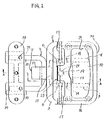
- FIG. 1 illustrates an embodiment of the ratchet type latch assembly according to the invention.
- a latch case 2 which has a front plate member 3.
- a pair of bearing arms 4 and 5 project from the rear surface of the front plate member 3.
- a latch member 7 is pivoted by a pivotal pin 6 to rear end portions of the bearing arms 4 and 5.
- the latch member 7 has on one side thereof a guide projection 10 for engagement and disengagement with respect to a lockable member 9 on one side of a stationary frame 8.
- the guide projection 10 has a stem portion thereof formed with a latching recess 11 extending toward the pivotal pin 6.
- the lockable member 9 is engaged in and disengaged from the locking recess.
- the latch member 7 has an arcuate edge formed on the side opposite the guide projection 10 and about the pivotal pin 6.
- the arcuate edge is formed with a plurality of ratchets 12.
- a pawl lever 13 has an intermediate portion pivoted by a pivotal pin 14 to central portions of the bearing arms 4 and 5.
- the pawl lever 13 has its rear end portion formed with a check pawl 15 for engagement and disengagement with respect to the ratchet 12.
- Pivoted by a pivotal pin 17 to the front plate member 3 of the latch case 2 is a stem portion 17 of an operating handle 16.
- the front plate member 3 has on its rear side a hollow cylindrical portion 18.
- a connecting rod 19 is inserted in the hollow cylindrical portion 18 and biased forwardly by a compression spring 20.
- the connecting rod 19 has a driven front end portion 22 projecting from the front end portion 21 of the hollow cylindrical portion 18 and in contact with a driven stem portion 23 of the operating handle 16.
- the connecting rod 19 has a drive rear end portion 25 projecting from the rear end opening 24 of the hollow cylindrical portion 18 and in contact with a driven front end projection 26 of the pawl lever.
- a coil member 28 is fitted on the pivotal pin 6.
- the check pawl 15 of the pawl lever 13 is urged against the ratchets 12 of the latch member by a torsional spring 27 having one straight end portion 29 in engagement with the guide projection 10 of the latch member 7 and the other straight end portion 30 in engagement with the driven front end projection 26 of the pawl lever 13.
- the latch case 2 is secured to the closing member 1 with its front plate member 3 disposed on the front side of the closing member 1, and the pair of, i.e., upper and lower, bearing arms 4 and 5 project from the rear surface of the closing member 1 at right angles thereto.
- the pivotal pin 6 of the latch member 7 and pivotal pin 14 of the pawl lever 13 extend parallel to each other and across the bearing arms 4 and 5.
- the hollow cylindrical portion 18 is made integral with the front plate member 3, and is located between the bearing arms 4 and 5 nearer the left end of the front plate member 3.
- a right half portion of the front plate member 3 has a raised portion 32 which is inserted in a finger insertion hole 31 of the operating handle 16 when the handle 16 is turned down. When the operating handle 16 is in its turned-down state, its end portion 33 projects from the right end 34 of the front plate member 3, thus facilitating the hooking of a finger on the operating handle 16 when erecting the same.
- the compression coil spring 20 is interposed between a rear end wall 35 of the hollow cylindrical portion 18 and an outer peripheral flange 36 of the connecting rod 19, and the drive stem portion 23 of the operating handle 16 projects leftward from the pair, i.e., upper and lower, pivotal pins 17.
- the drive pins 17 extend parallel to the pivotal pins 6 and 14.
- the lockable member 9 is a U-shaped rod, and after the insertion of its opposite legs 37 in a left and a right hole 39 of a holder 38 and the adjustment of the length of the projecting portions of the legs 37, it is secured to the holder 38 by a stud 40 and a nut 41.
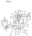
- the latch member 7 has a stopper shoulder 42 formed adjacent the ratchet train 12. When the latch member 7 is rotated to its released set position, a stopper face 43 of the pawl lever 13 at the rear end thereof is brought into contact with the stopper shoulder 42, thus holding the latch member 7 at a waiting position thereof.
- the latch member 7 is pivoted by the pivotal pin 6 to the rear end portions of the bearing arms 4 and 5 of the latch case 2, the pawl lever 13 is pivoted by the pivotal pins 14 to central portions of the bearing arms 4 and 5, the latchet member 7 has its arcuate edge, which is formed on the side of the pivotal pin 6 opposite the guide projection 10, formed with a plurality of ratchets 12, and the pawl lever 13 has its rear end portion provided with the check pawl 15 for engagement and disengagement with respect to the ratchet train 12.
- the rotational angle, through which the latch member is rotated from the waiting position to the lock position, is a fixed redundancy corresponding to the circumferential dimension of the ratchet train 12.
Landscapes
- Engineering & Computer Science (AREA)
- Mechanical Engineering (AREA)
- Lock And Its Accessories (AREA)
- Ladders (AREA)
Applications Claiming Priority (2)
| Application Number | Priority Date | Filing Date | Title |
|---|---|---|---|
| JP27485491A JP2870611B2 (ja) | 1991-09-26 | 1991-09-26 | ラチェット型ラッチ装置 |
| JP274854/91 | 1991-09-26 |
Publications (1)
| Publication Number | Publication Date |
|---|---|
| EP0534076A1 true EP0534076A1 (fr) | 1993-03-31 |
Family
ID=17547503
Family Applications (1)
| Application Number | Title | Priority Date | Filing Date |
|---|---|---|---|
| EP19920112285 Withdrawn EP0534076A1 (fr) | 1991-09-26 | 1992-07-17 | Ensemble de verrouillage du type chiquet |
Country Status (4)
| Country | Link |
|---|---|
| US (1) | US5234238A (fr) |
| EP (1) | EP0534076A1 (fr) |
| JP (1) | JP2870611B2 (fr) |
| KR (1) | KR0135413B1 (fr) |
Cited By (6)
| Publication number | Priority date | Publication date | Assignee | Title |
|---|---|---|---|---|
| WO1998004800A1 (fr) * | 1996-07-26 | 1998-02-05 | Robert Bosch Gmbh | Serrure de portiere, de capot d'automobile, ou analogue |
| FR2753224A1 (fr) * | 1996-09-10 | 1998-03-13 | Jeambrun Appareillages | Serrure electromagnetique pour porte a ouverture telecommandee |
| WO2005012677A1 (fr) * | 2003-07-18 | 2005-02-10 | Intier Automotive Closures S.P.A. | Serrure pour portiere de vehicule a moteur |
| RU2382862C1 (ru) * | 2008-09-18 | 2010-02-27 | Открытое акционерное общество "Производственная фирма КМТ - Ломоносовский опытный завод" (ОАО "ПФ "КМТ") | Запирающее устройство двери |
| DE112005001560B4 (de) * | 2004-06-30 | 2014-04-03 | Southco, Inc. | Bodenklappenverschluß |
| EP2602411A3 (fr) * | 2011-12-08 | 2017-03-22 | MACO Technologie GmbH | Agencement de ferrure |
Families Citing this family (42)
| Publication number | Priority date | Publication date | Assignee | Title |
|---|---|---|---|---|
| US5484176A (en) * | 1994-05-20 | 1996-01-16 | Motus, Inc. | Latch mechanism |
| US5787643A (en) * | 1995-10-03 | 1998-08-04 | Excel Industries, Ltd. | Window with latch assembly |
| US6048006A (en) * | 1997-09-12 | 2000-04-11 | Southco, Inc. | Ratcheting pawl latch |
| US5927772A (en) * | 1997-09-12 | 1999-07-27 | Southco, Inc. | Ratcheting pawl latch |
| US6000737A (en) * | 1997-09-17 | 1999-12-14 | Atoma International Corp. | Loop striker |
| WO2001046543A2 (fr) * | 1999-12-20 | 2001-06-28 | Southco, Inc. | Loquet a cliquet |
| EP1264062A4 (fr) | 2000-03-07 | 2004-04-07 | Southco | Verrou sensible a la gravite |
| KR20030038657A (ko) | 2000-07-07 | 2003-05-16 | 사우스코 인코포레이티드 | 전기작동식 래칫 폴 래치 |
| US6390518B1 (en) * | 2000-08-15 | 2002-05-21 | Maytag Corporation | Latching mechanism for an appliance door |
| US6460902B1 (en) * | 2000-10-27 | 2002-10-08 | Pompanette, Inc. | Slam latch and hatch assembly including a slam latch |
| EP1330584B1 (fr) * | 2000-11-01 | 2014-06-11 | Southco, Inc. | Dispositif de verrouillage |
| US6893061B2 (en) * | 2001-08-09 | 2005-05-17 | General Electric Company | Methods and apparatus for securing a dishwasher door |
| US7185927B2 (en) * | 2002-04-07 | 2007-03-06 | Southco, Inc. | Glovebox latch |
| US7097219B2 (en) * | 2002-05-03 | 2006-08-29 | Anchor Tool & Die Company | Encapsulated striker assembly |
| US6883842B2 (en) * | 2002-12-19 | 2005-04-26 | Anchor Tool & Die Company | Latch strikers with mechanically locked components |
| US7313937B2 (en) * | 2004-02-22 | 2008-01-01 | Southco, Inc. | Latch |
| USD506120S1 (en) | 2004-02-22 | 2005-06-14 | Southco, Inc. | Multi-directional rotary-pawl latch |
| US7798540B1 (en) * | 2004-06-30 | 2010-09-21 | Southco, Inc. | Load-floor latch |
| US7269984B2 (en) * | 2004-07-31 | 2007-09-18 | Southco, Inc. | Ratcheting pawl latch |
| US7255053B2 (en) * | 2004-08-13 | 2007-08-14 | Wood Manufacturing Company | Boat deck locker |
| US20060208495A1 (en) * | 2005-03-05 | 2006-09-21 | Robin Talukdar | Glove box latch |
| DE102007012616A1 (de) * | 2006-03-16 | 2007-10-31 | Southco, Inc. | Drehklinkenverriegelung für ein Handschuhfach |
| US20070241570A1 (en) * | 2006-04-03 | 2007-10-18 | Paskonis Almantas K | Latch and latch striker interface improvements |
| JP2007291688A (ja) * | 2006-04-24 | 2007-11-08 | Sankyo Tateyama Aluminium Inc | 建築物用仮ロック機能付き扉装置 |
| USD582250S1 (en) | 2006-10-31 | 2008-12-09 | Southco, Inc. | Latch |
| WO2008055246A2 (fr) * | 2006-10-31 | 2008-05-08 | Southco, Inc. | Loquet |
| DE202006019165U1 (de) * | 2006-12-20 | 2008-05-08 | S-Fasteners Gmbh | Anordnung mit einem Verriegelungs-Element für einen Verriegelungshaken |
| JP5309009B2 (ja) * | 2009-12-15 | 2013-10-09 | 株式会社栃木屋 | ラッチ装置 |
| US20110215596A1 (en) * | 2010-03-03 | 2011-09-08 | Decrane Aerospace, Inc. | Cabinet latch |
| US8752871B2 (en) * | 2011-07-21 | 2014-06-17 | Actron Manufacturing, Inc. | Wire strike assembly |
| US8720237B2 (en) * | 2011-10-19 | 2014-05-13 | Daws Manufacturing Company, Inc. | Rotary latch |
| ITRM20120055A1 (it) * | 2012-02-20 | 2013-08-21 | Bitron Spa | Dispositivo blocco-porta per un portello di un elettrodomestico. |
| US20130257065A1 (en) * | 2012-03-29 | 2013-10-03 | B/E Aerospace, Inc. | Cart bay door paddle latch |
| US9322192B2 (en) | 2012-03-29 | 2016-04-26 | B/E Aerospace, Inc. | Aircraft galley latches and sealing system |
| CN103813678B (zh) * | 2012-11-05 | 2016-05-25 | 华为技术有限公司 | 锁紧装置 |
| US9328543B2 (en) | 2012-11-29 | 2016-05-03 | B/E Aerospace, Inc. | Galley cart bay door latch |
| US9175505B2 (en) * | 2013-02-06 | 2015-11-03 | Honda Motor Co., Ltd. | Door handle assemblies and vehicles having same |
| US9260890B2 (en) | 2014-05-13 | 2016-02-16 | Daws Manufacturing Co., Inc. | Latch mechanism |
| EP3670327A1 (fr) * | 2018-12-19 | 2020-06-24 | Bombardier Inc. | Ensemble de poignée de porte d'aéronef |
| EP3883753A4 (fr) | 2019-04-29 | 2022-09-28 | Hewlett-Packard Development Company, L.P. | Unité de refroidissement dotée d'un mécanisme de verrouillage automatique |
| CN110578433B (zh) * | 2019-09-29 | 2024-05-10 | 金湖县微晶控制系统有限公司 | 上锁机构 |
| EP4036354A4 (fr) * | 2020-06-01 | 2023-11-29 | Jamco Corporation | Fixation de bouton de verrouillage, porte de toilettes et procédé de montage de fixation de bouton de verrouillage |
Citations (3)
| Publication number | Priority date | Publication date | Assignee | Title |
|---|---|---|---|---|
| US2676047A (en) * | 1951-08-31 | 1954-04-20 | Wayne C Harrigan | Door latch mechanism |
| US3153553A (en) * | 1961-09-27 | 1964-10-20 | Gen Motors Corp | Flush type door handles |
| US4635454A (en) * | 1984-11-19 | 1987-01-13 | Avis Industrial Corporation | Latch gear lock assembly |
Family Cites Families (11)
| Publication number | Priority date | Publication date | Assignee | Title |
|---|---|---|---|---|
| US2243772A (en) * | 1937-10-30 | 1941-05-27 | Philco Corp | Latching means for refrigerator doors |
| US2767007A (en) * | 1953-06-22 | 1956-10-16 | Nat Lock Co | Refrigerator latch |
| US3697105A (en) * | 1969-12-24 | 1972-10-10 | Atwood Vacuum Machine Co | Latch for vehicle doors |
| US3664698A (en) * | 1970-04-02 | 1972-05-23 | Prod Design & Mfg | Electric actuating mechanism |
| US3695659A (en) * | 1970-07-27 | 1972-10-03 | Gen Motors Corp | Hood latch assembly |
| DE2308860A1 (de) * | 1972-03-02 | 1973-09-27 | Nissan Motor | Vorrichtung zum verschliessen eines gepaeckraumes bei einem kraftfahrzeug |
| US4220364A (en) * | 1978-03-01 | 1980-09-02 | Hartwell Corporation | Flush type latches |
| US4209194A (en) * | 1978-06-05 | 1980-06-24 | Hartwell Corporation | Keeper for rotary latches |
| JPS57125882A (en) * | 1981-01-30 | 1982-08-05 | Tokyo Shibaura Electric Co | Device for recording control rod position detection |
| JPS59126876A (ja) * | 1982-12-30 | 1984-07-21 | アイシン精機株式会社 | 自動車用ドアハンドル装置 |
| JPH01157864A (ja) * | 1987-12-15 | 1989-06-21 | Tokyo Electric Co Ltd | 印字装置のドットヘッド駆動回路 |
-
1991
- 1991-09-26 JP JP27485491A patent/JP2870611B2/ja not_active Expired - Lifetime
-
1992
- 1992-06-29 US US07/905,763 patent/US5234238A/en not_active Expired - Lifetime
- 1992-07-03 KR KR92011879A patent/KR0135413B1/ko not_active Expired - Lifetime
- 1992-07-17 EP EP19920112285 patent/EP0534076A1/fr not_active Withdrawn
Patent Citations (3)
| Publication number | Priority date | Publication date | Assignee | Title |
|---|---|---|---|---|
| US2676047A (en) * | 1951-08-31 | 1954-04-20 | Wayne C Harrigan | Door latch mechanism |
| US3153553A (en) * | 1961-09-27 | 1964-10-20 | Gen Motors Corp | Flush type door handles |
| US4635454A (en) * | 1984-11-19 | 1987-01-13 | Avis Industrial Corporation | Latch gear lock assembly |
Cited By (8)
| Publication number | Priority date | Publication date | Assignee | Title |
|---|---|---|---|---|
| WO1998004800A1 (fr) * | 1996-07-26 | 1998-02-05 | Robert Bosch Gmbh | Serrure de portiere, de capot d'automobile, ou analogue |
| US6113161A (en) * | 1996-07-26 | 2000-09-05 | Robert Bosch Gmbh | Motor vehicle door lock, bonnet lock or the like |
| FR2753224A1 (fr) * | 1996-09-10 | 1998-03-13 | Jeambrun Appareillages | Serrure electromagnetique pour porte a ouverture telecommandee |
| WO2005012677A1 (fr) * | 2003-07-18 | 2005-02-10 | Intier Automotive Closures S.P.A. | Serrure pour portiere de vehicule a moteur |
| US7475922B2 (en) | 2003-07-18 | 2009-01-13 | Intier Automotive Closures S.P.A. | Lock for a door of a motor vehicle |
| DE112005001560B4 (de) * | 2004-06-30 | 2014-04-03 | Southco, Inc. | Bodenklappenverschluß |
| RU2382862C1 (ru) * | 2008-09-18 | 2010-02-27 | Открытое акционерное общество "Производственная фирма КМТ - Ломоносовский опытный завод" (ОАО "ПФ "КМТ") | Запирающее устройство двери |
| EP2602411A3 (fr) * | 2011-12-08 | 2017-03-22 | MACO Technologie GmbH | Agencement de ferrure |
Also Published As
| Publication number | Publication date |
|---|---|
| KR0135413B1 (en) | 1998-05-15 |
| KR930006283A (ko) | 1993-04-21 |
| JPH0586764A (ja) | 1993-04-06 |
| US5234238A (en) | 1993-08-10 |
| JP2870611B2 (ja) | 1999-03-17 |
Similar Documents
| Publication | Publication Date | Title |
|---|---|---|
| EP0534076A1 (fr) | Ensemble de verrouillage du type chiquet | |
| JPS62174482A (ja) | 引つ張りラツチ組立体 | |
| JP2524952B2 (ja) | 扉用ロックハンドル装置 | |
| US4486041A (en) | Door handle unit | |
| KR100407094B1 (ko) | 가방의자물쇠장치 | |
| JPH05133161A (ja) | 掛止・施錠機構 | |
| JP4122598B2 (ja) | 遮断器 | |
| JPH11141207A (ja) | ラッチ錠 | |
| JPH0310294Y2 (fr) | ||
| JPS6227649Y2 (fr) | ||
| JP2504717B2 (ja) | ロック金具 | |
| JPH049821Y2 (fr) | ||
| JP4514076B2 (ja) | 鎌錠 | |
| JPH11159212A (ja) | 車両用ドアロック装置 | |
| JP2840219B2 (ja) | 迅速開放型扉用ロックハンドル装置 | |
| JPH0720301Y2 (ja) | 退没位置拘束型引き戸用ロック装置 | |
| JPH068226Y2 (ja) | 自動車のバックドアラッチ装置 | |
| JPH10299309A (ja) | トリガー機構付き扉用ロック装置 | |
| JPH0643400Y2 (ja) | 押下げ解錠型平面ハンドル装置 | |
| JPH06100040B2 (ja) | 着脱式側部ウインド開閉装置のロック装置 | |
| JPH07100988B2 (ja) | 錠 前 | |
| JPH0932380A (ja) | 引戸用ラッチ付き引手 | |
| JPH06275964A (ja) | 蓋の開閉装置 | |
| JPH0732152U (ja) | 馬蹄錠 | |
| JPH06307145A (ja) | プラスチック製扉係止装置 |
Legal Events
| Date | Code | Title | Description |
|---|---|---|---|
| PUAI | Public reference made under article 153(3) epc to a published international application that has entered the european phase |
Free format text: ORIGINAL CODE: 0009012 |
|
| AK | Designated contracting states |
Kind code of ref document: A1 Designated state(s): AT BE CH DE DK ES FR GB GR IT LI LU NL PT SE |
|
| 17P | Request for examination filed |
Effective date: 19930512 |
|
| 17Q | First examination report despatched |
Effective date: 19940621 |
|
| STAA | Information on the status of an ep patent application or granted ep patent |
Free format text: STATUS: THE APPLICATION IS DEEMED TO BE WITHDRAWN |
|
| 18D | Application deemed to be withdrawn |
Effective date: 19941103 |