EP0534096A2 - Procédé et dispositif pour examiner des impuretés dans des récipients - Google Patents
Procédé et dispositif pour examiner des impuretés dans des récipients Download PDFInfo
- Publication number
- EP0534096A2 EP0534096A2 EP92113169A EP92113169A EP0534096A2 EP 0534096 A2 EP0534096 A2 EP 0534096A2 EP 92113169 A EP92113169 A EP 92113169A EP 92113169 A EP92113169 A EP 92113169A EP 0534096 A2 EP0534096 A2 EP 0534096A2
- Authority
- EP
- European Patent Office
- Prior art keywords
- container
- cuvette
- gas
- containers
- measuring
- Prior art date
- Legal status (The legal status is an assumption and is not a legal conclusion. Google has not performed a legal analysis and makes no representation as to the accuracy of the status listed.)
- Granted
Links
Images


Classifications
-
- B—PERFORMING OPERATIONS; TRANSPORTING
- B08—CLEANING
- B08B—CLEANING IN GENERAL; PREVENTION OF FOULING IN GENERAL
- B08B9/00—Cleaning hollow articles by methods or apparatus specially adapted thereto
- B08B9/08—Cleaning containers, e.g. tanks
- B08B9/46—Inspecting cleaned containers for cleanliness
-
- G—PHYSICS
- G01—MEASURING; TESTING
- G01N—INVESTIGATING OR ANALYSING MATERIALS BY DETERMINING THEIR CHEMICAL OR PHYSICAL PROPERTIES
- G01N21/00—Investigating or analysing materials by the use of optical means, i.e. using sub-millimetre waves, infrared, visible or ultraviolet light
- G01N21/84—Systems specially adapted for particular applications
- G01N21/88—Investigating the presence of flaws or contamination
- G01N21/90—Investigating the presence of flaws or contamination in a container or its contents
- G01N21/9018—Dirt detection in containers
-
- G—PHYSICS
- G01—MEASURING; TESTING
- G01N—INVESTIGATING OR ANALYSING MATERIALS BY DETERMINING THEIR CHEMICAL OR PHYSICAL PROPERTIES
- G01N33/00—Investigating or analysing materials by specific methods not covered by groups G01N1/00 - G01N31/00
- G01N33/0078—Testing material properties on manufactured objects
- G01N33/0081—Containers; Packages; Bottles
-
- G—PHYSICS
- G01—MEASURING; TESTING
- G01N—INVESTIGATING OR ANALYSING MATERIALS BY DETERMINING THEIR CHEMICAL OR PHYSICAL PROPERTIES
- G01N15/00—Investigating characteristics of particles; Investigating permeability, pore-volume or surface-area of porous materials
- G01N2015/0007—Investigating dispersion of gas
- G01N2015/0011—Investigating dispersion of gas in liquids, e.g. bubbles
Definitions
- the invention relates to a method for examining containers for foreign substances, a gas sample being taken from the container and being examined, and a device for examining containers for foreign substances with a line leading from an opening of the container to a measuring cell and with a gas source.
- a generic method and a generic device are known from EP-A-306 307.
- the bottles are transported on a rotary conveyor and are connected at their top to ionization chambers, into which samples in the bottles of "newly formed steam" are “drawn”. This is done using conventional pumps, venturi devices or blowers with or without vacuum accumulators or cylinders. Sampling takes place here by suction. This is disadvantageous and in particular is not sufficiently effective.
- the ionization also involves destruction of the foreign gases to be examined, so that there is a risk that certain molecules as such are destroyed and thus only the fractions but not the starting gases can be determined.
- the invention has for its object to provide a method and an apparatus that enable a quick and extremely reliable inspection of containers, in particular the bottles mentioned, whether there are or are interfering foreign substances in them.
- the above-mentioned object is achieved in a method of the type mentioned at the outset by taking the gas sample in such a way that a standard gas, such as air, is blown into the container in order to expel the gas in the container into a measuring cuvette and so that the previously the container and is examined photometrically in the measuring cuvette from this gas escaping due to the excess pressure caused.
- a device according to the invention is characterized in that the gas source is a standard gas pressure source and that a pressure line leading from the standard gas pressure source into the container is provided in addition to the removal line leading from the containers.
- the removal of gas in the bottles according to EP-A-306 307 into the surroundings has nothing to do with the sampling according to the invention by means of excess pressure.
- the photometric examination can be carried out, for example, according to DE-A-23 40 747 or WO 81/02633, which also show suitable detector devices.
- the standard gas is blown in via a lance moved into the container and the escaping air is fed to the measuring cell via a further lance, the standard gas in particular being blown centrally into the containers.
- the walls of the container are heated at least before the standard gas is blown in.
- the compressed air or a compressed gas expelling the air in the container is blown in centrally, so that the exiting air first brushes along the walls of the container and absorbs gas particles from it, which may have previously been expelled by the heating, and conduct the analysis can.
- a heating station is provided for the containers and that the heating station has IR radiators.
- a cuvette is provided for receiving the air pushed out of a container and the air pushed out of the container can be brought into the detector device in the cuvette.
- the cuvette is provided with heating devices.
- the pressure line has a lance which can be inserted centrally into a container and is characterized by a cap provided with an annular seal, on the periphery of which a discharge line for air pressed out of the container opens, which leads to a measuring cuvette.
- the measuring cell is provided with sealed viewing windows on the end face.
- the measuring cell has a high level of tightness since it is sealed on all sides, the inlet cylinder and, if applicable, outlets being able to be completely sealed by valves.
- the cuvette is provided with rinsing outlets in which a valve is arranged.
- the measuring cell is open on both end faces and its end faces are guided closely past stationary ring walls arranged on the inside and outside.
- the ring walls are closed except for individual outlets over the entire circumference.
- a preferred development provides that rinsing outlets and, if appropriate, inlets for the measuring cuvette are provided at suitable locations in the stationary ring walls, namely where the gas sampling device for removing the measuring gas from the containers to be examined is located (in the path of movement the detector device) and where the measuring cuvettes are cleaned again by neutral purging gas from the measuring gas (in the path of movement immediately behind the detector devices).
- the purging air can be supplied via the supply inlet rotating with the cuvette (through which the measuring gas is also fed to the measuring cuvette) or through an inlet provided in a ring wall on one end of the measuring cuvette, while an outlet is only on the opposite end is arranged.
- These configurations have the advantage that separate valves can be dispensed with, since the end faces are automatically adequately closed when they are moved from the inlet and outlet regions in the walls to the closed regions of the surrounding walls.
- the gap between the open end faces of the measuring cell and the surrounding closed ring walls is only a few hundredths of a millimeter thick. It has been found that the loss of sample gas is negligible.
- containers such as PET bottles, gas bottles or other containers, for gaseous foreign substances in them, such as hair tonic, oils or the like, but also decomposition gases from small animals introduced into the bottles or the like can be determined reliably and quickly.
- the invention can also be used for quality assurance in the production process. By working with excess pressure, from which the air in the bottle is expelled, a higher concentration of the foreign matter is brought into the measuring cuvette faster than would be the case with suction. This means that faster measurements and a higher throughput are required. It has been found that the particle concentration in the measuring cuvette can be significantly increased compared to suction by pressing out the air in the bottle. This is supported in that the container wall is heated before the suction.
- IR light for example in PET bottles
- IR light is 99% absorbed so that the bottle wall heats up. Due to the heating, due to the higher vapor pressure caused, gas molecules diffused into the wall are brought out of the latter and into the interior of the container. Due to the overpressure, they are expelled from the bottle and driven into the measuring cell.
- the device 1 according to the invention has a base frame 2.
- a feed path 3 for the containers 4 to be examined (FIG. 2), such as bottles, in particular PET bottles, is located on the base frame.
- a continuation path 6 is provided, which in the embodiment of the device according to the invention shown runs parallel to the feed path, but conveys the containers 4 out of the device according to the invention in the opposite direction.
- a transfer circular conveyor 7, 8 is assigned to each of the two tracks 3, 6.
- the actual examination device 9 is located between the two circular conveyors 7, 8, which also has a circular conveyor 11 and on the circumference of which a detector device 12 is arranged.
- receptacles 14 for the containers 4 are formed in the circumference of the circular conveyor 11, receptacles 14 for the containers 4 are formed. Above the receptacles 14, associated with each receptacle 14, there is in each case a cuvette 16 which runs through the detector devices 12, so that the gas in the cuvettes 16, which is removed from the containers 14 in a manner to be described below, contains foreign components can be examined.
- the cuvettes 16 can also be provided on the circular conveyor 11 also heating devices (not shown) in order to expel the gas in the cuvettes and to prepare them for further sampling from another container.
- the containers are fed via the feed path 3. Their walls are heated by the heating device 13, so that foreign gas components diffused into the walls, in particular foreign substances, such as solids, liquids or gases, which were previously in the bottles, exit into the bottle interior.
- the bottles are taken over by the transfer circular conveyor 7 and transferred to the circular conveyor 11. There, in the manner to be described below, a gas sample is taken, passed into the cuvette 16 assigned to the bottle and, as soon as it passes through the detector device 12, analyzed therein.
- the bottles are then transferred from the conveyor 11 to the transfer circular conveyor 8 and from there to the continuation track 6.
- the transfer circular conveyor 8 is provided with a control device controlled by the detector device 12, by means of which only harmless containers are transferred to the continuation track 6, while containers which have been identified as being of concern are ejected in a bottle discharge station 17.
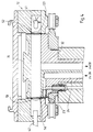
- the containers 4 are held by holders 21, such as grippers or the like, on the circumference of the circular conveyor 11 in the receptacles 14.
- a gas extraction device 22 is located above the bottles or the receptacles 14. This has a compressed air line 23 leading into a cylinder 24.
- the cylinder 24 is located coaxially above the container 4 held by the holder 21.
- a compressed air lance 26, which can be inserted with its lower end into the container 4, projects tightly into the cylinder 24 in the opening region of the container 24. It is held by a movable block 27, which can be moved up and down on the circumference of the circular conveyor 11, the upper end of the lance 26 being inserted more or less deeply into the cylinder 24 and thereby moving out of the containers 4 or into them is driven in.
- a gas sampling lance 28 which opens at its lower end into a cap 29 which is provided on its lower end face with an annular seal 31 which, when the block 27 moves downward, firmly and sealingly on the upper edge of the container 4 is attachable.
- the lance 28 also projects into a cylinder 32 which opens into the cuvette 16 from its upper side.
- the cuvette 16 is provided with two outlets 33 which can be connected to an outlet line 36 via a valve 34.
- the compressed air line 23 can be connected to a compressed air source (not shown).
- the block 27, which carries the lances 26, 28, moves downward from an upper position and thereby leads the lower end of the Lance 26 into the openings of the container 4 until the seal 31 of the cap 29 firmly on the edge of the opening of the container 4 rests.
- the compressed air line 23, the cylinder 24 and the lance 26 pressurized gas, which may also be compressed air, from the compressed gas source (not shown) into the bottle 24. It is essential that the gas itself does not have any absorption bands in the region in which absorption bands from foreign gases or gases caused by foreign substances are expected.
- the air in the bottle with the gaseous impurity components which were previously operated by the heating device 13 from the wall of the bottle into the interior, is removed from the container via the Lance 28 removed and driven into the cuvette 16.
- neutral purging gas located in the cuvette and, if appropriate, also initially the first portion of the measurement gas funneled on the bottle are displaced from the cuvette 16 through the outlets 33 until the valve 34 is closed.
- the detector device 12 may have a plurality of light sources 41 and detectors 42.
- the cuvette 16 is provided with viewing windows 43, 44 on its end faces.
- the detector device 12 can have a plurality of units which are provided for different gas fractions and their absorption bands. If the cuvette has been brought out of the detector device by further movement of the circular conveyor 11, it can be flushed through air or a neutral gas - via the inlet cylinder 32 and the outlets 33 - and also heated to assist in expelling the gas removed from the container can be.
- the district sponsors work intermittently.
- FIGS. 3 and 4 show sections of a further preferred embodiment of the device according to the invention, FIG. 3 showing a section in the area of rinsing outlets 33 and FIG. 4 showing a section in the area of a detector device 12.
- the end faces 51, 52 of the measuring cell 16 are not provided with viewing windows, but rather are designed to be open.
- the end faces 51, 52 of the measuring cuvette 16 are at least over the circumference of the circular conveyor in the area in which the cuvette contains measuring gas, but preferably also in the area that follows the flushing station with neutral gas, by largely closed inner and outer walls 53, 54 covered.
- the gap between the end faces 51, 52 of the cuvette 16 and the stationary walls 53, 54 is in the range of a few hundredths of a millimeter, for example between 20 and 50 micrometers. It has already been found that the loss of measurement gas in the cuvette 16 through this column is negligible.
- the cuvette 16 is located in the area of the rinsing station for the cuvette 16 with openings 33, 33a in the walls 53, 54 surrounding it inside and outside.
- the opening 33 is a purge gas outlet 33, while the opening 33a is either can also be such an outlet or a purge air inlet.
- the rinsing air can be supplied via the sampling lance 28 rotating with the cuvette and the feed cylinder 32, the rinsing air then being supplied to these in a suitable manner (via a stationary slot opening).
- the design of the device in the area of the sampling station is essentially the same, but the pressure line 23 running around the cuvette 16 is guided past a corresponding stationary feed inlet area.
- FIG. 4 shows a section in the area of the detector device.
- the detector device also has a light source 41 and a detector 42 (if necessary, a plurality of detector devices 12 for different foreign gas components can be arranged one behind the other).
- An optical system with lenses 56, 57 is also provided, through which the light coming from the light source 41 is parallelized through the cuvette 16 or focused on the detector 42.
Landscapes
- Health & Medical Sciences (AREA)
- Chemical & Material Sciences (AREA)
- Life Sciences & Earth Sciences (AREA)
- General Health & Medical Sciences (AREA)
- Physics & Mathematics (AREA)
- Analytical Chemistry (AREA)
- Biochemistry (AREA)
- Engineering & Computer Science (AREA)
- General Physics & Mathematics (AREA)
- Immunology (AREA)
- Pathology (AREA)
- Mechanical Engineering (AREA)
- Food Science & Technology (AREA)
- Medicinal Chemistry (AREA)
- Optical Measuring Cells (AREA)
- Investigating Or Analysing Materials By Optical Means (AREA)
Applications Claiming Priority (2)
| Application Number | Priority Date | Filing Date | Title |
|---|---|---|---|
| DE4126885 | 1991-08-14 | ||
| DE4126885A DE4126885A1 (de) | 1991-08-14 | 1991-08-14 | Verfahren und vorrichtung zum untersuchen von behaeltnissen auf fremdstoffe |
Publications (3)
| Publication Number | Publication Date |
|---|---|
| EP0534096A2 true EP0534096A2 (fr) | 1993-03-31 |
| EP0534096A3 EP0534096A3 (en) | 1994-08-24 |
| EP0534096B1 EP0534096B1 (fr) | 1997-11-05 |
Family
ID=6438293
Family Applications (1)
| Application Number | Title | Priority Date | Filing Date |
|---|---|---|---|
| EP92113169A Expired - Lifetime EP0534096B1 (fr) | 1991-08-14 | 1992-08-01 | Procédé et dispositif pour examiner des impuretés dans des récipients |
Country Status (2)
| Country | Link |
|---|---|
| EP (1) | EP0534096B1 (fr) |
| DE (2) | DE4126885A1 (fr) |
Cited By (7)
| Publication number | Priority date | Publication date | Assignee | Title |
|---|---|---|---|---|
| US5365771A (en) * | 1992-07-09 | 1994-11-22 | Elpatronic Ag | Process and apparatus for testing bottles for contamination |
| DE4427314A1 (de) * | 1994-08-02 | 1996-02-15 | Graessle Walter Gmbh | Vorrichtung zur Untersuchung von Behältern auf Fremdgase |
| TR28242A (tr) * | 1992-06-01 | 1996-03-28 | Coca Cola Co | Kaplarin icinde maddelerin mevcut oldugunu örnekleme ve tayin etme icin bir usul ve sistem. |
| EP0672900A3 (fr) * | 1994-03-17 | 1996-06-05 | Elpatronic Ag | Méthode de nettoyage d'un système de contrÔle de bouteilles. |
| US5703300A (en) * | 1995-06-08 | 1997-12-30 | Elpatronic Ag | Container inspection apparatus |
| DE102004034852A1 (de) * | 2004-07-19 | 2006-02-16 | Krieg, Gunther, Prof. Dipl.-Phys. Dr.-Ing. | Verfahren und Vorrichtung zum Untersuchen von Behältern auf Fremdstoffe |
| JP2010509142A (ja) * | 2006-11-13 | 2010-03-25 | カーハーエス・アクチエンゲゼルシヤフト | 瓶またはそのような容器を検査するための方法、ならびに瓶またはそのような容器の検査区間または点検区間のための測定設備 |
Families Citing this family (5)
| Publication number | Priority date | Publication date | Assignee | Title |
|---|---|---|---|---|
| DE10200349A1 (de) * | 2002-01-08 | 2003-07-17 | Gerhart Schroff | Verfahren und Anordnung zur Fremdgaserkennung im Strahlengang optischer Abbildungs- und/oder Strahlführungssysteme |
| DE202004008202U1 (de) * | 2004-05-18 | 2005-09-29 | Krones Ag | Vorrichtung zum Entnehmen von Gasproben aus Hohlgefäßen |
| DE202004020280U1 (de) * | 2004-12-30 | 2006-02-09 | Krones Ag | Vorrichtung zum Entnehmen von Gasproben aus Hohlgefäßen |
| DE102007062812A1 (de) * | 2007-12-21 | 2009-07-16 | Khs Ag | Vorrichtung zum Behandeln von Flaschen oder dergleichen Behälter, insbesondere Füllmaschine |
| DE102011083037A1 (de) | 2011-09-20 | 2013-03-21 | Krones Aktiengesellschaft | Verfahren und Vorrichtung zur Inspektion von Behältern und Vorformlingen |
Family Cites Families (12)
| Publication number | Priority date | Publication date | Assignee | Title |
|---|---|---|---|---|
| US3266292A (en) * | 1964-06-08 | 1966-08-16 | Nat Distillers Chem Corp | Method for detecting volatile organic contaminants in reusable containers |
| US3321954A (en) * | 1966-07-20 | 1967-05-30 | Nat Distillers Chem Corp | Contaminant detection apparatus |
| DE7531561U (de) * | 1975-10-04 | 1976-02-19 | Kronseder, Hermann, 8404 Woerth | Vorrichtung zum pruefen von transparenten getraenkeflaschen auf sauberkeit |
| DE3023211A1 (de) * | 1979-06-28 | 1981-01-22 | Ti Fords Ltd | Verfahren und vorrichtung zur ermittlung einer waesserigen fluessigkeit in flaschen und behaeltern |
| JPS6041850U (ja) * | 1983-08-30 | 1985-03-25 | 株式会社 堀場製作所 | ガス分析計 |
| DE3534756A1 (de) * | 1985-09-28 | 1987-04-02 | Seitz Enzinger Noll Masch | Verfahren zur erkennung von verunreinigten kegs und anlage zur durchfuehrung des verfahrens |
| US4791820A (en) * | 1987-07-31 | 1988-12-20 | Pharmacology & Toxicology Research Laboratory | Apparatus module for collection of volatiles from test sample |
| US4880120A (en) * | 1987-09-02 | 1989-11-14 | The Coca-Cola Company | Plastic container inspection process |
| DE3908934A1 (de) * | 1989-03-18 | 1990-09-20 | Msi Elektronik Gmbh | Vorrichtung zur gasanalyse |
| DE9002150U1 (de) * | 1990-02-23 | 1990-04-26 | Umweltschutz-Gasmeßtechnik Teichert GmbH, 8500 Nürnberg | Gerät zur Messung der Zusammensetzung von Gasen und Luft |
| DE4042557C2 (de) * | 1990-12-06 | 1996-11-28 | Lehmann Martin | Verfahren zur Analyse von Gasproben und Analyseanordnung |
| DE9114357U1 (de) * | 1991-11-18 | 1992-03-26 | Holstein Und Kappert Ag, 4600 Dortmund | Vorrichtung zur Fremdstoffinspektion von wiederverwendbaren Gefäßen |
-
1991
- 1991-08-14 DE DE4126885A patent/DE4126885A1/de not_active Withdrawn
-
1992
- 1992-08-01 DE DE59209009T patent/DE59209009D1/de not_active Expired - Lifetime
- 1992-08-01 EP EP92113169A patent/EP0534096B1/fr not_active Expired - Lifetime
Cited By (11)
| Publication number | Priority date | Publication date | Assignee | Title |
|---|---|---|---|---|
| TR28242A (tr) * | 1992-06-01 | 1996-03-28 | Coca Cola Co | Kaplarin icinde maddelerin mevcut oldugunu örnekleme ve tayin etme icin bir usul ve sistem. |
| EP0643840A4 (fr) * | 1992-06-01 | 1996-05-01 | Coca Cola Co | Methode et systeme d'echantillonnage et de determination de la presence de certains composes dans des recipients. |
| US5365771A (en) * | 1992-07-09 | 1994-11-22 | Elpatronic Ag | Process and apparatus for testing bottles for contamination |
| EP0672900A3 (fr) * | 1994-03-17 | 1996-06-05 | Elpatronic Ag | Méthode de nettoyage d'un système de contrÔle de bouteilles. |
| US5613713A (en) * | 1994-03-17 | 1997-03-25 | Elpatronic Ag | Arrangement for cleaning a container testing apparatus |
| EP0810040A1 (fr) * | 1994-03-17 | 1997-12-03 | Elpatronic Ag | Appareil de nettoyage d'un système de contrÔle de récipients |
| DE4427314A1 (de) * | 1994-08-02 | 1996-02-15 | Graessle Walter Gmbh | Vorrichtung zur Untersuchung von Behältern auf Fremdgase |
| US5703300A (en) * | 1995-06-08 | 1997-12-30 | Elpatronic Ag | Container inspection apparatus |
| DE102004034852A1 (de) * | 2004-07-19 | 2006-02-16 | Krieg, Gunther, Prof. Dipl.-Phys. Dr.-Ing. | Verfahren und Vorrichtung zum Untersuchen von Behältern auf Fremdstoffe |
| DE102004034852B4 (de) * | 2004-07-19 | 2015-06-18 | Gunther Krieg | Verfahren und Vorrichtung zum Untersuchen von Behältern auf Fremdstoffe |
| JP2010509142A (ja) * | 2006-11-13 | 2010-03-25 | カーハーエス・アクチエンゲゼルシヤフト | 瓶またはそのような容器を検査するための方法、ならびに瓶またはそのような容器の検査区間または点検区間のための測定設備 |
Also Published As
| Publication number | Publication date |
|---|---|
| DE4126885A1 (de) | 1993-02-18 |
| EP0534096B1 (fr) | 1997-11-05 |
| EP0534096A3 (en) | 1994-08-24 |
| DE59209009D1 (de) | 1997-12-11 |
Similar Documents
| Publication | Publication Date | Title |
|---|---|---|
| EP0579952B1 (fr) | Procédé et dispositif pour contrôler l'état de propieté de bouteilles | |
| EP1811289B1 (fr) | Procédé et appareil d'inspection de bouteilles et récipents similaires | |
| EP0534096B1 (fr) | Procédé et dispositif pour examiner des impuretés dans des récipients | |
| DE19727942C2 (de) | Maschine und Verfahren zum Verschließen von Flaschen mit Verschlußkappen | |
| EP2092291A1 (fr) | Procédé d'inspection de bouteilles ou récipients analogues et poste de mesure pour un parcours d'inspection ou de contrôle de bouteilles ou récipients analogues | |
| EP3853168B1 (fr) | Installation et procédé de traitement de boissons pour le remplissage d'une boisson dans des conteneurs | |
| DE2440805B2 (de) | Verfahren und vorrichtung zum analysieren einer reihe von fluidproben | |
| EP2450696A1 (fr) | Dispositif et procédé destinés à l'inspection de récipients | |
| EP3578158A1 (fr) | Machine de remplissage de capsules avec unité de nettoyage et détecteur de corps étranger | |
| DE60304764T2 (de) | Greifmittel zur Handhabung von Blutplasmabehältern | |
| DE3028818C2 (fr) | ||
| EP3684696B1 (fr) | Dispositif de fabrication et de remplissage de recipients | |
| DE9314182U1 (de) | Vorrichtung zur massenspektrometrischen Prüfung von Flaschen auf Verunreinigungen | |
| DE69002211T2 (de) | Vorrichtung zum Sammeln des Seitenstromes von Zigarettenrauch. | |
| DE4427314C2 (de) | Vorrichtung zur Untersuchung von Behältern auf Fremdgase | |
| EP0653964B1 (fr) | Procede et dispositif pour l'inspection de recipients transportes par un convoyeur | |
| EP0747690A1 (fr) | Dispositif de contrÔle des récipients | |
| DE2613310C2 (de) | Verfahren und Vorrichtung zum Einspeisen fester Produkte in einen Reaktionsbehälter | |
| DE2913541A1 (de) | Vorrichtung zur optischen pruefung und kontrolle von flaschen und ampullen | |
| DE2813757C2 (de) | Vorrichtung zum Sortieren von Gegenständen nach dem Material | |
| EP0778064A2 (fr) | Dispositif filtrant et procédé de filtration | |
| DE3108912A1 (de) | Verfahren zur entfernung loser partikel aus bechern und vorrichtung zur durchfuehrung des verfahrens | |
| DE3311360C2 (fr) | ||
| DE1773434A1 (de) | Verfahren und Einrichtung zur Behandlung von Proben zur Verwendung bei Untersuchungen mit radioaktiven Isotopen | |
| EP3418709A2 (fr) | Procede et dispositif de detection de fuite dans des recipients sous pression |
Legal Events
| Date | Code | Title | Description |
|---|---|---|---|
| PUAI | Public reference made under article 153(3) epc to a published international application that has entered the european phase |
Free format text: ORIGINAL CODE: 0009012 |
|
| AK | Designated contracting states |
Kind code of ref document: A2 Designated state(s): BE CH DE FR IT LI SE |
|
| PUAL | Search report despatched |
Free format text: ORIGINAL CODE: 0009013 |
|
| AK | Designated contracting states |
Kind code of ref document: A3 Designated state(s): BE CH DE FR IT LI SE |
|
| 17P | Request for examination filed |
Effective date: 19950211 |
|
| 17Q | First examination report despatched |
Effective date: 19960522 |
|
| GRAG | Despatch of communication of intention to grant |
Free format text: ORIGINAL CODE: EPIDOS AGRA |
|
| GRAH | Despatch of communication of intention to grant a patent |
Free format text: ORIGINAL CODE: EPIDOS IGRA |
|
| GRAH | Despatch of communication of intention to grant a patent |
Free format text: ORIGINAL CODE: EPIDOS IGRA |
|
| GRAA | (expected) grant |
Free format text: ORIGINAL CODE: 0009210 |
|
| AK | Designated contracting states |
Kind code of ref document: B1 Designated state(s): BE CH DE FR IT LI SE |
|
| RAP2 | Party data changed (patent owner data changed or rights of a patent transferred) |
Owner name: KHS MASCHINEN- UND ANLAGENBAU AKTIENGESELLSCHAFT |
|
| RIN2 | Information on inventor provided after grant (corrected) |
Free format text: RUPP, MICHAEL |
|
| REG | Reference to a national code |
Ref country code: CH Ref legal event code: EP |
|
| REF | Corresponds to: |
Ref document number: 59209009 Country of ref document: DE Date of ref document: 19971211 |
|
| ITF | It: translation for a ep patent filed | ||
| PG25 | Lapsed in a contracting state [announced via postgrant information from national office to epo] |
Ref country code: SE Free format text: LAPSE BECAUSE OF FAILURE TO SUBMIT A TRANSLATION OF THE DESCRIPTION OR TO PAY THE FEE WITHIN THE PRESCRIBED TIME-LIMIT Effective date: 19980205 |
|
| ET | Fr: translation filed | ||
| PG25 | Lapsed in a contracting state [announced via postgrant information from national office to epo] |
Ref country code: BE Free format text: LAPSE BECAUSE OF NON-PAYMENT OF DUE FEES Effective date: 19980831 |
|
| PLBE | No opposition filed within time limit |
Free format text: ORIGINAL CODE: 0009261 |
|
| STAA | Information on the status of an ep patent application or granted ep patent |
Free format text: STATUS: NO OPPOSITION FILED WITHIN TIME LIMIT |
|
| 26N | No opposition filed | ||
| BERE | Be: lapsed |
Owner name: RUPP MICHAEL Effective date: 19980831 |
|
| PGFP | Annual fee paid to national office [announced via postgrant information from national office to epo] |
Ref country code: CH Payment date: 20020529 Year of fee payment: 11 |
|
| PGFP | Annual fee paid to national office [announced via postgrant information from national office to epo] |
Ref country code: FR Payment date: 20020614 Year of fee payment: 11 |
|
| PG25 | Lapsed in a contracting state [announced via postgrant information from national office to epo] |
Ref country code: CH Free format text: LAPSE BECAUSE OF NON-PAYMENT OF DUE FEES Effective date: 20030831 Ref country code: LI Free format text: LAPSE BECAUSE OF NON-PAYMENT OF DUE FEES Effective date: 20030831 |
|
| REG | Reference to a national code |
Ref country code: CH Ref legal event code: PL |
|
| PG25 | Lapsed in a contracting state [announced via postgrant information from national office to epo] |
Ref country code: FR Free format text: LAPSE BECAUSE OF NON-PAYMENT OF DUE FEES Effective date: 20040430 |
|
| REG | Reference to a national code |
Ref country code: FR Ref legal event code: ST |
|
| PGFP | Annual fee paid to national office [announced via postgrant information from national office to epo] |
Ref country code: DE Payment date: 20110823 Year of fee payment: 20 |
|
| PGFP | Annual fee paid to national office [announced via postgrant information from national office to epo] |
Ref country code: IT Payment date: 20110824 Year of fee payment: 20 |
|
| REG | Reference to a national code |
Ref country code: DE Ref legal event code: R071 Ref document number: 59209009 Country of ref document: DE |
|
| REG | Reference to a national code |
Ref country code: DE Ref legal event code: R071 Ref document number: 59209009 Country of ref document: DE |
|
| PG25 | Lapsed in a contracting state [announced via postgrant information from national office to epo] |
Ref country code: DE Free format text: LAPSE BECAUSE OF EXPIRATION OF PROTECTION Effective date: 20120802 |