EP0534332A1 - Hydraulische Servoeinheit, insbesondere für den Lenkmechanismus eines Kraftfahrzeuges - Google Patents
Hydraulische Servoeinheit, insbesondere für den Lenkmechanismus eines Kraftfahrzeuges Download PDFInfo
- Publication number
- EP0534332A1 EP0534332A1 EP92116047A EP92116047A EP0534332A1 EP 0534332 A1 EP0534332 A1 EP 0534332A1 EP 92116047 A EP92116047 A EP 92116047A EP 92116047 A EP92116047 A EP 92116047A EP 0534332 A1 EP0534332 A1 EP 0534332A1
- Authority
- EP
- European Patent Office
- Prior art keywords
- servo unit
- vehicle
- steering
- steering wheel
- movement
- Prior art date
- Legal status (The legal status is an assumption and is not a legal conclusion. Google has not performed a legal analysis and makes no representation as to the accuracy of the status listed.)
- Granted
Links
Images
Classifications
-
- B—PERFORMING OPERATIONS; TRANSPORTING
- B62—LAND VEHICLES FOR TRAVELLING OTHERWISE THAN ON RAILS
- B62D—MOTOR VEHICLES; TRAILERS
- B62D6/00—Arrangements for automatically controlling steering depending on driving conditions sensed and responded to, e.g. control circuits
-
- B—PERFORMING OPERATIONS; TRANSPORTING
- B62—LAND VEHICLES FOR TRAVELLING OTHERWISE THAN ON RAILS
- B62D—MOTOR VEHICLES; TRAILERS
- B62D5/00—Power-assisted or power-driven steering
- B62D5/06—Power-assisted or power-driven steering fluid, i.e. using a pressurised fluid for most or all the force required for steering a vehicle
- B62D5/065—Power-assisted or power-driven steering fluid, i.e. using a pressurised fluid for most or all the force required for steering a vehicle characterised by specially adapted means for varying pressurised fluid supply based on need, e.g. on-demand, variable assist
Definitions
- the invention relates to a hydraulic servo unit, primarily for the steering mechanism of a vehicle, according to the precharacterising part of claim 1.
- hydraulic servo units of said kind are designed such that a change in the position of the operating member results in a proportional change of an executive device.
- the operating member in question may be the steering wheel of a vehicle, a lever, a shuttle, and the like, and the executive device may be a steering cylinder.
- Such a control normally comprises a servo system in which pressure oil is passed via a hose system and a steering unit to a steering cylinder which brings about a turn of the guide wheels corresponding to the turn of the steering wheel.
- the relationship between the turn of the steering wheel and the turn of the guide wheels is determined by the dimensioning of the steering unit, the length of stroke of the steering cylinder, etc.
- the steering wheel from an initial position with the guide wheels parallel to the longitudinal axis of the vehicle, may need to be turned +/- two turns for the guide wheels to be turned from the maximum position in one direction to the maximum position in the other direction.
- the battery of the vehicle drives in an uncontrolled manner an electric motor connected to a hydraulic pump.
- a steering unit mounted on the steering column is influenced in such a way that an internal circular slide shuts off the free circulation of the pressure oil and conducts the in-flowing oil to one of the sides of a measuring pump. Since the quantity of oil fed forward by the measuring pump is constant, its rotor when rotating transports a carefully measured oil quantity to the steering cylinder.
- the rotor of the measuring pump is fixed to an external circular slide of the steering unit, which means that when the rotor rotates also the external circular slide will rotate.
- the circular slide will shut off the oil flow to the measuring pump. In this way the quantity of fluid corresponding to the turn of the steering wheel is very accurately determined.
- the return oil coming from the steering cylinder is guided back to the oil tank by the circular slide via its own channels.
- a control and servo system as described above means that the turning rate of the guide wheels is always the same independently of the extent of the deflection and the velocity of movement of the steering wheel.
- the turning rate of the guide wheels is determined by the dimensioning of the parts included. Because the hydraulic pump always runs at a more or less constant speed, this prior design also entails considerable power losses and drainage of the capacity of the battery, resulting in reduced time between chargings, overhauls, etc.
- the invention aims at providing a hydraulic servo unit of the above-mentioned kind, which is capable of operating with an unambiguous, for example proportional, relationship between the velocity of the rotational or linear movement of said operating member of the servo unit and the rate of flow of the servo unit.
- the turning of the guide wheels occur at a turning rate which corresponds to the turning rate of the steering wheel or the rate of change of a lever.
- a condition for this is that the turning rate of the steering wheel or the liner moving rate of the lever is known.
- the invention need not necessarily be associated with the movement of a steering wheel or a lever.
- the principle can always be applied where there is a need for a clear relationship between the velocity of movement of a member and a flow rate proportional to that velocity of movement.
- the invention is used for a vehicle, the latter need not, of course, be electrically driven.
- the hydraulic pump could be stationary in case of a constant deflection of the steering wheel.
- the speed control also in case of a constant deflection of the steering wheel, is given a certain speed reference value corresponding to a minimum no-load speed.
- the invention entails a considerable energy saving since the hydraulic pump at a constant steering wheel deflection will only run at the no-load speed. This also entails for an electric vehicle a longer running time between battery chargings and a shorter charging time.
- a manner of driving according to the invention also means that the wear on movable and rotating parts is considerably reduced.
- the controlled speed also means that the flow at a certain turning rate will always be the same independent of load and battery voltage.
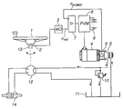
- the servo unit is used for steering a vehicle according to the accompanying drawing:
- the sensor may, for example, be an inductive sensor which generates a pulse train with a frequency corresponding to the turning rate.
- the measured value obtained is converted in a convertor 3 into a suitable reference value signal n ref for a hydraulic pump 5 which is driven by a speed-controlled motor 4.
- the speed control otherwise comprises a measuring means 6 for supplying the actual value n actual of the motor.
- the reference and actual values are supplied to a speed regulator 7 which controls the executive device 8 feeding the motor.
- the energy source for driving the motor is suitably the electric battery 9 of the vehicle.
- How the control is performed by means of the executive device is, per se, irrelevant and can occur in many different ways.
- One appropriate method is the use of a pulse-width modulated transistorized control device PVM.
- a simplified flow chart for the hydraulic system is also shown in the figure.
- a constant steering wheel deflection that is, when the rate of change is zero
- the motor runs at minimum no-load speed corresponding to an n refmin which, for example, can be generated by the measured value convertor 3 to be ready when the steering wheel is to be turned.
- the oil which is thereby fed forward is conducted via a pressure relief valve 10 back to an oil tank 11.
- a speed reference value for the pump motor 4 is obtained from the speed sensor 2.
- the hydraulic pump 5 via the oil tank and a steering unit 12 on the steering column 13, supplies the steering cylinder 14 with the necessary pressure oil for movement of the piston of the steering cylinder to an extent necessary for the turning of the guide wheels to correspond to the turning of the steering wheel.
- a certain quantity of oil will flow into one side of the piston and a corresponding quantity of oil will be discharged from the other side of the piston and be led back, via the steering unit, to the oil tank 11.
Landscapes
- Engineering & Computer Science (AREA)
- Chemical & Material Sciences (AREA)
- Combustion & Propulsion (AREA)
- Transportation (AREA)
- Mechanical Engineering (AREA)
- Steering Control In Accordance With Driving Conditions (AREA)
- Power Steering Mechanism (AREA)
- Electrical Discharge Machining, Electrochemical Machining, And Combined Machining (AREA)
- Control Of Eletrric Generators (AREA)
Applications Claiming Priority (2)
| Application Number | Priority Date | Filing Date | Title |
|---|---|---|---|
| SE9102795A SE504084C2 (sv) | 1991-09-26 | 1991-09-26 | Servoaggregat för fordon |
| SE9102795 | 1991-09-26 |
Publications (2)
| Publication Number | Publication Date |
|---|---|
| EP0534332A1 true EP0534332A1 (de) | 1993-03-31 |
| EP0534332B1 EP0534332B1 (de) | 2000-03-08 |
Family
ID=20383837
Family Applications (1)
| Application Number | Title | Priority Date | Filing Date |
|---|---|---|---|
| EP92116047A Expired - Lifetime EP0534332B1 (de) | 1991-09-26 | 1992-09-19 | Hydraulische Servoeinheit, insbesondere für den Lenkmechanismus eines Kraftfahrzeuges |
Country Status (5)
| Country | Link |
|---|---|
| EP (1) | EP0534332B1 (de) |
| DE (1) | DE69230743T2 (de) |
| FI (1) | FI100650B (de) |
| NO (1) | NO302806B1 (de) |
| SE (1) | SE504084C2 (de) |
Cited By (10)
| Publication number | Priority date | Publication date | Assignee | Title |
|---|---|---|---|---|
| EP0607888A1 (de) * | 1993-01-21 | 1994-07-27 | Still Gmbh | Hydraulische Lenkregelung bei einem Elektrofahrzeug |
| AU664519B2 (en) * | 1993-09-03 | 1995-11-16 | Kubota Corporation | Hydraulic control system |
| DE19516498C1 (de) * | 1995-05-05 | 1996-08-29 | Trw Fahrwerksyst Gmbh & Co | Verfahren zur Regelung der Pumpendrehzahl einer hydraulischen Servolenkeinrichtung |
| EP0791523A3 (de) * | 1996-02-20 | 1997-11-12 | Koyo Seiko Co., Ltd. | Servolenkung |
| EP0770539A3 (de) * | 1995-10-25 | 1998-03-18 | Koyo Seiko Co., Ltd. | Servolenkung |
| EP0926042A1 (de) * | 1997-12-16 | 1999-06-30 | Kabushiki Kaisha Toyoda Jidoshokki Seisakusho | Hydraulische Lenkeinrichtung für Gabelhubwagen |
| DE19919393A1 (de) * | 1999-04-28 | 2000-11-02 | Steinbock Boss Gmbh Foerdertec | Hilfskraft-Lenksystem für ein Fahrzeug, insbesondere einen Hubstapler |
| FR2796029A1 (fr) * | 1999-07-07 | 2001-01-12 | Toyoda Automatic Loom Works | Systeme de direction assistee |
| DE4420309B4 (de) * | 1994-06-10 | 2008-03-27 | Siemens Ag | Verfahren und Anordnung zur Ansteuerung einer elektrohydraulischen Druckversorgung für eine Hilfskrafteinrichtung eines Kraftfahrzeuges |
| CN106828595A (zh) * | 2017-02-10 | 2017-06-13 | 宁夏百辰工业产品设计有限公司 | 转向机怠速操作液压调整流量筛选组件 |
Families Citing this family (1)
| Publication number | Priority date | Publication date | Assignee | Title |
|---|---|---|---|---|
| JP4062085B2 (ja) † | 2002-12-18 | 2008-03-19 | 株式会社豊田自動織機 | 電気式産業車両の操舵装置 |
Citations (5)
| Publication number | Priority date | Publication date | Assignee | Title |
|---|---|---|---|---|
| US3756337A (en) * | 1972-04-05 | 1973-09-04 | Allis Chalmers | Power steering and control therefor |
| US3991846A (en) * | 1975-08-07 | 1976-11-16 | Clark Equipment Company | Power steering system |
| FR2454397A1 (fr) * | 1979-04-19 | 1980-11-14 | Still Gmbh | Dispositif de direction pour vehicule a direction hydraulique assistee |
| EP0044733A1 (de) * | 1980-07-18 | 1982-01-27 | Nissan Motor Co., Ltd. | Hydraulisches Hilfskraft-Fahrzeuglenksystem mit Steuereinrichtung zur Betätigung der Hilfskraftpumpe |
| EP0053429A2 (de) * | 1980-11-03 | 1982-06-09 | Clark Equipment Company | Servolenkungseinrichtung |
-
1991
- 1991-09-26 SE SE9102795A patent/SE504084C2/sv not_active IP Right Cessation
-
1992
- 1992-09-19 EP EP92116047A patent/EP0534332B1/de not_active Expired - Lifetime
- 1992-09-19 DE DE69230743T patent/DE69230743T2/de not_active Expired - Lifetime
- 1992-09-25 NO NO923742A patent/NO302806B1/no not_active IP Right Cessation
- 1992-09-25 FI FI924315A patent/FI100650B/fi not_active IP Right Cessation
Patent Citations (5)
| Publication number | Priority date | Publication date | Assignee | Title |
|---|---|---|---|---|
| US3756337A (en) * | 1972-04-05 | 1973-09-04 | Allis Chalmers | Power steering and control therefor |
| US3991846A (en) * | 1975-08-07 | 1976-11-16 | Clark Equipment Company | Power steering system |
| FR2454397A1 (fr) * | 1979-04-19 | 1980-11-14 | Still Gmbh | Dispositif de direction pour vehicule a direction hydraulique assistee |
| EP0044733A1 (de) * | 1980-07-18 | 1982-01-27 | Nissan Motor Co., Ltd. | Hydraulisches Hilfskraft-Fahrzeuglenksystem mit Steuereinrichtung zur Betätigung der Hilfskraftpumpe |
| EP0053429A2 (de) * | 1980-11-03 | 1982-06-09 | Clark Equipment Company | Servolenkungseinrichtung |
Non-Patent Citations (2)
| Title |
|---|
| PATENT ABSTRACTS OF JAPAN vol. 11, no. 235 (M-612)31 July 1987 & JP-A-62 046 766 ( MAZDA MOTORS ) 28 February 1987 * |
| PATENT ABSTRACTS OF JAPAN vol. 12, no. 392 (M-755)19 October 1988 & JP-A-63 141 878 ( JIDOSHA KIKI ) 14 June 1988 * |
Cited By (16)
| Publication number | Priority date | Publication date | Assignee | Title |
|---|---|---|---|---|
| EP0607888A1 (de) * | 1993-01-21 | 1994-07-27 | Still Gmbh | Hydraulische Lenkregelung bei einem Elektrofahrzeug |
| AU664519B2 (en) * | 1993-09-03 | 1995-11-16 | Kubota Corporation | Hydraulic control system |
| US5513551A (en) * | 1993-09-03 | 1996-05-07 | Kubota Corporation | Hydraulic control system |
| DE4420309B4 (de) * | 1994-06-10 | 2008-03-27 | Siemens Ag | Verfahren und Anordnung zur Ansteuerung einer elektrohydraulischen Druckversorgung für eine Hilfskrafteinrichtung eines Kraftfahrzeuges |
| DE19516498C1 (de) * | 1995-05-05 | 1996-08-29 | Trw Fahrwerksyst Gmbh & Co | Verfahren zur Regelung der Pumpendrehzahl einer hydraulischen Servolenkeinrichtung |
| EP0741068A3 (de) * | 1995-05-05 | 1997-11-12 | TRW Fahrwerksysteme GmbH & Co. KG | Verfahren zur Regelung der Pumpendrehzahl einer hydraulischen Servolenkeinrichtung |
| US5816360A (en) * | 1995-05-05 | 1998-10-06 | Trw Fahrwerksysteme Gmbh & Co. Kg | Method for controlling the pump speed of a hydraulic power steering device |
| EP0770539A3 (de) * | 1995-10-25 | 1998-03-18 | Koyo Seiko Co., Ltd. | Servolenkung |
| US5954152A (en) * | 1995-10-25 | 1999-09-21 | Koyo Seiko Co., Ltd. | Power steering device |
| EP0791523A3 (de) * | 1996-02-20 | 1997-11-12 | Koyo Seiko Co., Ltd. | Servolenkung |
| US5936379A (en) * | 1996-02-20 | 1999-08-10 | Koyo Seiko Co., Ltd. | Power steering apparatus having compensation for delay of oil pressure build-up |
| EP0926042A1 (de) * | 1997-12-16 | 1999-06-30 | Kabushiki Kaisha Toyoda Jidoshokki Seisakusho | Hydraulische Lenkeinrichtung für Gabelhubwagen |
| US6202410B1 (en) | 1997-12-16 | 2001-03-20 | Kabushiki Kaisha Toyoda Jidoshokki Seisakusho | Hydraulic system for forklift |
| DE19919393A1 (de) * | 1999-04-28 | 2000-11-02 | Steinbock Boss Gmbh Foerdertec | Hilfskraft-Lenksystem für ein Fahrzeug, insbesondere einen Hubstapler |
| FR2796029A1 (fr) * | 1999-07-07 | 2001-01-12 | Toyoda Automatic Loom Works | Systeme de direction assistee |
| CN106828595A (zh) * | 2017-02-10 | 2017-06-13 | 宁夏百辰工业产品设计有限公司 | 转向机怠速操作液压调整流量筛选组件 |
Also Published As
| Publication number | Publication date |
|---|---|
| SE504084C2 (sv) | 1996-11-04 |
| FI924315L (fi) | 1993-03-27 |
| SE9102795L (sv) | 1993-03-27 |
| DE69230743T2 (de) | 2000-10-26 |
| DE69230743D1 (de) | 2000-04-13 |
| EP0534332B1 (de) | 2000-03-08 |
| FI100650B (fi) | 1998-01-30 |
| SE9102795D0 (sv) | 1991-09-26 |
| FI924315A0 (fi) | 1992-09-25 |
| NO923742D0 (no) | 1992-09-25 |
| NO302806B1 (no) | 1998-04-27 |
| NO923742L (no) | 1993-03-29 |
Similar Documents
| Publication | Publication Date | Title |
|---|---|---|
| US4392540A (en) | Power steering device for a vehicle | |
| CA1059919A (en) | Power steering system | |
| US8596055B2 (en) | Hydraulic drive system | |
| US4457390A (en) | Power steering device | |
| EP0534332B1 (de) | Hydraulische Servoeinheit, insbesondere für den Lenkmechanismus eines Kraftfahrzeuges | |
| KR890000443B1 (ko) | 전동유압 동력핸들 조종장치 | |
| US4819429A (en) | Hydraulical drive system | |
| US20080277187A1 (en) | Power steering apparatus | |
| GB1424937A (en) | Automotive steering system process for the production of bis-halogen carbonyl anilines | |
| KR20010022460A (ko) | 닫힌 중앙 유압 파워스티어링 시스템 | |
| US4409789A (en) | Power steering system | |
| GB2332182A (en) | Method for controlling steering in a hydrostatic drive system having differential steer | |
| US4718514A (en) | Steering force control device for power steering apparatus | |
| US5857532A (en) | Differential steer system for a machine | |
| JP2004522909A (ja) | 特にかじ取り装置のための、油圧ポンプを備えたポンプシステム | |
| US4557343A (en) | Power steering control apparatus and method | |
| US8781683B2 (en) | Power steering apparatus and method | |
| US20190270480A1 (en) | Apparatus and method for turning steerable vehicle wheels | |
| RU2029891C1 (ru) | Электрогидравлический следящий привод | |
| KR200223589Y1 (ko) | 동력 조향장치 | |
| GB2087050A (en) | Hydrostatic Transmission Control System | |
| SU1138573A1 (ru) | Силова установка транспортного средства | |
| KR0151462B1 (ko) | 차속 감응형 동력 조향장치 | |
| KR100268087B1 (ko) | 속도감응형 파워스티어링 시스템 및 그 제어방법 | |
| KR0159744B1 (ko) | 파워스티어링 보조용 캠식 스티어링칼럼 |
Legal Events
| Date | Code | Title | Description |
|---|---|---|---|
| PUAI | Public reference made under article 153(3) epc to a published international application that has entered the european phase |
Free format text: ORIGINAL CODE: 0009012 |
|
| AK | Designated contracting states |
Kind code of ref document: A1 Designated state(s): CH DE DK FR GB IT LI SE |
|
| 17P | Request for examination filed |
Effective date: 19930512 |
|
| 17Q | First examination report despatched |
Effective date: 19940601 |
|
| RAP1 | Party data changed (applicant data changed or rights of an application transferred) |
Owner name: KALMAR LAST MASKIN VERKSTAD AB |
|
| GRAG | Despatch of communication of intention to grant |
Free format text: ORIGINAL CODE: EPIDOS AGRA |
|
| GRAG | Despatch of communication of intention to grant |
Free format text: ORIGINAL CODE: EPIDOS AGRA |
|
| GRAH | Despatch of communication of intention to grant a patent |
Free format text: ORIGINAL CODE: EPIDOS IGRA |
|
| GRAH | Despatch of communication of intention to grant a patent |
Free format text: ORIGINAL CODE: EPIDOS IGRA |
|
| RAP1 | Party data changed (applicant data changed or rights of an application transferred) |
Owner name: KALMAR INDUSTRIES SVERIGE AB |
|
| GRAA | (expected) grant |
Free format text: ORIGINAL CODE: 0009210 |
|
| AK | Designated contracting states |
Kind code of ref document: B1 Designated state(s): CH DE DK FR GB IT LI SE |
|
| PG25 | Lapsed in a contracting state [announced via postgrant information from national office to epo] |
Ref country code: SE Free format text: THE PATENT HAS BEEN ANNULLED BY A DECISION OF A NATIONAL AUTHORITY Effective date: 20000308 Ref country code: CH Free format text: LAPSE BECAUSE OF NON-PAYMENT OF DUE FEES Effective date: 20000308 Ref country code: LI Free format text: LAPSE BECAUSE OF NON-PAYMENT OF DUE FEES Effective date: 20000308 |
|
| REG | Reference to a national code |
Ref country code: CH Ref legal event code: EP |
|
| REF | Corresponds to: |
Ref document number: 69230743 Country of ref document: DE Date of ref document: 20000413 |
|
| ITF | It: translation for a ep patent filed | ||
| PG25 | Lapsed in a contracting state [announced via postgrant information from national office to epo] |
Ref country code: DK Free format text: LAPSE BECAUSE OF FAILURE TO SUBMIT A TRANSLATION OF THE DESCRIPTION OR TO PAY THE FEE WITHIN THE PRESCRIBED TIME-LIMIT Effective date: 20000608 |
|
| ET | Fr: translation filed | ||
| REG | Reference to a national code |
Ref country code: CH Ref legal event code: PL |
|
| PG25 | Lapsed in a contracting state [announced via postgrant information from national office to epo] |
Ref country code: GB Free format text: LAPSE BECAUSE OF NON-PAYMENT OF DUE FEES Effective date: 20000919 |
|
| PLBE | No opposition filed within time limit |
Free format text: ORIGINAL CODE: 0009261 |
|
| 26N | No opposition filed | ||
| GBPC | Gb: european patent ceased through non-payment of renewal fee |
Effective date: 20000919 |
|
| PGFP | Annual fee paid to national office [announced via postgrant information from national office to epo] |
Ref country code: DE Payment date: 20100921 Year of fee payment: 19 |
|
| PGFP | Annual fee paid to national office [announced via postgrant information from national office to epo] |
Ref country code: FR Payment date: 20110923 Year of fee payment: 20 |
|
| PGFP | Annual fee paid to national office [announced via postgrant information from national office to epo] |
Ref country code: IT Payment date: 20110919 Year of fee payment: 20 |
|
| REG | Reference to a national code |
Ref country code: DE Ref legal event code: R071 Ref document number: 69230743 Country of ref document: DE |
|
| REG | Reference to a national code |
Ref country code: DE Ref legal event code: R071 Ref document number: 69230743 Country of ref document: DE |
|
| PG25 | Lapsed in a contracting state [announced via postgrant information from national office to epo] |
Ref country code: DE Free format text: LAPSE BECAUSE OF EXPIRATION OF PROTECTION Effective date: 20120920 |