EP0534338A2 - Dispositif de contrôle pour une machine de forage de tunnels - Google Patents
Dispositif de contrôle pour une machine de forage de tunnels Download PDFInfo
- Publication number
- EP0534338A2 EP0534338A2 EP92116084A EP92116084A EP0534338A2 EP 0534338 A2 EP0534338 A2 EP 0534338A2 EP 92116084 A EP92116084 A EP 92116084A EP 92116084 A EP92116084 A EP 92116084A EP 0534338 A2 EP0534338 A2 EP 0534338A2
- Authority
- EP
- European Patent Office
- Prior art keywords
- sensor unit
- control device
- tunnel
- control
- signals
- Prior art date
- Legal status (The legal status is an assumption and is not a legal conclusion. Google has not performed a legal analysis and makes no representation as to the accuracy of the status listed.)
- Granted
Links
Images



Classifications
-
- E—FIXED CONSTRUCTIONS
- E21—EARTH OR ROCK DRILLING; MINING
- E21B—EARTH OR ROCK DRILLING; OBTAINING OIL, GAS, WATER, SOLUBLE OR MELTABLE MATERIALS OR A SLURRY OF MINERALS FROM WELLS
- E21B47/00—Survey of boreholes or wells
- E21B47/02—Determining slope or direction
- E21B47/022—Determining slope or direction of the borehole, e.g. using geomagnetism
-
- E—FIXED CONSTRUCTIONS
- E21—EARTH OR ROCK DRILLING; MINING
- E21B—EARTH OR ROCK DRILLING; OBTAINING OIL, GAS, WATER, SOLUBLE OR MELTABLE MATERIALS OR A SLURRY OF MINERALS FROM WELLS
- E21B7/00—Special methods or apparatus for drilling
- E21B7/04—Directional drilling
- E21B7/06—Deflecting the direction of boreholes
-
- E—FIXED CONSTRUCTIONS
- E21—EARTH OR ROCK DRILLING; MINING
- E21B—EARTH OR ROCK DRILLING; OBTAINING OIL, GAS, WATER, SOLUBLE OR MELTABLE MATERIALS OR A SLURRY OF MINERALS FROM WELLS
- E21B7/00—Special methods or apparatus for drilling
- E21B7/20—Driving or forcing casings or pipes into boreholes, e.g. sinking; Simultaneously drilling and casing boreholes
- E21B7/201—Driving or forcing casings or pipes into boreholes, e.g. sinking; Simultaneously drilling and casing boreholes with helical conveying means
Definitions
- the laser beam acts on eccentrically arranged photodiodes on the target.
- control signals are generated which act on the control unit of the jacking head and thereby return the jacking to the alignment with the target axis.
- a laser beam that is to say a light beam for controlling the advance
- a number of disadvantages which are caused by the properties of the laser beam and have a negative influence on the implementation of the control. This includes that uneven heating of the air in the tunnel tube can cause air stratifications that break the laser beam and thus cause an arcuate deviation from the target axis. Due to air turbulence in the tunnel tube, the laser beam can also be deformed to such an extent that that control is made impossible. If obstacles push the tunneling path out of the prescribed tunnel so much that the laser beam no longer strikes the target plate, tunneling control is also made impossible. Finally, a fundamental disadvantage of laser beam control is that, due to the linear propagation of the laser beam, a curved tunneling path cannot be traversed.
- US-A-4 282 470 also shows an electrically bound gyroscope with a digital captive circuit.
- DE-C-29 22 415 shows a navigation device for land, air or sea vehicles.
- the navigation device contains an inertial sensor unit with a two-axis, electrically bound gyroscope and two accelerometers. Location parameters are obtained from the signals of the sensor unit. The position is calculated from the position parameters and speed information from a speed sensor.
- this object is achieved in that an autonomous inertial sensor unit, which responds to changes in position in space, is connected as a control signal generator to the propulsion head or its carrier.
- the inertial sensor unit can be constructed with gyroscopes and accelerometers. However, the sensors of the inertial sensor unit can also contain rotational speed sensors that are based on the Sagnac effect, e.g. "Laser gyroscope”.
- control signals are supplied by an autonomous inertial sensor unit which is connected to the propulsion head.
- the sensor unit is independent of a laser beam or the visibility of a CCD camera. However, the sensor unit continuously delivers control signals.
- the sensor unit can expediently be coupled to the propulsion head in a defined position by releasable connecting means and can optionally be returned to a precisely measured starting position for drift correction.
- This starting position can be measured using a meridian gyro.
- the sensor unit is used for a working according to the shield construction
- the tunnel boring machine is expediently returned to the starting position whenever a new pipe section is inserted into the tunnel bore.
- the sensor unit can advantageously be guided in a guide tube running in the tunnel bore.
- the sensor unit can then be guided in a defined position to the wall of the guide tube by guide members.
- the sensor unit contains a two-axis, electrically bonded turning gyroscope with two input axes perpendicular to one another and to the swirl axis.
- the control unit has two accelerometers which respond to accelerations in the direction of one of the input axes or the swirl axis of the biaxial gyroscope.
- a displacement sensor can be provided which provides a measure of the feed path of the sensor unit in relation to a reference point, means for determining the position of the sensor unit from position signals of the sensor unit and displacement signals of the displacement sensor according to the Method of dead reckoning are provided.
- the displacement sensor can consist of a cable that can be unwound from a cable memory arranged in the reference point or in another known and measured point. The cable can contain supply and measurement lines of the sensor unit at the same time.
- the sensor unit 18 is detachably connected to the propulsion head 4 in the manner described below and connected to a cable 20 which contains all supply and data transmission lines for the sensor unit 18.
- the cable 20 is formed in one strand without connecting elements and can be wound up and unwound on a drum 22, as a result of which the sensor unit 18 is moved in the running tube 16.
- the cable 20 is through a connection line 24, only indicated schematically, is connected to a control unit 26 arranged above ground. Through the connecting line 24, control signals coming from the sensor unit 18 are fed to the control unit 26, which monitors the propulsion of the jacking head 4 and controls them in accordance with the control signals coming from the sensor unit 18.
- the connecting line 24 is also intended to indicate that the drum 22 is actuated via this connecting line 24 in order to wind up or unwind the cable 20 and thereby move the sensor unit 18 accordingly in the running tube 16.
- the drum 20 contains a conventional path length measuring device which is used to measure the unwound cable length and is connected to the control unit 26.
- the sensor unit contains a conventionally built, dynamically tuned gyroscope that is equipped with two linear accelerometers in two mutually orthogonal measuring axes and thus responds to azimuthal and pitching movements.
- the starting pit 1A there is a starting and reference ramp as a reference point 15, via which the sensor unit 18 is aligned and extended and retracted into the running tube 16 with the aid of a telescopic tube.
- the start and reference ramp is aligned azimuthally, for example, by terrestrial measurement or by means of a north-searching gyroscope with an angular accuracy of 1.5 angular minutes.
- the tunnel tube 10 is composed of tube sections which are inserted one after the other into the tunnel bore 8 in the shield construction. Only the two pipe sections 10A and 10B are shown, which are held together in the usual way by an overlapping collar 10C.
- the running tube 16 is also composed of individual sections which are fixedly connected to the tube sections 10A and 10B and are therefore inserted into the tunnel bore 8 together with the tube sections of the tunnel tube 10.
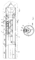
- the sensor unit 18 is located in a housing 28 which can be moved in the running tube 16 between a working position and a reference position by means of the cable 20. 2, the measuring probe 18 is released from the working position on the head 4.
- the connection is made in the working position by a plug connection 30 between the housing 28 and a connection box 33.
- the running tube 16 has a rectangular cross section.
- the housing 28 of the sensor unit 18 is provided with guide elements which move the housing 28 within the running tube 16 in a reproducible setting lead to the running tube 16. It is thereby achieved that the sensor unit 18 assumes reproducible positions within the running tube 16.
- the housing 28 of the sensor unit 18 is cylindrical.
- the guide elements include, for example, a skid 32, which is attached to the upper side of the housing 28 and guided on the upper side of a rectangularly shaped running tube 16, and rollers 38 and 40, which on radially protruding from the housing 28 of the measuring probe 18 in opposite corners the bottom of the rectangular tube 16 are guided.
- other common guide elements and other geometric shapes for the running tube 16 and the guideways or grooves formed therein can be selected in order to ensure that the housing 28 and thus the sensor unit 18 are always guided in the running tube 16 in a reproducible position.
- the skid 32 extends over a substantial part of the axial length of the housing 28 of the sensor unit 18 and is supported on springs 34.
- the springs 34 are supported in spring housings 36 in the middle on the upper side of the housing 28 of the sensor unit 18.
- two opposing pairs of rollers 38 and 40 are each provided near the axial ends of the housing 28.
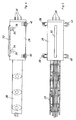
- a sensor unit 18 contains a two-axis, electrically tied dynamically tuned gyro 64 and two accelerometers 66 and 68 in a sensor block 70.
- the signals from the gyro 64 and the signals from the accelerometers 66 and 68 are connected to sensor electronics 72.
- the sensor electronics 72 contains the gyro operating electronics 74 and an analog-digital converter 76.
- the analog-digital converter 76 receives the acceleration signals from the accelerometers 66 and 68 and, via the gyro operating electronics 74, angular velocity signals from the gyro 64.
- the digitized signals are in one Signal processor 78 switched on. The signals are processed in the signal processor 78.
- a digital-analog conversion then takes place, the two analog output signals obtained being connected via lines 80 and 82 to torque generators of the dynamically tuned gyro 64.
- the Signal processor 78 digital output signals which correspond to the angular velocities around the input axes of the gyro 64.
- the power supply of the sensor unit 18 is designated.
- the arrangement corresponds approximately to EP-A-0 251 157 or US-A-4 823 626.
- the swirl axis of the dynamically tuned gyro is in the direction of advance.
- the input axes of the gyro are essentially horizontal and vertical.
- the gyro 64 thereby provides angular velocities about the pitch and yaw axes.
- the input axes of the accelerometers 66 and 68 are parallel to the one input axis falling in the direction of the pitch axis and to the swirl axis.
- the digital angular velocities at the output 84 are connected via the line 24 to the control unit 26 (FIG. 1) arranged on the surface of the earth.
- the control unit 26 contains a central computer 88 for navigation and control.
- the angular speeds of the gyro 64 and the accelerations of the accelerometers 66 and 68 are applied to the central computer 88 via an interface 90.
- the control unit 26 furthermore contains a path length measuring device 92.
- the path length measuring device 92 supplies the feed path of the sensor unit 18 on the basis of the length of the cable 20 which has been unwound from the drum 22. This feed path is also connected to the central computer 88 via the interface 90.
- the central computer 88 receives inputs from a display and operating unit 94.
- the power supply to the control unit 26 is designated 96.
- the central computer 88 determines angular velocities of the sensor unit 18 from the device-fixed angular velocity and acceleration signals in an earth-fixed one System. From these angular velocities, position angles or elements of the direction cosine matrix are calculated. The respective position of the sensor unit 18 can be determined from the position angles or the elements of the direction cosine matrix in connection with the feed path from the path length measuring device 92.
- the signal processing can be carried out in a similar manner to that described in DE-A-29 22 415.
- the control unit 26 supplies control signals for the propulsion head 4, which seek to keep the propulsion head 4 in a predetermined direction of advance but also work towards maintaining a predetermined path.
- the control unit 26 also receives from the path length measuring device of the drum 20 the data about the path covered from the unrolled cable length, so that the position of the sensor unit 18 and thus the position of the propulsion head 4 is precisely determined at all times by the navigation computer of the control unit 26 during the propulsion . If the propulsion of the Tunnel bore 8 over the length of the tube section 10A of the tunnel tube 10, the drum 22 is driven to wind up the cable 20, to detach the housing 28 of the sensor unit 18 from the plug connection 30 and the housing 28 with the sensor unit 18 in the running tube 16 to move from the working position into the reference position on the start and reference ramp 58. When the housing 28 of the sensor unit 18 has reached the reference position, the adjustment of the sensor unit 18 is checked.
- the pipe section 10B is inserted into the tunnel bore 8 and brought into engagement with the flange 10C at the rear end of the pipe section 10A already inserted.
- a further section of the running tube 16 is introduced in alignment with the section already present.
- the housing 28 is re-inserted into the elongated running tube 16 by unwinding the cable 20 from the drum 22 from the starting and reference ramp 58 via the telescopic tube and is moved in an exactly reproducible manner to the working position in which the plug connection 30 to the connection box 33 is restored.
- the jacking head 4 is then ready for further jacking in alignment with the desired axis 6 by a further pipe section length.
- the readjustment of the sensor unit 18 after the advance of the head 4 over a pipe section length has the advantage that a sensor unit 18 and thus a gyroscope of relatively small installation size and with relatively low accuracy requirements can be used, in particular with regard to long-term constancy.
- the sensor unit 18 can also detect a parallel offset of the propulsion head 4 to the desired axis 6.
- control device with the sensor unit 18 has been described above in connection with a tunnel boring machine 2 operating according to the shield construction. It is self-evident that such a control device can also be used in conjunction with tunnel boring machines operating according to other principles in the case of corresponding modifications which are readily accessible to the person skilled in the art.
Landscapes
- Life Sciences & Earth Sciences (AREA)
- Engineering & Computer Science (AREA)
- Geology (AREA)
- Mining & Mineral Resources (AREA)
- Physics & Mathematics (AREA)
- Environmental & Geological Engineering (AREA)
- Fluid Mechanics (AREA)
- General Life Sciences & Earth Sciences (AREA)
- Geochemistry & Mineralogy (AREA)
- Geophysics (AREA)
- Excavating Of Shafts Or Tunnels (AREA)
- Earth Drilling (AREA)
Applications Claiming Priority (2)
| Application Number | Priority Date | Filing Date | Title |
|---|---|---|---|
| DE4131673 | 1991-09-24 | ||
| DE4131673A DE4131673C2 (de) | 1991-09-24 | 1991-09-24 | Steuereinrichtung für eine Tunnelbohrmaschine |
Publications (3)
| Publication Number | Publication Date |
|---|---|
| EP0534338A2 true EP0534338A2 (fr) | 1993-03-31 |
| EP0534338A3 EP0534338A3 (en) | 1993-06-09 |
| EP0534338B1 EP0534338B1 (fr) | 1996-07-31 |
Family
ID=6441302
Family Applications (1)
| Application Number | Title | Priority Date | Filing Date |
|---|---|---|---|
| EP92116084A Expired - Lifetime EP0534338B1 (fr) | 1991-09-24 | 1992-09-21 | Dispositif de contrÔle pour une machine de forage de tunnels |
Country Status (3)
| Country | Link |
|---|---|
| EP (1) | EP0534338B1 (fr) |
| AT (1) | ATE141000T1 (fr) |
| DE (2) | DE4131673C2 (fr) |
Cited By (8)
| Publication number | Priority date | Publication date | Assignee | Title |
|---|---|---|---|---|
| WO2000034623A1 (fr) * | 1998-12-10 | 2000-06-15 | Sandvik Tamrock Oy | Procede et dispositif de forage de roches permettant de controler le forage de roches |
| US7579962B1 (en) * | 2005-05-17 | 2009-08-25 | At&T Intellectual Property Ii, L.P. | Duct mapping device using sonde |
| US7623961B2 (en) | 2002-11-22 | 2009-11-24 | Reduct | Method for determining a track of a geographical trajectory |
| CN103133765A (zh) * | 2011-11-28 | 2013-06-05 | 同济大学 | 地下非开挖管线施工实时自动导向方法及装置 |
| CN109630154A (zh) * | 2019-01-24 | 2019-04-16 | 华能西藏雅鲁藏布江水电开发投资有限公司 | 一种用于隧道掘进的掘进机器人及远程移动终端指挥系统 |
| CN111101851A (zh) * | 2019-12-19 | 2020-05-05 | 王晓腾 | 一种能够进行深度调节的城建电缆铺设用打洞装置 |
| CN112781590A (zh) * | 2020-12-17 | 2021-05-11 | 上海隧道工程有限公司 | 基于光纤陀螺仪的掘进机导向系统及方法 |
| CN115244270A (zh) * | 2020-04-28 | 2022-10-25 | 海瑞克股份公司 | 隧道掘进机 |
Families Citing this family (3)
| Publication number | Priority date | Publication date | Assignee | Title |
|---|---|---|---|---|
| DE19504969A1 (de) * | 1995-02-15 | 1996-08-22 | Bodenseewerk Geraetetech | Verfahren zur Steuerung einer Tunnelvortriebs-Maschine |
| DE19505855C1 (de) * | 1995-02-21 | 1996-02-08 | Dmt Gmbh | Vorrichtung zum Vermessen von Bohrlöchern |
| DE102006026561B3 (de) * | 2006-06-06 | 2008-01-03 | Herrenknecht Ag | Nordsucher für eine Tunnelvortriebsmaschine |
Family Cites Families (8)
| Publication number | Priority date | Publication date | Assignee | Title |
|---|---|---|---|---|
| DE2922415C2 (de) * | 1979-06-01 | 1988-08-18 | Bodenseewerk Gerätetechnik GmbH, 7770 Überlingen | Navigationsgerät für Landfahrzeuge |
| US4282470A (en) * | 1979-04-30 | 1981-08-04 | Northrop Corporation | Close loop control apparatus and method for a force rebalance transducer |
| AU1854783A (en) * | 1982-09-11 | 1984-03-15 | Nl Sperry-Sun Inc. | Surveying a borehole |
| CA1211506A (fr) * | 1983-02-22 | 1986-09-16 | Sundstrand Data Control, Inc. | Systeme de guidage intertiel dans un forage |
| DE3306070A1 (de) * | 1983-02-22 | 1984-08-23 | Witte Bohrtechnik GmbH, 3060 Stadthagen | Verfahren und vorrichtung zur herstellung eines unterirdischen rohrvortriebes |
| DE8337763U1 (de) * | 1983-12-31 | 1985-02-28 | Soltau, Gerd, Dr.-Ing., 2120 Lüneburg | Vorrichtung zum unterirdischen vorpressen von aus produktrohrschuessen gebildeten leitungsstrecken |
| DE3621953A1 (de) * | 1986-06-30 | 1988-01-14 | Bodenseewerk Geraetetech | Traegheitssensoranordnung |
| US4812977A (en) * | 1986-12-31 | 1989-03-14 | Sundstrand Data Control, Inc. | Borehole survey system utilizing strapdown inertial navigation |
-
1991
- 1991-09-24 DE DE4131673A patent/DE4131673C2/de not_active Revoked
-
1992
- 1992-09-21 EP EP92116084A patent/EP0534338B1/fr not_active Expired - Lifetime
- 1992-09-21 AT AT92116084T patent/ATE141000T1/de not_active IP Right Cessation
- 1992-09-21 DE DE59206842T patent/DE59206842D1/de not_active Expired - Fee Related
Cited By (12)
| Publication number | Priority date | Publication date | Assignee | Title |
|---|---|---|---|---|
| WO2000034623A1 (fr) * | 1998-12-10 | 2000-06-15 | Sandvik Tamrock Oy | Procede et dispositif de forage de roches permettant de controler le forage de roches |
| US6460630B2 (en) * | 1998-12-10 | 2002-10-08 | Sandvik Tamrock Oy | Method and rock drilling apparatus for controlling rock drilling |
| US7623961B2 (en) | 2002-11-22 | 2009-11-24 | Reduct | Method for determining a track of a geographical trajectory |
| EP2270429A2 (fr) | 2002-11-22 | 2011-01-05 | Reduct | Procédé de détermination de trace d'une trajectoire géographique. |
| US7579962B1 (en) * | 2005-05-17 | 2009-08-25 | At&T Intellectual Property Ii, L.P. | Duct mapping device using sonde |
| CN103133765A (zh) * | 2011-11-28 | 2013-06-05 | 同济大学 | 地下非开挖管线施工实时自动导向方法及装置 |
| CN103133765B (zh) * | 2011-11-28 | 2016-05-18 | 同济大学 | 地下非开挖管线施工实时自动导向方法及装置 |
| CN109630154A (zh) * | 2019-01-24 | 2019-04-16 | 华能西藏雅鲁藏布江水电开发投资有限公司 | 一种用于隧道掘进的掘进机器人及远程移动终端指挥系统 |
| CN109630154B (zh) * | 2019-01-24 | 2023-08-25 | 华能西藏雅鲁藏布江水电开发投资有限公司 | 一种用于隧道掘进的掘进机器人及远程移动终端指挥系统 |
| CN111101851A (zh) * | 2019-12-19 | 2020-05-05 | 王晓腾 | 一种能够进行深度调节的城建电缆铺设用打洞装置 |
| CN115244270A (zh) * | 2020-04-28 | 2022-10-25 | 海瑞克股份公司 | 隧道掘进机 |
| CN112781590A (zh) * | 2020-12-17 | 2021-05-11 | 上海隧道工程有限公司 | 基于光纤陀螺仪的掘进机导向系统及方法 |
Also Published As
| Publication number | Publication date |
|---|---|
| DE4131673C2 (de) | 1995-05-04 |
| DE59206842D1 (de) | 1996-09-05 |
| EP0534338A3 (en) | 1993-06-09 |
| ATE141000T1 (de) | 1996-08-15 |
| DE4131673A1 (de) | 1993-04-01 |
| EP0534338B1 (fr) | 1996-07-31 |
Similar Documents
| Publication | Publication Date | Title |
|---|---|---|
| DE19950340B4 (de) | Verfahren und Vorrichtung zum Messen des Verlaufs eines Bohrlochs | |
| DE2836859C2 (de) | Trägheitsrichtgerät | |
| DE68909355T2 (de) | Einrichtung zum Steuern der Lage eines selbstgetriebenen Bohrwerkzeuges. | |
| DE3120010C2 (fr) | ||
| EP0534338B1 (fr) | Dispositif de contrÔle pour une machine de forage de tunnels | |
| DE3328722A1 (de) | Bohrlochmessinstrument | |
| EP0511191A2 (fr) | Système pour mesurer la position d'une voie ferroviaire envers un point fixe | |
| DE2156110C3 (de) | Gerat zum Bestimmen des Rollwinkels eines Bohrkopfes | |
| DE2849633A1 (de) | Vorrichtung zum messen des azimuts und deer neigung einer bohrleitung | |
| DE2850090C2 (de) | Verfahren und Vorrichtung zum Messen von Azimut und Neigung eines Bohrlochs | |
| CH693246A5 (de) | Vermessungssystem mit einerträgheitsgestützten Messeinrichtung. | |
| DE3733553A1 (de) | Vorrichtung zum steuern einer schildvortriebsmaschine | |
| DE4439601C2 (de) | Verfahren zur Richtungssteuerung einer im Untertagebetrieb eingesetzten Maschine sowie zur Durchführung des Verfahrens geeignete Maschine | |
| DE69122971T2 (de) | Verfahren zum ausrichten eines vorschubarms an einer gesteinsbohrausrüstung, gesteinsbohrausrüstung und messgerät | |
| EP0344412B1 (fr) | Procédé et dispositif pour la mésure continue de la hauteur relative d'un objet allongé à enfoncer dans la terre | |
| EP0727561B1 (fr) | Procédé pour la commande d'une machine de creusement de tunnels | |
| DE102006027852B4 (de) | Gleismeßfahrzeug | |
| DE4333032A1 (de) | Vorrichtung zur Bestimmung der Lage und Ausrichtung einer Tunnelvortriebsmaschine | |
| DE19918215C2 (de) | Verfahren zur Messung von radialen Verformungen eines Tunnelausbaus und Vorrichtung zur Durchführung des Verfahrens | |
| DE20313252U1 (de) | Kanalortungssystem mit Kompass | |
| DE2756219C2 (de) | Verfahren und Vorrichtung zum Messen der Richtung eines Bohrloches | |
| DE19507346C2 (de) | Verfahren zum Steuern einer Vortriebsmaschine bei der Herstellung eines unterirdischen Hohlraumprofils sowie Einrichtung zur Durchführung des Verfahrens | |
| EP2539531A2 (fr) | Procédé et dispositif de forage | |
| DE3145129C1 (de) | Verfahren und Einrichtungen zur Positions- und Lageerfassung eines Bohrmolchs | |
| DE2523466A1 (de) | Kreiselkompass-ausrichtsystem |
Legal Events
| Date | Code | Title | Description |
|---|---|---|---|
| PUAI | Public reference made under article 153(3) epc to a published international application that has entered the european phase |
Free format text: ORIGINAL CODE: 0009012 |
|
| AK | Designated contracting states |
Kind code of ref document: A2 Designated state(s): AT BE CH DE DK ES FR GB GR IT LI NL SE |
|
| PUAL | Search report despatched |
Free format text: ORIGINAL CODE: 0009013 |
|
| AK | Designated contracting states |
Kind code of ref document: A3 Designated state(s): AT BE CH DE DK ES FR GB GR IT LI NL SE |
|
| 17P | Request for examination filed |
Effective date: 19931013 |
|
| 17Q | First examination report despatched |
Effective date: 19941228 |
|
| GRAG | Despatch of communication of intention to grant |
Free format text: ORIGINAL CODE: EPIDOS AGRA |
|
| GRAH | Despatch of communication of intention to grant a patent |
Free format text: ORIGINAL CODE: EPIDOS IGRA |
|
| GRAH | Despatch of communication of intention to grant a patent |
Free format text: ORIGINAL CODE: EPIDOS IGRA |
|
| GRAA | (expected) grant |
Free format text: ORIGINAL CODE: 0009210 |
|
| AK | Designated contracting states |
Kind code of ref document: B1 Designated state(s): AT BE CH DE DK ES FR GB GR IT LI NL SE |
|
| PG25 | Lapsed in a contracting state [announced via postgrant information from national office to epo] |
Ref country code: IT Free format text: LAPSE BECAUSE OF FAILURE TO SUBMIT A TRANSLATION OF THE DESCRIPTION OR TO PAY THE FEE WITHIN THE PRESCRIBED TIME-LIMIT;WARNING: LAPSES OF ITALIAN PATENTS WITH EFFECTIVE DATE BEFORE 2007 MAY HAVE OCCURRED AT ANY TIME BEFORE 2007. THE CORRECT EFFECTIVE DATE MAY BE DIFFERENT FROM THE ONE RECORDED. Effective date: 19960731 Ref country code: GR Free format text: LAPSE BECAUSE OF FAILURE TO SUBMIT A TRANSLATION OF THE DESCRIPTION OR TO PAY THE FEE WITHIN THE PRESCRIBED TIME-LIMIT Effective date: 19960731 Ref country code: NL Free format text: LAPSE BECAUSE OF FAILURE TO SUBMIT A TRANSLATION OF THE DESCRIPTION OR TO PAY THE FEE WITHIN THE PRESCRIBED TIME-LIMIT Effective date: 19960731 Ref country code: DK Effective date: 19960731 Ref country code: ES Free format text: THE PATENT HAS BEEN ANNULLED BY A DECISION OF A NATIONAL AUTHORITY Effective date: 19960731 |
|
| REF | Corresponds to: |
Ref document number: 141000 Country of ref document: AT Date of ref document: 19960815 Kind code of ref document: T |
|
| ET | Fr: translation filed | ||
| REF | Corresponds to: |
Ref document number: 59206842 Country of ref document: DE Date of ref document: 19960905 |
|
| REG | Reference to a national code |
Ref country code: CH Ref legal event code: NV Representative=s name: TROESCH SCHEIDEGGER WERNER AG |
|
| PG25 | Lapsed in a contracting state [announced via postgrant information from national office to epo] |
Ref country code: BE Effective date: 19960930 |
|
| PG25 | Lapsed in a contracting state [announced via postgrant information from national office to epo] |
Ref country code: SE Effective date: 19961031 |
|
| GBT | Gb: translation of ep patent filed (gb section 77(6)(a)/1977) |
Effective date: 19961030 |
|
| NLV1 | Nl: lapsed or annulled due to failure to fulfill the requirements of art. 29p and 29m of the patents act | ||
| PLBE | No opposition filed within time limit |
Free format text: ORIGINAL CODE: 0009261 |
|
| 26N | No opposition filed | ||
| PGFP | Annual fee paid to national office [announced via postgrant information from national office to epo] |
Ref country code: FR Payment date: 19980820 Year of fee payment: 7 |
|
| PGFP | Annual fee paid to national office [announced via postgrant information from national office to epo] |
Ref country code: GB Payment date: 19980907 Year of fee payment: 7 |
|
| PGFP | Annual fee paid to national office [announced via postgrant information from national office to epo] |
Ref country code: AT Payment date: 19980914 Year of fee payment: 7 |
|
| PGFP | Annual fee paid to national office [announced via postgrant information from national office to epo] |
Ref country code: CH Payment date: 19981201 Year of fee payment: 7 |
|
| PG25 | Lapsed in a contracting state [announced via postgrant information from national office to epo] |
Ref country code: GB Free format text: LAPSE BECAUSE OF NON-PAYMENT OF DUE FEES Effective date: 19990921 Ref country code: AT Free format text: LAPSE BECAUSE OF NON-PAYMENT OF DUE FEES Effective date: 19990921 |
|
| PG25 | Lapsed in a contracting state [announced via postgrant information from national office to epo] |
Ref country code: CH Free format text: LAPSE BECAUSE OF NON-PAYMENT OF DUE FEES Effective date: 19990930 Ref country code: LI Free format text: LAPSE BECAUSE OF NON-PAYMENT OF DUE FEES Effective date: 19990930 |
|
| GBPC | Gb: european patent ceased through non-payment of renewal fee |
Effective date: 19990921 |
|
| REG | Reference to a national code |
Ref country code: CH Ref legal event code: PL |
|
| PG25 | Lapsed in a contracting state [announced via postgrant information from national office to epo] |
Ref country code: FR Free format text: LAPSE BECAUSE OF NON-PAYMENT OF DUE FEES Effective date: 20000531 |
|
| REG | Reference to a national code |
Ref country code: FR Ref legal event code: ST |
|
| PGFP | Annual fee paid to national office [announced via postgrant information from national office to epo] |
Ref country code: DE Payment date: 20041122 Year of fee payment: 13 |
|
| PG25 | Lapsed in a contracting state [announced via postgrant information from national office to epo] |
Ref country code: DE Free format text: LAPSE BECAUSE OF NON-PAYMENT OF DUE FEES Effective date: 20060401 |