EP0534645A1 - Dispositifs et procédé pour calibrer d'un module de commande de suspension - Google Patents
Dispositifs et procédé pour calibrer d'un module de commande de suspension Download PDFInfo
- Publication number
- EP0534645A1 EP0534645A1 EP92308257A EP92308257A EP0534645A1 EP 0534645 A1 EP0534645 A1 EP 0534645A1 EP 92308257 A EP92308257 A EP 92308257A EP 92308257 A EP92308257 A EP 92308257A EP 0534645 A1 EP0534645 A1 EP 0534645A1
- Authority
- EP
- European Patent Office
- Prior art keywords
- vehicle
- signal
- deviation
- height
- control module
- Prior art date
- Legal status (The legal status is an assumption and is not a legal conclusion. Google has not performed a legal analysis and makes no representation as to the accuracy of the status listed.)
- Granted
Links
Images


Classifications
-
- F—MECHANICAL ENGINEERING; LIGHTING; HEATING; WEAPONS; BLASTING
- F16—ENGINEERING ELEMENTS AND UNITS; GENERAL MEASURES FOR PRODUCING AND MAINTAINING EFFECTIVE FUNCTIONING OF MACHINES OR INSTALLATIONS; THERMAL INSULATION IN GENERAL
- F16F—SPRINGS; SHOCK-ABSORBERS; MEANS FOR DAMPING VIBRATION
- F16F9/00—Springs, vibration-dampers, shock-absorbers, or similarly-constructed movement-dampers using a fluid or the equivalent as damping medium
- F16F9/32—Details
- F16F9/3264—Arrangements for indicating, e.g. fluid level; Arrangements for checking dampers
-
- B—PERFORMING OPERATIONS; TRANSPORTING
- B60—VEHICLES IN GENERAL
- B60G—VEHICLE SUSPENSION ARRANGEMENTS
- B60G17/00—Resilient suspensions having means for adjusting the spring or vibration-damper characteristics, for regulating the distance between a supporting surface and a sprung part of vehicle or for locking suspension during use to meet varying vehicular or surface conditions, e.g. due to speed or load
- B60G17/015—Resilient suspensions having means for adjusting the spring or vibration-damper characteristics, for regulating the distance between a supporting surface and a sprung part of vehicle or for locking suspension during use to meet varying vehicular or surface conditions, e.g. due to speed or load the regulating means comprising electric or electronic elements
- B60G17/018—Resilient suspensions having means for adjusting the spring or vibration-damper characteristics, for regulating the distance between a supporting surface and a sprung part of vehicle or for locking suspension during use to meet varying vehicular or surface conditions, e.g. due to speed or load the regulating means comprising electric or electronic elements characterised by the use of a specific signal treatment or control method
- B60G17/0185—Resilient suspensions having means for adjusting the spring or vibration-damper characteristics, for regulating the distance between a supporting surface and a sprung part of vehicle or for locking suspension during use to meet varying vehicular or surface conditions, e.g. due to speed or load the regulating means comprising electric or electronic elements characterised by the use of a specific signal treatment or control method for failure detection
-
- B—PERFORMING OPERATIONS; TRANSPORTING
- B60—VEHICLES IN GENERAL
- B60G—VEHICLE SUSPENSION ARRANGEMENTS
- B60G2204/00—Indexing codes related to suspensions per se or to auxiliary parts
- B60G2204/10—Mounting of suspension elements
- B60G2204/11—Mounting of sensors thereon
-
- B—PERFORMING OPERATIONS; TRANSPORTING
- B60—VEHICLES IN GENERAL
- B60G—VEHICLE SUSPENSION ARRANGEMENTS
- B60G2204/00—Indexing codes related to suspensions per se or to auxiliary parts
- B60G2204/40—Auxiliary suspension parts; Adjustment of suspensions
- B60G2204/422—Links for mounting suspension elements
-
- B—PERFORMING OPERATIONS; TRANSPORTING
- B60—VEHICLES IN GENERAL
- B60G—VEHICLE SUSPENSION ARRANGEMENTS
- B60G2400/00—Indexing codes relating to detected, measured or calculated conditions or factors
- B60G2400/25—Stroke; Height; Displacement
- B60G2400/252—Stroke; Height; Displacement vertical
-
- B—PERFORMING OPERATIONS; TRANSPORTING
- B60—VEHICLES IN GENERAL
- B60G—VEHICLE SUSPENSION ARRANGEMENTS
- B60G2401/00—Indexing codes relating to the type of sensors based on the principle of their operation
Definitions
- the present invention relates generally to automotive suspension control modules. More particularly, the present invention relates to an apparatus and method for calibrating an automotive suspension control module to within a preselected tolerance of a predetermined ride height.
- Automotive suspensions employing adjustable suspension units typically utilise one or more sensors for detecting the position of one or more portions of the suspension with respect to either another part of the suspension itself or another part of the chassis of the vehicle.
- sensors for detecting the position of one or more portions of the suspension with respect to either another part of the suspension itself or another part of the chassis of the vehicle.
- the ride height of the vehicle in order to determine whether correction of the ride height is required.
- an adjustable suspension unit may be given the command to increase the ride height.
- the adjustable suspension unit may be given the command to lower or decrease the ride height.
- U.S. Patent No. 4,517,832 assigned to the assignee of the present invention, discloses a method of diagnosing an air suspension system for possible faults within the system.
- the patent discloses the steps of energising the air suspension units to the fully extended or rebound position and reading the output signals of the height sensors at that point to check whether the output signal corresponds correctly to the rebound position.
- the patent further discloses similar steps in checking the height sensor output signal when the air suspension unit is fully deflated as well as at a predetermined trim height.
- the patent does not teach any method for calibrating the vehicle suspension control module in the event that the height sensor output signal does not correctly correspond to the actual ride height of the vehicle.
- analog height sensors which measure the distance between the sprung and unsprung mass of the vehicle in continuous increments, it is especially important that the suspension control module be calibrated to correspond the sensor output signal to the actual ride height of the vehicle.
- suspension control module and height sensors may be calibrated without the need for lock-in-place brackets or other tooling.
- an apparatus for calibrating a suspension control module of a vehicle to within a preselected tolerance of a predetermined ride height the vehicle having at least one adjustable suspension unit interposed between a sprung and unsprung vehicle mass, comprises first means for measuring a first distance corresponding to an actual ride height of a vehicle and for generating a first signal representative thereof and second means for measuring a second distance between the sprung and unsprung vehicle mass and for generating a second signal representative thereof.
- the apparatus further comprises processor means operatively associated with the first and second measuring means for comparing the first and second signals and for calculating a deviation between the signals, the processor means generating a third signal corresponding to the deviation and storing the deviation in the suspension control module.
- the processor means is further operative to adjust the second signal by the deviation to provide correlation between the second signal and the actual ride height of the vehicle.
- a method for calibrating a suspension control module of a vehicle to within a preselected tolerance of a predetermined ride height the vehicle having a suspension system including a plurality of adjustable suspension units interposed between the sprung and unsprung vehicle mass.
- the method comprises the steps of:
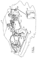
- Figure 1 shows a vehicle 10 positioned above a garage pit 11 subjacent the floor of a garage or manufacturing facility. An operator is stationed in the pit 11 to make various adjustments to the vehicle after the vehicle has been manufactured or for servicing the vehicle 10.
- the vehicle in Figure 1 is equipped in conventional fashion with adjustable air spring suspension units 14 which serve to control the vertical motion of the wheel and tire assemblies 12.
- the air springs are supplied with compressed air by compressor 22 which is electrically powered by the vehicle battery.
- Each of the adjustable suspension units 14 is operatively connected with and controlled by suspension control module 15.
- the control module includes a microprocessor and may be arranged according to a number of different architectures. Those skilled in the art will appreciate in view of this disclosure that each such architecture could generally include an input-output control circuit (I/O) for exchanging data with external devices in a random access memory (RAM) and for temporarily holding data while the data are being processed. Control programs including unit commands will be sequentially read from a read-only memory (ROM). Unit commands will be executed by a central processing unit (CPU).
- FIG. 1 represents merely one preferred embodiment of the present invention, it being understood that this invention is suitable for use with other adjustable suspension units such as air-hydraulic or hydraulic load-bearing units or combinations of adjustable load bearing and adjustable damping units such as those known in the art.
- a system according to this invention could be employed in conjunction with the control of damping, or spring rate, or both functions. This system could also be employed in conjunction with adjustable suspension units having variable ride height or spring load control characteristics.
- the apparatus of the present invention further includes a vehicle height measuring device unit 24, such as a "run out compensation static wheel alignment adjuster" manufactured by the Anzen Motor Car Company Ltd. and as disclosed in U.S. Patent Nos. 3,453,740; 4,962,664; and 4,901,560, the disclosures of which are herein incorporated by reference.
- the vehicle height measuring device 24 is positioned over the pit 11 of the manufacturing facility and includes a front and rear set of rollers upon which the front and rear vehicle wheels are placed, respectively.
- the measurement device 24 includes means for measuring the actual vehicle ride height.
- Such means may include a linear variable differential transformer 25 electrically connected with the measurement device and which physically contacts the chassis of the vehicle or some other part of the vehicle which can be mathematically related to the vehicle height, such as the vehicle bumper.
- chassis refers to not only a body-on-chassis construction but also a unibody construction.
- the means for measuring the actual vehicle ride height may also include a sonic transducer, such as shown in Figure 3, or a laser transducer which generates a signal reflected off part of the vehicle chassis and received by the transducer to determine mathematically the distance between the vehicle and the surface upon which the vehicle is setting. Such information is necessary in order to calibrate the vehicle height sensor output signals.
- the roadwheel and tire assembly 12 is rotatably supported upon wheel carrier 26, and in each case, a lower control arm 30 is pivotally connected to the wheel carrier 26 at its outboard end and to the body or chassis of the vehicle 16 at its inboard end.
- a lower control arm 30 is pivotally connected to the wheel carrier 26 at its outboard end and to the body or chassis of the vehicle 16 at its inboard end.
- an upper control arm 28 and coil spring 29 complete the suspension geometry.
- Upper control arm 28 is pivotally attached at its outboard end to the wheel carrier 26 and at its inboard end to the chassis 16.
- the suspension unit shown in Figure 3 further includes an adjustable suspension unit 14 which may have adjustable damping or adjustable load carrying capabilities or both.
- Figure 3 further illustrates use of a position sensor 20 which may comprise a linear variable differential transformer (hereinafter "LVDT"), a Hall Effect device or one of a variety of other devices suitable for use according to the present invention.
- LVDT linear variable differential transformer
- the sensor Regardless of the type of suspension position sensor chosen, the sensor generates a signal representing the vertical position of the wheel and tire assembly 12 as the wheel and tire moves through jounce and rebound directions.
- the height sensor 20 may be of an analog type, generating an exact signal corresponding to each position of the roadwheel and tire assembly with respect to the body or chassis of the vehicle as opposed to known digital sensors which generate a logic "1" or "0" as the roadwheel and tire assembly pass through specific jounce or rebound defined areas.
- Figure 4 illustrates an alternative suspension which may be controlled by an apparatus according to the present invention.
- an adjustable suspension unit 14 is employed for producing damping within the suspension system and is also capable of controlling the height of the vehicle.
- the embodiment of Figure 4 includes a rotary height sensor 20 which may be configures using Hall Effect switches. This sensor utilises a link and crank arm for converting the up and down motion of the suspension control arm 30 into a rotary motion which may be input into the sensor.
- Sensor 20 is described in U.S. Patent No. 4,822,063, which is assigned to the assignee of the present invention and which is hereby incorporated by reference.
- Other types of position sensors comprising either variable resistance, variable reluctance, variable capacitance, or Hall Effect sensors or other types of sensor known to those skilled in the art and suggested by this disclosure may be utilised as well.
- the apparatus of the present invention further includes a processor 32 for receiving information from the ride height measuring unit 24 and the vehicle height sensors 20 via the suspension control module 15.
- the processor 32 compares the height sensor output signal and the actual ride height signal generated by the measurement device and calculates a deviation between the signal values. The processor then adjusts the height sensor output signal by this deviation so that the adjusted height sensor output signal corresponds to the actual vehicle ride height. After an iterative check to determine that the height sensor output signal corresponds to the actual ride height, the processor 32 stores this deviation into the memory of the suspension control module to correlate the height sensor output signal to the actual vehicle ride height. In this respect, proper functioning of the different height control or ride control strategies for the vehicle can be employed because there is proper correlation between the height sensor signal and the actual vehicle ride height.
- the control module is calibrated while the position sensor is on the vehicle instead of at the point of manufacture because vehicle attachments are the greatest source of variability of the sensor output signal. For example, if two sensors are installed successively in the same vehicle and the suspension adjusted until the sensor output is 2.5 volts, the suspension position may vary by 0.1 inches. If, however, the same sensors installed on two different vehicles and the suspension adjusted until the sensor output is 2.5 volts, the suspension positions will vary by a much greater amount, perhaps the 0.5 inches.
- Figure 5 shows a logic flow block diagram of a method of the present invention for calibrating a suspension control module of a vehicle to within a preselected tolerance of a predetermined ride height.
- the vehicle 10 includes a plurality of suspension unit 14 which are interposed between the sprung and unsprung vehicle mass, the sprung vehicle mass being the chassis 16 while the unsprung mass includes, inter alia , suspension components such as the lower control arm 30 and the tire and wheel assembly 12.
- the first step of the method is to drive the vehicle 10 onto the Anzen machine as shown in block 42.
- the method of the present invention may be performed with devices other than an Anzen machine, it being necessary only to have a device which can measure the actual vehicle ride height and generate a signal corresponding to that height.
- the actual vehicle ride height is measured by any of the measuring devices described above, such as the sonic transducer or a linear variable displacement transducer, and that signal is sent to the processor 32.
- the height sensors 20 measure the distance between their respective mounting points between the sprung and unsprung vehicle mass and that signal is sent to the processor 32 as well.
- the processor 32 then converts the actual vehicle ride height position into a value equivalent to that received by the height sensor, such as voltage.
- the processor After calculating the deviation or the difference between the actual ride height signal and the height sensor output signal, the processor, at block 50, adjusts the height sensor output signal by an amount equal to the difference between the two signals so that there is a correspondence or correlation between the height sensor output signal and the actual ride height of the vehicle. It can be assumed throughout the method of the present invention that the height sensors utilised in a vehicle employing the present invention, especially those of analog type sensors, may be incorrectly calibrated at their point of manufacture or that the amount of discrepancy between the mounting points on the height sensors at the various locations within the vehicle tend to be off due to the bending or skewing of the vehicle body as explained above. As such, the height sensor output signal may not necessarily correspond to the actual vehicle ride height.
- the processor actuates all of the suspension units to put the vehicle at its desired trim height at block 52.
- Trim height in a vehicle is typically 18 inches (0.46 meters) with a predetermined tolerance of plus or minus 0.5 inches (12.7 mm). It should be readily apparent to those skilled in the art that the present invention is not meant to be limited to these values, that each vehicle may correspondingly have a different trim ride height.
- the processor does a reiterative check at block 54 to determine whether the height sensor output signal is correlated to the actual vehicle ride height. If it is, the deviation is permanently burned into a non-volatile memory of the suspension control module at block 56. It should be readily apparent to those skilled in the art that other types of memories within the suspension control module could be utilised in place of the non-volatile memory.
- the present invention is not meant to be limited solely to the suspension control module having a non-volatile memory.
- a plot of the transfer function used in calibrating a suspension control module according to the method of the present invention is designated by line G.
- Output value such as voltage
- actual ride height in millimetres
- x-axis the transfer height
- this trim ride height position has an equivalent output value or voltage
- point A on the y-axis as determined by the transfer function
- the transfer function above allows the signal from the ride height measurement device to be converted into a signal having the same units of measurement as are output from the height sensors, such as voltage.
- Other types of signals may be used as well in the present invention, such as pulse width modulated signals, frequency modulated signals, digital, non-linear or current loop signals.
- the processor utilises the transfer function, line G, to calculate an equivalent output value, shown as point F on the y-axis.
- the height sensors 20 may be generating a signal having an output value corresponding to point D, y-axis, which corresponds to an actual ride height position shown at point B, x-axis, even though the actual vehicle height is at point C, x-axis.
- This output value at B exceeds the trim output value, point A, y-axis, which indicates to the suspension control module that the height of the vehicle should be reduced, whereas in actuality, the vehicle height needs to be increased.
- the processor of the present invention receives the signal from the ride height measuring device, point C, converts it to an equivalent output value, F, and receives the height sensor output signal, point D. The processor then calculates the deviation between the two values, corresponding to an output value equal to D minus F. In the present example, this deviation would be a negative value since the actual ride height is lower than the height sensor output signal.
- G mX + (D - F) .
- the processor then stores this new transfer function into the memory of the suspension control module so that the suspension control module is calibrated to correlate the height sensor output signal to the actual vehicle ride height. All future readings of the height sensor signals will then be offset by the deviation to maintain a correct correlation between the actual vehicle ride height and height sensor signal value.
Landscapes
- Engineering & Computer Science (AREA)
- Mechanical Engineering (AREA)
- General Engineering & Computer Science (AREA)
- Vehicle Body Suspensions (AREA)
Applications Claiming Priority (2)
| Application Number | Priority Date | Filing Date | Title |
|---|---|---|---|
| US765803 | 1991-09-26 | ||
| US07/765,803 US5267466A (en) | 1991-09-26 | 1991-09-26 | Apparatus and method for calibrating a suspension control module |
Publications (2)
| Publication Number | Publication Date |
|---|---|
| EP0534645A1 true EP0534645A1 (fr) | 1993-03-31 |
| EP0534645B1 EP0534645B1 (fr) | 1995-12-20 |
Family
ID=25074529
Family Applications (1)
| Application Number | Title | Priority Date | Filing Date |
|---|---|---|---|
| EP92308257A Expired - Lifetime EP0534645B1 (fr) | 1991-09-26 | 1992-09-10 | Dispositifs et procédé pour calibrer d'un module de commande de suspension |
Country Status (3)
| Country | Link |
|---|---|
| US (1) | US5267466A (fr) |
| EP (1) | EP0534645B1 (fr) |
| DE (1) | DE69206936T2 (fr) |
Cited By (7)
| Publication number | Priority date | Publication date | Assignee | Title |
|---|---|---|---|---|
| DE19517972A1 (de) * | 1994-05-18 | 1995-11-30 | Delphi France Automotive Sys | Warnschaltung für ein Niveauregulierungssteuersystem |
| EP0686518A3 (fr) * | 1994-06-10 | 1996-07-03 | Gen Motors Corp | Système de régulation du niveau d'un véhicule |
| WO1998057130A1 (fr) * | 1997-06-13 | 1998-12-17 | Lord Corporation | Procede d'autocalibrage d'une suspension a amortisseur reglable |
| EP1063497A1 (fr) * | 1999-06-24 | 2000-12-27 | Continental Aktiengesellschaft | Méthode pour déterminer la distance de séparation de deux points de référence qui se déplacent l'un par rapport à l' autre entre une limite inférieure et une limite supérieure |
| EP1983325A3 (fr) * | 2007-04-18 | 2010-11-03 | Dr. Ing. h.c. F. Porsche AG | Dispositif de régulation de la position d'un véhicule automobile |
| WO2017190818A1 (fr) * | 2016-05-04 | 2017-11-09 | Wabco Gmbh | Dispositif de régulation de niveau électronique pour véhicules à suspension pneumatique, procédé et appareil de commande pour régulation de niveau électronique |
| CN113155486A (zh) * | 2021-05-31 | 2021-07-23 | 奇瑞汽车股份有限公司 | 动力总成悬置系统的耐久度模拟试验方法和系统 |
Families Citing this family (27)
| Publication number | Priority date | Publication date | Assignee | Title |
|---|---|---|---|---|
| US6148252A (en) * | 1992-04-10 | 2000-11-14 | Unisia Jecs Corporation | Automotive suspension control system utilizing variable damping force shock absorber |
| US5461564A (en) * | 1994-08-09 | 1995-10-24 | Ford Motor Company | Apparatus and method for calibrating vehicle ride height |
| US5999868A (en) * | 1996-02-26 | 1999-12-07 | Board Of Regents The University Of Texas System | Constant force suspension, near constant force suspension, and associated control algorithms |
| JP3053570B2 (ja) * | 1996-04-26 | 2000-06-19 | 日産アルティア株式会社 | ローリングサスペンションテスタ |
| DE19853126B4 (de) * | 1998-11-18 | 2005-03-03 | Daimlerchrysler Ag | Verfahren zur Niveauregelung und Radfahrzeug mit einem Niveauregelsystem |
| DE10126458C2 (de) * | 2001-05-31 | 2003-06-12 | Daimler Chrysler Ag | Dichtheits- und Funktionsprüfung eines Sperrventils in einer pneumatischen Federung |
| US8306696B2 (en) | 2003-04-17 | 2012-11-06 | Driveright Holdings, Ltd. | Method and system for aligning a vehicle with an artificial horizon |
| WO2005005178A2 (fr) * | 2003-04-17 | 2005-01-20 | Bfs Diversified Products, Llc | Procede et systeme d'alignement d'un vehicule a l'arret a l'aide d'un horizon artificiel |
| US7744099B2 (en) * | 2004-11-04 | 2010-06-29 | Driveright Holdings, Ltd. | Method and system for adjusting a vehicle aligned with an artificial horizon |
| US7991521B2 (en) * | 2006-02-01 | 2011-08-02 | Jervis B. Webb Company | Variable path automated guided vehicle |
| US7398668B2 (en) * | 2006-06-27 | 2008-07-15 | Bfs Diversified Products, Llc | Weight sensing system and method for vehicles with non-fluid springs |
| DE102006043607A1 (de) * | 2006-09-16 | 2008-03-27 | Continental Aktiengesellschaft | Verfahren zur Diagnose der Funktion einer Niveauregelanlage eines Kraftfahrzeugs |
| DE102007006552A1 (de) | 2007-02-09 | 2008-08-14 | Continental Aktiengesellschaft | Verfahren zur Überprüfung der Kopplung zweier zueinander beweglicher Bezugspunkte |
| US8155835B2 (en) * | 2008-02-21 | 2012-04-10 | Driveright Holdings, Ltd. | Vehicle chassis height adjustment method and system |
| US8160774B2 (en) * | 2008-10-15 | 2012-04-17 | GM Global Technology Operations LLC | Vehicular actuator system |
| US8174377B2 (en) * | 2008-11-14 | 2012-05-08 | GM Global Technology Operations LLC | Suspension height sensor |
| US8175770B2 (en) * | 2008-11-17 | 2012-05-08 | GM Global Technology Operations LLC | Height sensing system for a vehicular suspension assembly |
| US8143766B2 (en) * | 2009-02-27 | 2012-03-27 | GM Global Technology Operations LLC | Harvesting energy from vehicular vibrations using piezoelectric devices |
| US8253281B2 (en) * | 2009-02-27 | 2012-08-28 | GM Global Technology Operations LLC | Energy harvesting apparatus incorporated into shock absorber |
| US7936113B2 (en) * | 2009-02-27 | 2011-05-03 | GM Global Technology Operations LLC | Harvesting energy from vehicular vibrations using piezoelectric devices |
| US8063498B2 (en) * | 2009-02-27 | 2011-11-22 | GM Global Technology Operations LLC | Harvesting energy from vehicular vibrations |
| US7956797B2 (en) * | 2009-03-09 | 2011-06-07 | GM Global Technology Operations LLC | System and method for measuring a relative distance between vehicle components using ultra-wideband techniques |
| US8614518B2 (en) * | 2009-10-14 | 2013-12-24 | GM Global Technology Operations LLC | Self-powered vehicle sensor systems |
| US11145142B2 (en) * | 2016-09-06 | 2021-10-12 | International Business Machines Corporation | Detection of road surface defects |
| CN114166133B (zh) * | 2021-11-24 | 2023-05-23 | 岚图汽车科技有限公司 | 一种高度传感器标定方法、装置、设备及可读存储介质 |
| DE102023204168A1 (de) * | 2023-05-05 | 2024-11-07 | Zf Friedrichshafen Ag | Kalibrieren von elektronischen Stoßdämpfern |
| US20250170866A1 (en) * | 2023-11-29 | 2025-05-29 | Fox Factory, Inc. | Rapid ride height adjustment system |
Citations (3)
| Publication number | Priority date | Publication date | Assignee | Title |
|---|---|---|---|---|
| US4517832A (en) * | 1984-01-12 | 1985-05-21 | Ford Motor Company | Air suspension system service diagnostics |
| EP0220115A1 (fr) * | 1985-10-11 | 1987-04-29 | Jaeger | Procédé de contrôle d'une suspension de véhicule par mesure du coefficient de frottement de l'amortisseur et dispositif pour la mise en oeuvre du procédé |
| US4822063A (en) * | 1987-11-27 | 1989-04-18 | Ford Motor Company | Automotive suspension control system including suspension position sensor |
Family Cites Families (19)
| Publication number | Priority date | Publication date | Assignee | Title |
|---|---|---|---|---|
| DE324417C (de) * | 1919-07-09 | 1920-08-28 | Gustav Simmig | Vorrichtung zum selbsttaetigen Schliessen von staendig auf Zuschlagen beeinflussten,aber von einer Magnetsperrung offen gehaltenen Fensterfluegeln mittels sich an-sammelnden Regenwassers |
| US3453740A (en) * | 1966-08-23 | 1969-07-08 | Anzen Motor Car | Apparatus for checking the wheel alignment of an automobile |
| US4483546A (en) * | 1981-04-08 | 1984-11-20 | Lucas Industries Public Limited Company | Self-levelling suspension |
| JPS58174007A (ja) * | 1982-04-06 | 1983-10-13 | Nissan Motor Co Ltd | 自動車高調整装置 |
| JPS59230849A (ja) * | 1983-06-14 | 1984-12-25 | Toyoda Gosei Co Ltd | ステアリングホイ−ルの衝撃エネルギ−吸収構造体 |
| JPS6092914A (ja) * | 1983-10-27 | 1985-05-24 | Nippon Denso Co Ltd | 車高制御装置 |
| JPS6092913A (ja) * | 1983-10-27 | 1985-05-24 | Nippon Denso Co Ltd | 車高制御装置 |
| JPS61178212A (ja) * | 1985-02-04 | 1986-08-09 | Nippon Denso Co Ltd | 車高制御装置 |
| JPH0641241B2 (ja) * | 1985-05-20 | 1994-06-01 | 日野自動車工業株式会社 | トラックの荷台の高さ調整装置 |
| GB8521135D0 (en) * | 1985-08-23 | 1985-10-02 | Holset Engineering Co | Measuring device calibration |
| JPH075009B2 (ja) * | 1985-10-22 | 1995-01-25 | トヨタ自動車株式会社 | 車輌用車高調整装置 |
| DE3542974A1 (de) * | 1985-12-05 | 1987-06-11 | Wabco Westinghouse Fahrzeug | Niveauregeleinrichtung fuer fahrzeuge mit luftfedern |
| JPH0737203B2 (ja) * | 1986-05-08 | 1995-04-26 | 日産自動車株式会社 | 車高制御装置 |
| NO174785C (no) * | 1986-07-09 | 1994-07-06 | Norske Stats Oljeselskap | Anordning med ventilfunksjon |
| JPS63179212U (fr) * | 1987-05-13 | 1988-11-21 | ||
| CA1328038C (fr) * | 1987-05-20 | 1994-03-29 | Akira Hirano | Appareil de mesure a rouleaux de serrage multiples servant a verifier l'alignement des roues |
| US4838574A (en) * | 1987-12-14 | 1989-06-13 | Ford Motor Company | Hybrid suspension position and body velocity sensing system for automotive suspension control system |
| US5083454A (en) * | 1987-12-28 | 1992-01-28 | Ford Motor Company | Force-operated suspension position sensor for automotive vehicle |
| DE3919040A1 (de) * | 1989-06-10 | 1990-12-13 | Porsche Ag | Verfahren und vorrichtung zur justierung einer hoehenstands-regelanlage eines fahrzeugs |
-
1991
- 1991-09-26 US US07/765,803 patent/US5267466A/en not_active Expired - Lifetime
-
1992
- 1992-09-10 DE DE69206936T patent/DE69206936T2/de not_active Expired - Fee Related
- 1992-09-10 EP EP92308257A patent/EP0534645B1/fr not_active Expired - Lifetime
Patent Citations (3)
| Publication number | Priority date | Publication date | Assignee | Title |
|---|---|---|---|---|
| US4517832A (en) * | 1984-01-12 | 1985-05-21 | Ford Motor Company | Air suspension system service diagnostics |
| EP0220115A1 (fr) * | 1985-10-11 | 1987-04-29 | Jaeger | Procédé de contrôle d'une suspension de véhicule par mesure du coefficient de frottement de l'amortisseur et dispositif pour la mise en oeuvre du procédé |
| US4822063A (en) * | 1987-11-27 | 1989-04-18 | Ford Motor Company | Automotive suspension control system including suspension position sensor |
Cited By (11)
| Publication number | Priority date | Publication date | Assignee | Title |
|---|---|---|---|---|
| DE19517972A1 (de) * | 1994-05-18 | 1995-11-30 | Delphi France Automotive Sys | Warnschaltung für ein Niveauregulierungssteuersystem |
| DE19517972C2 (de) * | 1994-05-18 | 1998-04-16 | Delphi France Automotive Sys | Warnschaltung für ein Niveauregulierungssteuersystem |
| EP0686518A3 (fr) * | 1994-06-10 | 1996-07-03 | Gen Motors Corp | Système de régulation du niveau d'un véhicule |
| WO1998057130A1 (fr) * | 1997-06-13 | 1998-12-17 | Lord Corporation | Procede d'autocalibrage d'une suspension a amortisseur reglable |
| US5964455A (en) * | 1997-06-13 | 1999-10-12 | Lord Corporation | Method for auto-calibration of a controllable damper suspension system |
| EP1063497A1 (fr) * | 1999-06-24 | 2000-12-27 | Continental Aktiengesellschaft | Méthode pour déterminer la distance de séparation de deux points de référence qui se déplacent l'un par rapport à l' autre entre une limite inférieure et une limite supérieure |
| US6369583B1 (en) | 1999-06-24 | 2002-04-09 | Continental Aktiengesellschaft | Method for determining the distance of two reference points movable between a lower distance limit and an upper distance limit |
| EP1983325A3 (fr) * | 2007-04-18 | 2010-11-03 | Dr. Ing. h.c. F. Porsche AG | Dispositif de régulation de la position d'un véhicule automobile |
| WO2017190818A1 (fr) * | 2016-05-04 | 2017-11-09 | Wabco Gmbh | Dispositif de régulation de niveau électronique pour véhicules à suspension pneumatique, procédé et appareil de commande pour régulation de niveau électronique |
| US10967696B2 (en) | 2016-05-04 | 2021-04-06 | Wabco Europe Bvba | Electronic level control device for air-suspended vehicles, method and control device for electronic level control |
| CN113155486A (zh) * | 2021-05-31 | 2021-07-23 | 奇瑞汽车股份有限公司 | 动力总成悬置系统的耐久度模拟试验方法和系统 |
Also Published As
| Publication number | Publication date |
|---|---|
| US5267466A (en) | 1993-12-07 |
| EP0534645B1 (fr) | 1995-12-20 |
| DE69206936T2 (de) | 1996-05-23 |
| DE69206936D1 (de) | 1996-02-01 |
Similar Documents
| Publication | Publication Date | Title |
|---|---|---|
| EP0534645B1 (fr) | Dispositifs et procédé pour calibrer d'un module de commande de suspension | |
| US5461564A (en) | Apparatus and method for calibrating vehicle ride height | |
| US6293562B1 (en) | Method and apparatus for controlling ride height of a wheeled vehicle | |
| CA2410003C (fr) | Systeme de correction de hauteur et capteur associe | |
| JP3309086B2 (ja) | 車体と車輪間の距離測定装置 | |
| US5373445A (en) | Method and apparatus for determining dynamic force within an air spring suspension | |
| US5031934A (en) | Vehicular suspension position sensor and method of calibration | |
| EP0318139B1 (fr) | Système de réglage et méthode d'actionnement pour élément de suspension réglable de véhicule | |
| US12275285B2 (en) | Method for determining an axle load on a mechanically suspended vehicle | |
| HUE032573T2 (en) | Electronic height control system for vehicle with multiple input signals | |
| US5242190A (en) | Unitary sensor assembly for automotive vehicles | |
| US5269186A (en) | Apparatus and method for detecting rotational imbalance of vehicle roadwheels | |
| US5086656A (en) | Method and apparatus for calculating the axle load of a vehicle | |
| EP4364983B1 (fr) | Système de suspension de véhicule | |
| US6019495A (en) | Apparatus for detecting step-out of suspension control system | |
| US5058918A (en) | Suspension system for motor vehicle | |
| US9835451B2 (en) | System and method for determining a ride height of a motor vehicle | |
| JP3724329B2 (ja) | エアサスペンションの調整装置 | |
| JP2008265394A (ja) | 車両の前照灯光軸方向調整装置 | |
| EP0323020A2 (fr) | Capteur de hauteur de suspension, actionné par force, pour véhicule automobile | |
| WO2020182307A1 (fr) | Réglage de rétroviseur de véhicule automatisé | |
| US20260008313A1 (en) | Electronic control unit for a level control device of a vehicle, and method for ascertaining the axle load using such a control unit | |
| JP3107861B2 (ja) | ダンプトラックのタイヤ半径計測システム | |
| KR100784377B1 (ko) | 선형 차고 센서를 구비한 차량의 현가장치 및 차고 제어방법 | |
| GB2170155A (en) | Suspension control system |
Legal Events
| Date | Code | Title | Description |
|---|---|---|---|
| PUAI | Public reference made under article 153(3) epc to a published international application that has entered the european phase |
Free format text: ORIGINAL CODE: 0009012 |
|
| AK | Designated contracting states |
Kind code of ref document: A1 Designated state(s): DE FR GB |
|
| 17P | Request for examination filed |
Effective date: 19930821 |
|
| 17Q | First examination report despatched |
Effective date: 19940921 |
|
| GRAA | (expected) grant |
Free format text: ORIGINAL CODE: 0009210 |
|
| AK | Designated contracting states |
Kind code of ref document: B1 Designated state(s): DE FR GB |
|
| REF | Corresponds to: |
Ref document number: 69206936 Country of ref document: DE Date of ref document: 19960201 |
|
| ET | Fr: translation filed | ||
| PLBE | No opposition filed within time limit |
Free format text: ORIGINAL CODE: 0009261 |
|
| 26N | No opposition filed | ||
| REG | Reference to a national code |
Ref country code: FR Ref legal event code: TP Ref country code: FR Ref legal event code: CD |
|
| REG | Reference to a national code |
Ref country code: GB Ref legal event code: IF02 |
|
| PGFP | Annual fee paid to national office [announced via postgrant information from national office to epo] |
Ref country code: GB Payment date: 20040812 Year of fee payment: 13 |
|
| PGFP | Annual fee paid to national office [announced via postgrant information from national office to epo] |
Ref country code: FR Payment date: 20040902 Year of fee payment: 13 |
|
| PGFP | Annual fee paid to national office [announced via postgrant information from national office to epo] |
Ref country code: DE Payment date: 20040930 Year of fee payment: 13 |
|
| PG25 | Lapsed in a contracting state [announced via postgrant information from national office to epo] |
Ref country code: GB Free format text: LAPSE BECAUSE OF NON-PAYMENT OF DUE FEES Effective date: 20050910 |
|
| REG | Reference to a national code |
Ref country code: FR Ref legal event code: CD Ref country code: FR Ref legal event code: CA |
|
| PG25 | Lapsed in a contracting state [announced via postgrant information from national office to epo] |
Ref country code: DE Free format text: LAPSE BECAUSE OF NON-PAYMENT OF DUE FEES Effective date: 20060401 |
|
| GBPC | Gb: european patent ceased through non-payment of renewal fee |
Effective date: 20050910 |
|
| PG25 | Lapsed in a contracting state [announced via postgrant information from national office to epo] |
Ref country code: FR Free format text: LAPSE BECAUSE OF NON-PAYMENT OF DUE FEES Effective date: 20060531 |
|
| REG | Reference to a national code |
Ref country code: FR Ref legal event code: ST Effective date: 20060531 |