EP0535288B1 - Procédé et installation de rétrécissement de tissus - Google Patents
Procédé et installation de rétrécissement de tissus Download PDFInfo
- Publication number
- EP0535288B1 EP0535288B1 EP91810828A EP91810828A EP0535288B1 EP 0535288 B1 EP0535288 B1 EP 0535288B1 EP 91810828 A EP91810828 A EP 91810828A EP 91810828 A EP91810828 A EP 91810828A EP 0535288 B1 EP0535288 B1 EP 0535288B1
- Authority
- EP
- European Patent Office
- Prior art keywords
- fabric web
- treated
- continuously
- store
- lengths
- Prior art date
- Legal status (The legal status is an assumption and is not a legal conclusion. Google has not performed a legal analysis and makes no representation as to the accuracy of the status listed.)
- Expired - Lifetime
Links
Images

Classifications
-
- D—TEXTILES; PAPER
- D06—TREATMENT OF TEXTILES OR THE LIKE; LAUNDERING; FLEXIBLE MATERIALS NOT OTHERWISE PROVIDED FOR
- D06C—FINISHING, DRESSING, TENTERING OR STRETCHING TEXTILE FABRICS
- D06C19/00—Breaking or softening of fabrics
-
- D—TEXTILES; PAPER
- D06—TREATMENT OF TEXTILES OR THE LIKE; LAUNDERING; FLEXIBLE MATERIALS NOT OTHERWISE PROVIDED FOR
- D06C—FINISHING, DRESSING, TENTERING OR STRETCHING TEXTILE FABRICS
- D06C7/00—Heating or cooling textile fabrics
- D06C7/02—Setting
-
- F—MECHANICAL ENGINEERING; LIGHTING; HEATING; WEAPONS; BLASTING
- F26—DRYING
- F26B—DRYING SOLID MATERIALS OR OBJECTS BY REMOVING LIQUID THEREFROM
- F26B13/00—Machines and apparatus for drying fabrics, fibres, yarns, or other materials in long lengths, with progressive movement
- F26B13/10—Arrangements for feeding, heating or supporting materials; Controlling movement, tension or position of materials
- F26B13/101—Supporting materials without tension, e.g. on or between foraminous belts
- F26B13/103—Supporting materials without tension, e.g. on or between foraminous belts with mechanical supporting means, e.g. belts, rollers, and fluid impingement arrangement having a displacing effect on the materials
Definitions
- the invention relates to a method for the continuous shrinking of textile fabrics according to the preamble of claim 1 and a device for carrying out this method according to the preamble of claim 10.
- the object of the present invention is in particular to create a method by means of which this can be achieved.
- the invention further relates to a device for carrying out the method according to the invention as claimed in claim 10.
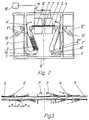
- the device shown after the two shrink dryers 9, 9 ', has two approximately U-shaped web store 1 and 2 for loosely accommodating one web section 3' and 3 "and one between these two web stores 1,2 arranged, connecting these and in its longitudinal direction on its two end faces delimited by a web impact surface 4 and 4 'each web guide and acceleration channel 5.
- This component 8 can also be omitted or, as in the illustrated embodiment, e.g. can be combined with two shrink dryers 9 and 9 'arranged on the inlet side, the latter also serving as a feed arrangement 9' for the continuous feed of the web 3 to be treated into the first web store 1.
- optical scanning means 10 and 10' are provided in the lower deflection areas of the two web stores 1 and 2 to determine the degree of filling of the two web stores 1 and 2 with sections 3 'and 3 "of the web to be treated 3 to scan.
- the pneumatic conveying means assigned to the acceleration channel 5 are like 3, divided into two pneumatic conveying means groups (blowing nozzles) 6 and 6 'acting in opposite directions of the acceleration channel 5. These two blow nozzle groups 6 and 6 'are connected to one another in alternating fashion, for example via a flip-flop switchover element 11 (see FIG. 2) which operates on the principle of the Coanda effect (see FIG. 2).
- the air used can have a temperature in the range of, for example, approximately 80 to 200 ° C.
- the two shrink driers 9 and 9 ' are for receiving and transporting the goods 3 to be treated through the shrink driers and for delivering the goods 3 emerging from the shrink dryer 9' into the first web store 1 provided with a common, continuously drivable, air-permeable, endlessly rotating conveyor belt 13, which with a conveying speed of about 40 to 50m / min. is driven.
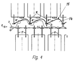
- An upper, stationary and air-permeable boundary wall 15 is arranged in the latter to form a transport channel 14 which is limited in the vertical direction at the top and bottom and serves to receive and support the goods 3 to be treated 3 and which is penetrated by blow nozzles 16 which are directed downwards and run transversely to the web conveying direction is.
- the upper, air-permeable perforated boundary wall 15 has at least approximately the shape of a shed roof in a vertical section running longitudinally to the web transport direction (see in particular FIG. 4), with between two mutually adjacent angular sections 15 ', 15 '', 15 '''etc. each facing downwards Blowing nozzle 16 is arranged, which are simultaneously designed to support the associated sections 15 ', 15'',15''' etc.
- the distance a between the upper blowing nozzles 16 and thus the upper boundary wall 15 supported on them is opposite the bearing surface b of the conveyor belt 13, e.g. adjustable in a range from about 10 to 80mm.
- two lower blowing nozzles 17, which support the upper run of the conveyor belt 13 and are directed upward into the associated angular sections 15 ′, 15 ′′, 15 ′′ ′′ etc. of the upper boundary wall 15, are provided between two upper blowing nozzles 16 .
- the lateral horizontal spacing of the upper blowing nozzles 16 is approximately 190 mm and that of the lower blowing nozzles 17 is approximately 95 mm.
- the upper and the lower, blowing air supplying blow nozzles 16 and 17 are each divided into groups and can be connected alternately and in a pulsating manner about 2 times per second via switching means 18 to a hot air source 19.
- the subdivision and switchover is designed such that each active blow nozzle group is opposed by an inactive blow nozzle group and the blow nozzle groups immediately adjacent to the side of an active blow nozzle group are inactive. In this way it is ensured that, alternately, a section of the goods 3 passing through a shrink dryer 9 or 9 'is always pressed down by upper blow nozzles 16 onto the bearing surface b of the endlessly rotating conveyor belt 13 and thus inevitably is conveyed together with this through the corresponding shrink dryer 9 or 9 '.
- the lattice-like and thus air-permeable design of the impact surface 4 makes it impossible to form an air cushion that dampens the impact between the impacting web section and the impact surface 4.
- the two pneumatic conveying means groups 6, 6 'on both sides of the acceleration channel 5 are mutually offset by the distance from one another by the angle y directed obliquely to the web transport plane, which means that the wave through the acceleration channel 5 against the impact surface 4 to be transported 3 in the area of the active blowing nozzle group 6 (FIG. 3 right), whereby the transport air in this area attacks the goods 3 to be transported extremely efficiently and a very good transport effect on it.
- saturated steam may also be expedient to supply saturated steam to the nozzle arrangement 6 and / or 6 'when they are used, in order to additionally achieve the passing goods 3 before they enter the second shrink dryer 9' in order to achieve an even stronger and more uniform shrinkage exposed to saturated steam treatment.
Landscapes
- Engineering & Computer Science (AREA)
- Textile Engineering (AREA)
- Mechanical Engineering (AREA)
- General Engineering & Computer Science (AREA)
- Treatment Of Fiber Materials (AREA)
- Drying Of Solid Materials (AREA)
Claims (21)
- Procédé pour le rétrécissement en continu de tissus, en particulier de tissus maillés, selon lequel la bande de tissu (3) à traiter est posée à l'état lâche sur une bande transporteuse sans fin (13) perméable à l'air, puis soumise dans un conduit de transport (14) à un brusque mouvement de va-et-vient, tout en étant séchée, à l'aide de buses soufflantes (16, 17) se faisant face par rapport à la bande de tissu (3) et dirigées vers la surface d'appui (b) de celle-ci, caractérisé en ce que les buses soufflantes se faisant face sont mises en marche et arrêtées en alternance, de façon groupée, et en ce que la bande de tissu est amenée, à l'aide des buses soufflantes (17) agissant à travers la bande transporteuse, contre une surface de compression de bande de tissu (15) qui délimite le conduit de transport et qui est perméable à l'air.
- Procédé selon la revendication 1, caractérisé en ce que la fréquence de commutation de groupes de buses soufflantes se faisant face se situe dans la plage de 1 à 6, de préférence de 1 à 3 commutations par seconde, et la vitesse d'avance de la bande de tissu se situe dans la plage de 10 à 80, de préférence de 30 à 50 m/s.
- Procédé selon l'une des revendications 1 ou 2, caractérisé en ce que, avant et/ou après les phases du procédé définies dans la revendication 1, on amène en continu la bande de tissu (3) à traiter dans un premier réservoir de bande de tissu (1) où on la stocke par sections, on l'extrait de ce premier réservoir par voie pneumatique et on la projette contre une première surface de collision (4) moyennant une compression, puis on amène le tissu (3) ainsi comprimé dans un second réservoir de bande de tissu (2) où on le stocke par sections, on effectue ensuite la même opération dans le sens de transport inverse à partir du second réservoir (2) vers une seconde surface de collision (4') puis vers le premier réservoir (1), mais avec une moins grande avance de longueur de bande de tissu, et on reproduit ces mouvements alternés, en évacuant en continu du second réservoir (2) la différence d'avance entre ces sections de longueur de bande de tissu soumises au mouvement de va-et-vient.
- Procédé selon la revendication 3, caractérisé en ce que le tissu (3) évacué du second réservoir de bande de tissu (2) est ensuite soumis au moins encore une fois au même procédé de traitement selon la revendication 3.
- Procédé selon la revendication 3 ou 4, caractérisé en ce qu'on projette la bande de tissu (3) à traiter contre la surface de collision correspondante (4, 4') avec une vitesse située dans la plage de 400 à 1000 m/min., de préférence avec une vitesse située dans la plage de 600 à 800 m/min.
- Procédé selon l'une des revendications 3 à 5, caractérisé en ce qu'on stocke provisoirement le tissu (3) à traiter, par sections, dans des réservoirs de bande de tissu (1, 2) au moins approximativement en U, étant précisé que le tissu (3) à traiter et à stocker provisoirement est introduit en continu dans la première branche (l') du premier réservoir en U (1), qu'il est extrait en continu, en alternance et par sections, de la seconde branche (1") puis ramené dans celle-ci dans le sens de transport inverse, ressorti et ainsi de suite, que le tissu (3) traité est introduit en continu, en alternance et par sections dans la première branche (2') du second réservoir de bande de tissu (2), qu'il en est extrait dans le sens de transport inverse et ramené dans cette branche (2') et ainsi de suite, et que le tissu (3) entièrement traité est extrait en continu de la seconde branche (2") du second réservoir en U (2).
- Procédé selon l'une des revendications 3 à 6, caractérisé en ce que le transport pneumatique de la bande de tissu (3) à traiter se fait entre les deux surfaces de collision (4, 4') à l'aide de buses soufflantes (fig. 3) disposées des deux côtés de la bande de tissu et décalées latéralement les unes par rapport aux autres, dirigées en biais par rapport au plan de transport de la bande de tissu et disposées juste avant les surfaces de collision à solliciter (4, 4').
- Procédé selon l'une des revendications 3 à 7, caractérisé en ce que les zones du tissu à traiter qui entrent pour la première fois dans le premier réservoir de bande de tissu présentent une humidité résiduelle maximum de 35 %, de préférence inférieure à 20 % mais d'au moins 6 %.
- Procédé selon l'une des revendications 3 à 8, caractérisé en ce qu'on soumet le tissu à traiter à un traitement à la vapeur saturée pendant son transport d'un réservoir de bande de tissu (1, 2) jusqu'à la surface de collision agissant en aval (4 ou 4').
- Dispositif pour la mise en oeuvre du procédé selon la revendication 1, comportant une bande transporteuse sans fin (13) apte à être entraînée en continu et perméable à l'air, et un conduit de transport (14) délimitant en haut et en bas le brin supérieur de la bande transporteuse, étant précisé que la bande transporteuse forme une surface d'appui (b) pour la bande de tissu et que des buses soufflantes (16, 17) se faisant face, décalées les unes par rapport aux autres et dirigées vers ladite surface d'appui de bande de tissu (b) sont disposées des deux côtés du conduit de transport, caractérisé en ce que la paroi de limitation supérieure du conduit de transport est conçue comme une surface de compression de bande de tissu (15) qui est perméable à l'air et traversée par des buses soufflantes (16) dirigées vers le bas, et qui a de préférence, vue en coupe verticale longitudinalement par rapport au sens de transport du tissu (fig. 4), au moins approximativement une forme ondulée ou une forme de toit à redents, de préférence la forme de sections de paroi successives (15, 15', 15", etc.) qui s'étendent transversalement par rapport au sens de passage, qui présentent une section transversale au moins approximativement angulaire et entre lesquelles sont disposées des buses soufflantes (16) dirigées vers le bas.
- Dispositif selon la revendication 10, caractérisé en ce que les buses soufflantes supérieures et inférieures (16, 17) sont groupées et reliées à une soufflante (19) par l'intermédiaire de moyens de commutation (18), le groupement et la commutation étant conçus de telle sorte qu'en face d'un groupe de buses soufflantes (16) actif se trouve un groupe de buses soufflantes (17) inactif et que le ou éventuellement les groupes de buses soufflantes voisins immédiats, latéralement, d'un groupe actif sont inactifs, et que la commutation des groupes de buses soufflantes se fait par impulsions entre l'état actif et l'état inactif.
- Dispositif selon l'une des revendications 10 ou 11, caractérisé en ce que l'écartement vertical (a) entre les orifices de sortie des buses soufflantes supérieures et inférieures (16, 17) est réglable de préférence dans une plage d'environ 10 à 80 mm.
- Dispositif selon l'une des revendications 10 à 12, caractérisé en ce que l'écartement latéral entre les buses soufflantes supérieures (16) se situe dans la plage de 140 à 220 mm et est de préférence au moins approximativement de 185 mm, tandis que l'écartement latéral entre les buses soufflantes inférieures (17) se situe dans la plage de 70 à 100 mm et est de préférence au moins approximativement de 95 mm.
- Dispositif selon la revendication 10 pour la mise en oeuvre du procédé selon la revendication 3, caractérisé en ce qu'il comporte deux réservoirs de bande de tissu (1, 2) destinés à recevoir de façon lâche des sections de tissu respectives, un conduit de guidage et d'accélération de bande de tissu (5) disposé entre ces deux réservoirs de bande de tissu (1, 2), reliant ceux-ci et délimité dans son sens longitudinal, sur ses deux faces frontales, par des surfaces de collision de bande de tissu respectives (4, 4'), des moyens convoyeurs pneumatiques (6, 6') reliés au conduit (5) et aptes à être mis en action de façon réversible dans les deux sens longitudinaux opposés dudit conduit pour le transport alterné d'une section du bande de tissu dans les sens longitudinaux opposés (7, 7') du conduit de guidage et d'accélération (5) vers la surface de collision de bande de tissu (4, 4') correspondante disposée côté frontal et, à partir de cette surface, vers le réservoir de bande de tissu (2, 1) correspondant, un dispositif d'amenée (3, 3') destiné à amener en continu la bande de tissu à traiter dans le premier réservoir de bande de tissu (1), et un dispositif d'évacuation (3, 3") destiné à évacuer en continu du second réservoir (2) la bande de tissu traitée.
- Dispositif selon la revendication 14, caractérisé en ce que les deux réservoirs de bande de tissu (1, 2) ont au moins approximativement la forme d'un U et contiennent de préférence des moyens de balayage optiques (10, 10') destinés à détecter par balayage leur degré de remplissage en sections partielles de la bande de tissu 3 à traiter, étant précisé que la première branche (1') du premier réservoir de bande de tissu en U (1) est conçue pour recevoir en continu, provisoirement et par sections le tissu (3) à traiter tandis que la seconde branche (1") est conçue pour extraire le tissu en continu, en alternance et par sections, pour le ramener dans le sens de transport inverse, pour l'extraire à nouveau et ainsi de suite, et que la première branche (2') du second réservoir de bande de tissu en U (2) est conçue pour recevoir le tissu en continu, en alternance et par sections, pour l'extraire en sens inverse, pour le recevoir à nouveau et ainsi de suite, tandis que la seconde branche (2") du second réservoir (2) est conçue pour l'extraction continue du tissu (3) traité.
- Dispositif selon la revendication 14 ou 15, caractérisé en ce que les moyens convoyeurs pneumatiques associés au conduit d'accélération (5) sont divisés en deux groupes (6, 6') agissant dans des sens opposés (7, 7') du conduit d'accélération (5), et ces deux groupes (6, 6') sont reliés séparément et en alternance à une source d'air comprimé (12), par l'intermédiaire d'un élément de commutation (11) fonctionnant de préférence suivant le principe de l'effet Coanda, étant précisé que ces deux groupes comportent, des deux côtés du conduit d'accélération (5), des buses soufflantes (6, 6') décalées mutuellement latéralement (X) et dirigées en biais par rapport au plan de transport de la bande de tissu, et qu'il sont disposés dans la zone d'extrémité dudit conduit d'accélération (5) si on considère leur sens de transport.
- Dispositif selon l'une des revendications 15 à 16, caractérisé en ce que les dispositifs d'amenée et d'évacuation (3', 3") sont conçus pour que leurs vitesses de transport soient réglables indépendamment l'une de l'autre.
- Dispositif selon l'une des revendications 14 à 17, caractérisé en ce que les surfaces de collision de bande de tissu (4, 4') présentent une structure de grille et ont une forme bombée vers l'extérieur et vers le bas pour recevoir en la comprimant une section de bande de tissu projetée contre elles.
- Dispositif selon la revendication 14, caractérisé en ce que plusieurs agencements selon la revendication 14 sont montés en série.
- Dispositif selon l'une des revendications 14 à 19, caractérisé en ce qu'au moins un séchoir de rétrécissement (9) est prévu en amont du premier réservoir de bande de tissu (1), et/ou au moins un séchoir de rétrécissement (9') est prévu en aval du dernier réservoir de bande de tissu (2).
- Utilisation du procédé selon la revendication 1 pour le traitement de peluches et de tissu éponge.
Applications Claiming Priority (2)
| Application Number | Priority Date | Filing Date | Title |
|---|---|---|---|
| CH2805/91 | 1991-09-21 | ||
| CH280591 | 1991-09-21 |
Publications (2)
| Publication Number | Publication Date |
|---|---|
| EP0535288A1 EP0535288A1 (fr) | 1993-04-07 |
| EP0535288B1 true EP0535288B1 (fr) | 1996-02-21 |
Family
ID=4241988
Family Applications (1)
| Application Number | Title | Priority Date | Filing Date |
|---|---|---|---|
| EP91810828A Expired - Lifetime EP0535288B1 (fr) | 1991-09-21 | 1991-10-28 | Procédé et installation de rétrécissement de tissus |
Country Status (6)
| Country | Link |
|---|---|
| US (1) | US5274892A (fr) |
| EP (1) | EP0535288B1 (fr) |
| JP (1) | JPH05302258A (fr) |
| AT (1) | ATE134397T1 (fr) |
| DE (1) | DE59107436D1 (fr) |
| ES (1) | ES2082957T3 (fr) |
Families Citing this family (18)
| Publication number | Priority date | Publication date | Assignee | Title |
|---|---|---|---|---|
| US5464685A (en) * | 1994-03-25 | 1995-11-07 | Asten, Inc. | Textile dryer apparatus having an improved textile dryer fabric |
| ES2120335B1 (es) * | 1995-09-07 | 1999-03-16 | Turbang Prototips Sl | Aparato para tratamiento en seco de un tejido. |
| US5795517A (en) * | 1996-05-03 | 1998-08-18 | Owens-Corning Canada | Collection and deposition of chopped fibrous strands for formation into non-woven webs of bonded chopped fibers |
| EP0806512B1 (fr) * | 1996-05-08 | 2001-08-08 | Solipat Ag | Procédé et dispositif de fibrillation de fibres cellulosiques facilement fibrillables, notamment de fibres tencel |
| US5893933A (en) * | 1996-05-23 | 1999-04-13 | Solipat Ag | Device and method for the continuous fulling of a material web of textile woven fabrics and knitted fabrics |
| AU4419297A (en) * | 1996-10-02 | 1998-04-24 | Milliken Research Corporation | Method and apparatus for web treatment |
| UA73147C2 (en) * | 1999-11-02 | 2005-06-15 | Apparatus for continuous and combined action for vibration-intensified dyeing with spraying at whole width of the fabric | |
| US20020176958A1 (en) * | 2000-04-06 | 2002-11-28 | Nord Thomas D. | Wiping cloth |
| DE10036058A1 (de) * | 2000-07-25 | 2002-02-21 | Monforts Textilmaschinen Gmbh | Relaxiertrockner |
| KR100384222B1 (ko) * | 2000-12-30 | 2003-05-16 | 김용근 | 원단가공장치 |
| EP1351030A1 (fr) * | 2002-04-02 | 2003-10-08 | Solipat Ag | Dispositif et procédé de consolidation d'un composite en fibres |
| US6811463B2 (en) * | 2002-06-21 | 2004-11-02 | Christine Martz | Air filled brassiere |
| DE102005034580B3 (de) * | 2005-07-25 | 2006-10-12 | A. Monforts Textilmaschinen Gmbh & Co. Kg | Vorrichtung zum Trocknen und Krumpfen einer Stoffbahn |
| US8061055B2 (en) * | 2007-05-07 | 2011-11-22 | Megtec Systems, Inc. | Step air foil web stabilizer |
| ITFI20080100A1 (it) * | 2008-05-19 | 2009-11-20 | Coramtex Srl | "macchina per la lavorazione di tessuti in largo e relativo metodo" |
| TR200804199A2 (tr) * | 2008-06-10 | 2009-12-21 | Entema Endüstri̇yel Tesi̇sler Ve Maki̇na Sanayi̇ Li̇mi̇ted Şi̇rketi̇ | Dokunmuş ve örülmüş kumaşlar için yumuşatma ve hacimleme makinası |
| WO2014047307A1 (fr) * | 2012-09-21 | 2014-03-27 | Eagle Ottawa, Llc | Procédé et système de ramollissement pour produits en rouleau |
| CN112378217A (zh) * | 2020-10-15 | 2021-02-19 | 湖州金玺丝绸科技股份有限公司 | 一种丝织品烘干装置 |
Family Cites Families (11)
| Publication number | Priority date | Publication date | Assignee | Title |
|---|---|---|---|---|
| DE2313948A1 (de) * | 1973-03-21 | 1974-09-26 | Artos Meier Windhorst Kg | Verfahren und vorrichtung zum behandeln, insbesondere schrumpfen von warenbahnen |
| DE2918833C2 (de) * | 1979-05-10 | 1985-11-21 | Dipl.-Ing. Gerhard Ruckh, Maschinenfabrik, 7320 Göppingen | Vorrichtung zum Trocknen und Krumpfen von textiler Maschenware |
| US4409709A (en) * | 1979-05-16 | 1983-10-18 | Sando Iron Works Co., Ltd. | Apparatus for continuous untwisting and crimping of a cloth |
| DE2951295A1 (de) * | 1979-12-20 | 1981-06-25 | Vepa AG, 4125 Riehen, Basel | Vorrichtung zum waermebehandeln von ausgebreiteten textilguetern, insbesondere zum relaxieren |
| DE3025154A1 (de) * | 1980-07-03 | 1982-01-28 | Brückner-Apparatebau GmbH, 6120 Erbach | Verfahren und vorrichtung zur breithaltung einer bewegten textilen warenbahn |
| DE3365330D1 (en) * | 1983-10-08 | 1986-09-18 | Mtm Obermaier Gmbh & Co Kg | Apparatus for the continuous and tensionless treatment of textile webs |
| US4679333A (en) * | 1985-11-08 | 1987-07-14 | Vinas Jaime A | Apparatus for the dry treatment of a fabric |
| DE8713616U1 (de) * | 1987-10-10 | 1989-02-02 | Hergeth Hollingsworth GmbH, 4408 Dülmen | Kastenspeiser zur Herstellung einer Mischung aus Fasergut, insbesondere Textilfasergut |
| US4974341A (en) * | 1988-05-06 | 1990-12-04 | Jaume Anglada Vinas S.A. | Apparatus for dry treatment of a fabric |
| US4942676A (en) * | 1988-06-07 | 1990-07-24 | W. R. Grace & Co.-Conn. | Control system for air flotation dryer with a built-in afterburner |
| US5014525A (en) * | 1989-10-24 | 1991-05-14 | Madinox S.A. | Machine for dyeing fabric in a rope |
-
1991
- 1991-10-28 DE DE59107436T patent/DE59107436D1/de not_active Expired - Fee Related
- 1991-10-28 ES ES91810828T patent/ES2082957T3/es not_active Expired - Lifetime
- 1991-10-28 AT AT91810828T patent/ATE134397T1/de not_active IP Right Cessation
- 1991-10-28 EP EP91810828A patent/EP0535288B1/fr not_active Expired - Lifetime
-
1992
- 1992-09-21 US US07/947,586 patent/US5274892A/en not_active Expired - Fee Related
- 1992-09-21 JP JP4294711A patent/JPH05302258A/ja active Pending
Also Published As
| Publication number | Publication date |
|---|---|
| ATE134397T1 (de) | 1996-03-15 |
| US5274892A (en) | 1994-01-04 |
| EP0535288A1 (fr) | 1993-04-07 |
| DE59107436D1 (de) | 1996-03-28 |
| ES2082957T3 (es) | 1996-04-01 |
| JPH05302258A (ja) | 1993-11-16 |
Similar Documents
| Publication | Publication Date | Title |
|---|---|---|
| EP0535288B1 (fr) | Procédé et installation de rétrécissement de tissus | |
| EP0725178B1 (fr) | Procédé et dispositif de séchage et de rétrécissement d'étoffe textile | |
| EP0818568B1 (fr) | Procédé et dispositif pour l'entrelacement hydrodynamique de fibres d'une nappe fibreuse | |
| DE2644309C2 (de) | Verfahren und Vorrichtung zum Behandeln von textilen Warenbahnen | |
| EP0535287B1 (fr) | Procédé et installation pour l'amélioration du toucher et de l'état de surface de tissus et tricots | |
| DE3036669C2 (fr) | ||
| DE602005006290T2 (de) | Maschine und verfahren zur behandlung von sowohl breitmaschigem als auch strangförmigem stoff | |
| DE1944350A1 (de) | Verfahren und Vorrichtung zum kontinuierlichen Entspannen von Textilerzeugnissen | |
| EP0358136B1 (fr) | Procédé et dispositif de traitement des bandes continues textiles | |
| EP1530699B1 (fr) | Dispositif d'appret de tissu | |
| EP0148113B1 (fr) | Procédé de séchage et de rétrécissement de tissus textiles et installation à cet effet | |
| DE2918833C2 (de) | Vorrichtung zum Trocknen und Krumpfen von textiler Maschenware | |
| DE2942030A1 (de) | Maschine zum trocknen von geweben, insbesondere von strickgeweben der sogenannten jersey-art | |
| EP0808930A1 (fr) | Dispositif et procédé de foulage à la continue de tissus et tricots textiles | |
| DE2319464A1 (de) | Verfahren und vorrichtung zur behandlung von guetern, insbesondere zur trocknung feuchter gueter | |
| DE69616503T2 (de) | Vorrichtung zur Trockenbehandlung eines Gewebes | |
| DE102005034579A1 (de) | Vorrichtung zum Trocknen und Krumpfen einer Stoffbahn | |
| EP0519173B1 (fr) | Procédé pour le conditionnement en continu, notamment pour le conditionnement thermique de matière particulaire, de préférence matière particulaire végétale comme les céréales, les herbes, le tabac ou analogues | |
| DE2336518B2 (de) | Vorrichtung zum behandeln von webketten | |
| EP0669416A1 (fr) | Procédé et dispositif pour le traitement d'une bande textile particulièrement sensible à l'étirement | |
| EP0107002B1 (fr) | Procédé et appareil pour rendre irrétrécissable une matière textile tubulaire | |
| CH686588A5 (de) | Vorrichtung zum Beblasen einer textilen Warenbahn. | |
| AT508471B1 (de) | Vorrichtung zur herstellung einer faserstoffbahn | |
| DE10036058A1 (de) | Relaxiertrockner | |
| AT408670B (de) | Verfahren und vorrichtung zum kontinuierlichen trocknen und krumpfen von textiler maschen- oder webware |
Legal Events
| Date | Code | Title | Description |
|---|---|---|---|
| PUAI | Public reference made under article 153(3) epc to a published international application that has entered the european phase |
Free format text: ORIGINAL CODE: 0009012 |
|
| AK | Designated contracting states |
Kind code of ref document: A1 Designated state(s): AT CH DE ES FR GB IT LI SE |
|
| 17P | Request for examination filed |
Effective date: 19930608 |
|
| 17Q | First examination report despatched |
Effective date: 19941020 |
|
| GRAA | (expected) grant |
Free format text: ORIGINAL CODE: 0009210 |
|
| AK | Designated contracting states |
Kind code of ref document: B1 Designated state(s): AT CH DE ES FR GB IT LI SE |
|
| REF | Corresponds to: |
Ref document number: 134397 Country of ref document: AT Date of ref document: 19960315 Kind code of ref document: T |
|
| REF | Corresponds to: |
Ref document number: 59107436 Country of ref document: DE Date of ref document: 19960328 |
|
| REG | Reference to a national code |
Ref country code: CH Ref legal event code: NV Representative=s name: HEPP, WENGER & RYFFEL AG |
|
| REG | Reference to a national code |
Ref country code: ES Ref legal event code: FG2A Ref document number: 2082957 Country of ref document: ES Kind code of ref document: T3 |
|
| ET | Fr: translation filed | ||
| ITF | It: translation for a ep patent filed | ||
| GBT | Gb: translation of ep patent filed (gb section 77(6)(a)/1977) |
Effective date: 19960513 |
|
| PLBE | No opposition filed within time limit |
Free format text: ORIGINAL CODE: 0009261 |
|
| STAA | Information on the status of an ep patent application or granted ep patent |
Free format text: STATUS: NO OPPOSITION FILED WITHIN TIME LIMIT |
|
| 26N | No opposition filed | ||
| PGFP | Annual fee paid to national office [announced via postgrant information from national office to epo] |
Ref country code: SE Payment date: 19970924 Year of fee payment: 7 |
|
| PGFP | Annual fee paid to national office [announced via postgrant information from national office to epo] |
Ref country code: AT Payment date: 19970929 Year of fee payment: 7 |
|
| PGFP | Annual fee paid to national office [announced via postgrant information from national office to epo] |
Ref country code: ES Payment date: 19971010 Year of fee payment: 7 |
|
| PGFP | Annual fee paid to national office [announced via postgrant information from national office to epo] |
Ref country code: GB Payment date: 19971015 Year of fee payment: 7 |
|
| PGFP | Annual fee paid to national office [announced via postgrant information from national office to epo] |
Ref country code: FR Payment date: 19971029 Year of fee payment: 7 |
|
| PGFP | Annual fee paid to national office [announced via postgrant information from national office to epo] |
Ref country code: DE Payment date: 19971216 Year of fee payment: 7 |
|
| PGFP | Annual fee paid to national office [announced via postgrant information from national office to epo] |
Ref country code: CH Payment date: 19980112 Year of fee payment: 7 |
|
| PG25 | Lapsed in a contracting state [announced via postgrant information from national office to epo] |
Ref country code: GB Free format text: LAPSE BECAUSE OF NON-PAYMENT OF DUE FEES Effective date: 19981028 Ref country code: AT Free format text: LAPSE BECAUSE OF NON-PAYMENT OF DUE FEES Effective date: 19981028 |
|
| PG25 | Lapsed in a contracting state [announced via postgrant information from national office to epo] |
Ref country code: SE Free format text: LAPSE BECAUSE OF NON-PAYMENT OF DUE FEES Effective date: 19981029 Ref country code: ES Free format text: LAPSE BECAUSE OF NON-PAYMENT OF DUE FEES Effective date: 19981029 |
|
| PG25 | Lapsed in a contracting state [announced via postgrant information from national office to epo] |
Ref country code: LI Free format text: LAPSE BECAUSE OF NON-PAYMENT OF DUE FEES Effective date: 19981031 Ref country code: CH Free format text: LAPSE BECAUSE OF NON-PAYMENT OF DUE FEES Effective date: 19981031 |
|
| REG | Reference to a national code |
Ref country code: CH Ref legal event code: PL |
|
| GBPC | Gb: european patent ceased through non-payment of renewal fee |
Effective date: 19981028 |
|
| EUG | Se: european patent has lapsed |
Ref document number: 91810828.3 |
|
| PG25 | Lapsed in a contracting state [announced via postgrant information from national office to epo] |
Ref country code: FR Free format text: LAPSE BECAUSE OF NON-PAYMENT OF DUE FEES Effective date: 19990630 |
|
| REG | Reference to a national code |
Ref country code: FR Ref legal event code: ST |
|
| PG25 | Lapsed in a contracting state [announced via postgrant information from national office to epo] |
Ref country code: DE Free format text: LAPSE BECAUSE OF NON-PAYMENT OF DUE FEES Effective date: 19990803 |
|
| REG | Reference to a national code |
Ref country code: ES Ref legal event code: FD2A Effective date: 19991113 |
|
| PG25 | Lapsed in a contracting state [announced via postgrant information from national office to epo] |
Ref country code: IT Free format text: LAPSE BECAUSE OF NON-PAYMENT OF DUE FEES;WARNING: LAPSES OF ITALIAN PATENTS WITH EFFECTIVE DATE BEFORE 2007 MAY HAVE OCCURRED AT ANY TIME BEFORE 2007. THE CORRECT EFFECTIVE DATE MAY BE DIFFERENT FROM THE ONE RECORDED. Effective date: 20051028 |