EP1351030A1 - Dispositif et procédé de consolidation d'un composite en fibres - Google Patents
Dispositif et procédé de consolidation d'un composite en fibres Download PDFInfo
- Publication number
- EP1351030A1 EP1351030A1 EP02405255A EP02405255A EP1351030A1 EP 1351030 A1 EP1351030 A1 EP 1351030A1 EP 02405255 A EP02405255 A EP 02405255A EP 02405255 A EP02405255 A EP 02405255A EP 1351030 A1 EP1351030 A1 EP 1351030A1
- Authority
- EP
- European Patent Office
- Prior art keywords
- fiber composite
- blowing
- blowing nozzles
- treatment medium
- nozzles
- Prior art date
- Legal status (The legal status is an assumption and is not a legal conclusion. Google has not performed a legal analysis and makes no representation as to the accuracy of the status listed.)
- Withdrawn
Links
Images



Classifications
-
- F—MECHANICAL ENGINEERING; LIGHTING; HEATING; WEAPONS; BLASTING
- F26—DRYING
- F26B—DRYING SOLID MATERIALS OR OBJECTS BY REMOVING LIQUID THEREFROM
- F26B13/00—Machines and apparatus for drying fabrics, fibres, yarns, or other materials in long lengths, with progressive movement
- F26B13/10—Arrangements for feeding, heating or supporting materials; Controlling movement, tension or position of materials
- F26B13/101—Supporting materials without tension, e.g. on or between foraminous belts
-
- F—MECHANICAL ENGINEERING; LIGHTING; HEATING; WEAPONS; BLASTING
- F26—DRYING
- F26B—DRYING SOLID MATERIALS OR OBJECTS BY REMOVING LIQUID THEREFROM
- F26B17/00—Machines or apparatus for drying materials in loose, plastic, or fluidised form, e.g. granules, staple fibres, with progressive movement
- F26B17/02—Machines or apparatus for drying materials in loose, plastic, or fluidised form, e.g. granules, staple fibres, with progressive movement with movement performed by belts carrying the materials; with movement performed by belts propelling the materials over stationary surfaces
- F26B17/026—Machines or apparatus for drying materials in loose, plastic, or fluidised form, e.g. granules, staple fibres, with progressive movement with movement performed by belts carrying the materials; with movement performed by belts propelling the materials over stationary surfaces the material being moved in-between belts which may be perforated
Definitions
- the invention relates to a device and method for solidifying a fiber composite with the features of the generic term of the independent claims.
- Such a fiber composite is often referred to as a nonwoven.
- the fiber composite consists of a mixture of basic fibers, for example cotton fibers or flax fibers and from Binding fibers, for example meltable plastic fibers. binder fibers can be melted by heating. Thereby the loose fiber composite can be consolidated. To solidify It is known from such fiber composites that the fiber composite is continuous along a conveyor path in a dryer device to promote and thereby apply heat. Subsequently the fiber composite is cooled.
- Non-woven mat can be used, for example, as upholstery, insulating material, Mattresses or used as a cosmetic product (cotton wool) become.
- suction dryers air is in one Drying device in a direction transverse to the conveying direction sucked through the fiber composite. In such dryers satisfactory heat exposure to the fiber composite can be achieved across its entire thickness.
- Such devices but have certain disadvantages.
- To perform this procedure must be on one side of the fiber composite being conveyed a negative pressure can be generated. Heated air is on the suctioned opposite side from a chamber. Is to this chamber is provided with openings, for example slits, which run transversely to the conveying direction of the fiber composite. In order to it is ensured that the air through the fiber composite is sucked through, it is necessary to adjust the width of this Adjust openings to the width of the respective fiber composite.
- Another type of such device is the device trained as a blow dryer.
- a blow dryer Such a device is e.g. known from DE 30 23 229.
- heated air is removed Blowing nozzles blown against the fiber composite.
- blow dryers are combined with relatively thin fibers can be used satisfactorily.
- the fiber composite is from one side blown hot air enters the fiber composite, but is reflected to some extent by this and again on the same side emerges from the fiber composite.
- Treatment of thicker fiber composites therefore results in one middle area a zone which is not sufficient with Heat is applied and in which the binding fibers are not be melted sufficiently.
- the fiber composite is therefore not solidified evenly over its entire thickness.
- the device for strengthening the fiber composite Fiber composite continuously conveyed along a conveyor path.
- the consolidation takes place by loading the fiber composite with warmth.
- the device has at least one nozzle arrangement on.
- the at least one nozzle arrangement is on at least one Arranged side of the conveyor path.
- the nozzle arrangement is used for Blowing a heated treatment medium in the direction of the conveying path against the fiber composite.
- a treatment medium typically uses air. But it would also be other treatment media conceivable.
- the at least one nozzle arrangement has a plurality of adjacent blowing nozzles, i.e. the device is designed as a blow dryer.
- the blow nozzles are spaced apart in a known manner, so that there is a space between each two adjacent blowing nozzles is formed.
- the space between the blowing nozzles essentially closed towards the conveying path or lockable training. This ensures that the treatment medium is forced by the to pass through the entire thickness of the fiber composite. In this way uniform consolidation of the fiber composite guaranteed its entire thickness.
- the gap it is not necessary close the gap completely airtight. It is sufficient to close the gap in such a way that between a pressure chamber is formed of the nozzle arrangement and the fiber composite is created in which an excess pressure is generated by means of the blowing nozzles can be.
- the overpressure should be sufficiently large so that the treatment medium is forced through the entire fiber composite to pass through.
- the invention exists So in it, a device for solidifying a continuously conveyed fiber composite so that a treatment medium even with a relatively thick fiber composite, typically more than 5 to 10 cm thick, through the entire thickness of the fiber composite can be blown through. If the device is used to make relatively thin fiber composites it is also conceivable to solidify the spaces between to open the blow nozzles.
- the gap is therefore locked or closable in such a way that with a given fiber composite (especially given material, given density and given thickness) and with given Exit velocity and exit quantity of the treatment medium the treatment medium from the blow nozzles entire thickness of the fiber composite is blowable.
- the blowing nozzles advantageously have a blowing opening which ends adjacent to the surface of the fiber composite.
- the treatment medium can be blown directly into the fiber composite.
- a rotating upper or lower belt between which the fiber composite is conveyed is used to convey the fiber composite in such a device.
- the upper band or lower band is permeable to the treatment medium.
- the aim is to arrange the blowing opening as close as possible to the upper belt or lower belt.
- the distance between the surface of the fiber composite and the blowing opening of the blowing nozzles can be set according to a further preferred embodiment.
- sealing elements which in the space can be used between the blow nozzles.
- Sealing elements sheets are used, which are between the blowing nozzles can be inserted.
- the blowing nozzles are preferably designed as wide slot nozzles.
- the slot die extends essentially over the full width of the conveyor path in the device.
- the blow nozzles are advantageously provided with a nozzle box that has a cross section has that of a connection opening from which the treatment medium can be blown into the nozzle box into one closed end of the nozzle box decreases. With this in Area of dryer known measure is ensured that the exit velocity or the exit quantity of the treatment medium over the entire width of the conveying path or the fiber composite transverse to the conveying direction essentially remains constant.
- the blowing speed or the blowing quantity the treatment medium is independent of the width of the fiber composite to be treated. Because the flow resistance generated by the slot die has the width of the fiber composite no influence on the exit behavior of the treatment medium from the blow nozzle.
- Nozzle arrangements are arranged on both sides of the conveying path.
- the device can operate according to the invention as a blow dryer, with which treatment medium through the entire width of the fiber composite can be blown, it makes sense to blow the nozzles alternating on one side and on the other side of the funding path to arrange.
- blowing nozzles it is also conceivable to use blowing nozzles to be arranged simultaneously on both sides of the conveyor path, in each case but only the blow nozzles on one or the other Activate page.
- blow nozzles grouped together.
- the groups of Blow nozzles can be activated or deactivated individually.
- the gap between deactivated blowing nozzles is in this Context openable or open. This ensures that treatment medium emerging from the fiber composite can flow and that not on the opposite of the blow nozzles Side can build up a counter pressure.
- the device according to the invention is provided with at least one fan and with at least one heating device for heating the treatment medium.
- the fan and the heating device are designed such that 500 to 2000 m 3 of air per hour and per meter of working width at a temperature of 0 to 300 ° C. and at a speed of 0.5 to 70 m / s are preferred per blowing nozzle 20 to 40m / s is blowable against the fiber composite.
- the method according to the invention serves to solidify a fiber composite by applying heat.
- the fiber composite is continuously funded along a funding path.
- Overpressure is thus generated in the pressure chamber.
- the treatment medium is blown through the entire thickness of the fiber composite.
- the treatment medium directly from a blow opening of the blow nozzles, which the fiber composite lies adjacent to the surface of the fiber composite blown.
- the Distance between the blow opening of the blow nozzle and the surface of the fiber composite before the start of the fastening process a predeterminable value is set.
- the treatment medium viewed in the conveying direction, is blown alternately from one side and from the other side towards the fiber composite.
- groups of blowing nozzles are alternately activated and deactivated on one side of the fiber composite, and that the space between deactivated blowing nozzles is opened to enable the treatment medium to flow away.
- the treatment medium is typically blown out of the blow nozzles at a temperature of 0 to 300 ° C. and at an exit speed of 0.5 to 70 m per second. Typically, 500 to 2000 m 3 of air are blown out per hour per blowing nozzle and per meter of working width.
- Both the speed and the amount of blown out Treatment medium is significantly above the speed or over the discharge amount of the treatment medium, which at Suction dryers are sucked through the fiber composite.
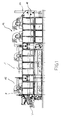
- Figure 1 shows a side view of a device according to the invention 1.
- the device 1 according to the invention is used for conveying of a fiber composite V along a conveying path F.
- a conveying path F For conveying of the fiber composite V through the device 1 is an upper band 17 and a lower band 18 are provided.
- the upper and lower band 17, 18 are designed as all-round, open-mesh bands, which are guided around pulleys in the device 1.
- the fiber composite V is between the upper belt 17 and the Lower band 18 promoted.
- the fiber composite V is typically a mixture of natural fibers, for example cotton or Flax fibers and from a binding fiber, for example one fusible plastic fiber used.
- the fiber composite V For strengthening the fiber composite V becomes the fiber composite in the device 1 in one Heating section 15 is subjected to heat, so that the binding fibers melt and the fiber composite V is solidified. Subsequently becomes the consolidated fiber composite V in a cooling section 16 cooled.
- the device 1 is designed as a dryer, the well-known way with fans, heating device and air vents.
- Air used at a temperature of 0 is heated to 300 ° C. This allows the inside of the fiber composite V can reach temperatures of up to 250 ° C.
- the device 1 is designed as a blow dryer. To this Purpose are on both sides 3a, 3b (see Figures 2 and 3) nozzle arrangements 2a, 2b to apply the fiber composite V. Heat W provided.
- Figure 2 shows a section of the device 1 in cross section in a side view.
- the fiber composite V is along of the conveying path F is conveyed in the conveying direction R by the device 1.
- the upper belt 17 serves to convey the fiber composite V. or the lower belt 18, wherein only the upper part of the Device 1 and correspondingly shown only the upper band 17 is.
- the nozzle arrangement 2a on the top of the fiber composite V has blowing nozzles 4.
- the blowing nozzles 4 blow heated air L in the direction of the fiber composite V via a blowing opening 7.
- the air L heated to 300 ° C. is blown out of the blowing openings 7 at a speed v of approximately 40 m / s. Up to 2000 m 3 of heated air L is blown out per hour per blowing nozzle 4.
- the blowing nozzles 4 are arranged at a distance a from one another, so that an intermediate space 5 is formed between adjacent blowing nozzles 4 becomes.
- the intermediate space 5 is between active ones Blow nozzles 4 closed by a sealing element 8.
- the sealing element 8 is a sheet formed, which bridges the gap 5.
- a pressure chamber 6 is formed, in which can generate an excess pressure P with the blowing nozzles 4.
- the blow opening 7 of the blow nozzles 4 is relatively close to the surface O of the fiber composite V arranged. It is also conceivable to design the distance b adjustable.
- FIG. 3 shows a larger section from the one according to the invention Device shown in side view.
- Figure 3 shows a first side 3a arranged above the fiber composite V.
- the Blow nozzles 4 are each grouped together. there are alternately on the top 3a and on the bottom 3b of the fiber composite V groups 12 activated by blowing nozzles 4. At the same time are alternately on the bottom 3b of the fiber composite V and on the top 2a of the fiber composite V groups 12 'of blowing nozzles 4' inactive. Based on the fiber composite V are therefore each inactive compared to active blow nozzles 4 Blow nozzles 4 '.
- the gap 5 is between inactive Blow nozzles 4 'open so that the active blow nozzles 4 through the fiber composite blown air L between the inactive blowing nozzles 4 'can flow.
- the treatment medium is alternated from the top to the top led below and from bottom to top through the fiber composite V.
- blow nozzles 4 'omitted it is also conceivable to use the inactive blow nozzles 4 'omitted.
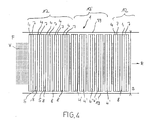
- FIG. 4 shows a top view of the device 1 promoted fiber composite V.
- the blowing nozzles 4 are as wide slot nozzles formed and each have a blow opening 7, which are essentially over the entire width B of the conveyor path F extends.
- the conveyor path F is defined by two lateral boundaries 19 indicated.
- a first group 12 of active blowing nozzles 4 is shown. It is followed by a group 12 'of inactive blow nozzles 4'.
- the between active Blow nozzles 4 formed space 5 is through the cover plate 8 closed, while the gap 5 between inactive blow nozzles 4 'remains open, so that from opposite Air blown between the inactive air nozzles 4 'can flow.
- Figure 5 shows schematically a cross section of the inventive Device seen in the conveying direction R.
- the fiber composite V is by means of the upper band 17 and the upper band 18 through the device 1 led.
- the nozzle arrangements 2a, 2b on both sides 3a, 3b of the fiber composite V consist of blowing nozzles 4, the are provided with a nozzle box.
- blowing nozzles 4 are provided with one blow opening 7 per nozzle box 9 (see Figure 5a).
- the nozzle box 9 has a connection opening 10 into which heated air L can be blown in by means of a fan 13 can.
- the cross section Q of the nozzle box 9 takes against a closed End 11 of the nozzle box 9 continuously. On in this way a uniform escape of the air L in the total width of the nozzle box 9 achieved.
- the heater 14 between fan 13 and connection opening 10 of the nozzle box 9 is used to heat the air L.
- the fan 13 is in known as a radial fan.
- the heater 14 and a fan 13 can be used to for example a group 12 (see FIGS. 3 and 4) of blowing nozzles 4 together with heated air L.
- a pivotable flap 20 is provided to either on the upper side 3a or on the lower side 3b of the fiber composite V arranged to activate bubble nozzles 4 or to deactivate.
- the flap closes 20 the connection opening 10 'of the lower nozzle box 9 during the connection opening 10 of the upper nozzle box is open.
- the connection opening 10 of the upper nozzle box 9 In the position shown in broken lines in FIG. 5 closes the position Flap 20, the connection opening 10 of the upper nozzle box 9 and thus activates the on the lower side 3b of the fiber composite V arranged nozzle boxes 9, so that blown from below to the top becomes.
- FIG. 6 shows the blow openings 7 in an enlarged representation of two adjacent blowing nozzles 4.
- the blowing openings 7 have a width c of 3mm to approx. 30 (with a working width dependent Length of the wide slot nozzles from 0.5 to several Meters).
- the blowing openings 7 are bent sheets trained, which the air against the surface O (see Figures 2 and 3) of the fiber composite V. Between the adjacent blowing openings 7, the space 5 is through an insertion plate 8 closed.
- the insertion plate 8 is as folded sheet formed.
- the sheet 8 has one on both sides H-shaped cross-section, by means of which the sheet over a U-shaped bend 21 can be pushed on at the end of the blowing opening 7 is.
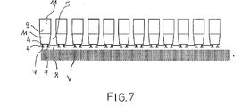
- Figure 7 shows a side view of several nozzle boxes 9 each two blowing openings 7.
- the nozzle boxes 9 are only on the upper Side 3a of the fiber composite V arranged.
- Corresponding blow nozzles can also be provided on the lower side 3b.
Landscapes
- Engineering & Computer Science (AREA)
- Mechanical Engineering (AREA)
- General Engineering & Computer Science (AREA)
- Textile Engineering (AREA)
- Treatment Of Fiber Materials (AREA)
- Spinning Methods And Devices For Manufacturing Artificial Fibers (AREA)
Priority Applications (8)
| Application Number | Priority Date | Filing Date | Title |
|---|---|---|---|
| EP02405255A EP1351030A1 (fr) | 2002-04-02 | 2002-04-02 | Dispositif et procédé de consolidation d'un composite en fibres |
| CNB038127237A CN100557356C (zh) | 2002-04-02 | 2003-03-28 | 用于强化纤维粘合非织造织物的装置和方法 |
| EP03708272A EP1490641A1 (fr) | 2002-04-02 | 2003-03-28 | Dispositif et procede de consolidation d'un composite fibre |
| CA002480805A CA2480805A1 (fr) | 2002-04-02 | 2003-03-28 | Dispositif et procede de consolidation d'un composite fibre |
| BR0308986-0A BR0308986A (pt) | 2002-04-02 | 2003-03-28 | Dispositivo e método para consolidar um composto de fibra |
| US10/509,731 US7032323B2 (en) | 2002-04-02 | 2003-03-28 | Device and method for compacting a fiber composite |
| AU2003212382A AU2003212382A1 (en) | 2002-04-02 | 2003-03-28 | Device and method for compacting a fiber composite |
| PCT/EP2003/003218 WO2003083394A1 (fr) | 2002-04-02 | 2003-03-28 | Dispositif et procede de consolidation d'un composite fibre |
Applications Claiming Priority (1)
| Application Number | Priority Date | Filing Date | Title |
|---|---|---|---|
| EP02405255A EP1351030A1 (fr) | 2002-04-02 | 2002-04-02 | Dispositif et procédé de consolidation d'un composite en fibres |
Publications (1)
| Publication Number | Publication Date |
|---|---|
| EP1351030A1 true EP1351030A1 (fr) | 2003-10-08 |
Family
ID=27838206
Family Applications (2)
| Application Number | Title | Priority Date | Filing Date |
|---|---|---|---|
| EP02405255A Withdrawn EP1351030A1 (fr) | 2002-04-02 | 2002-04-02 | Dispositif et procédé de consolidation d'un composite en fibres |
| EP03708272A Withdrawn EP1490641A1 (fr) | 2002-04-02 | 2003-03-28 | Dispositif et procede de consolidation d'un composite fibre |
Family Applications After (1)
| Application Number | Title | Priority Date | Filing Date |
|---|---|---|---|
| EP03708272A Withdrawn EP1490641A1 (fr) | 2002-04-02 | 2003-03-28 | Dispositif et procede de consolidation d'un composite fibre |
Country Status (7)
| Country | Link |
|---|---|
| US (1) | US7032323B2 (fr) |
| EP (2) | EP1351030A1 (fr) |
| CN (1) | CN100557356C (fr) |
| AU (1) | AU2003212382A1 (fr) |
| BR (1) | BR0308986A (fr) |
| CA (1) | CA2480805A1 (fr) |
| WO (1) | WO2003083394A1 (fr) |
Families Citing this family (2)
| Publication number | Priority date | Publication date | Assignee | Title |
|---|---|---|---|---|
| FR3037640B1 (fr) | 2015-06-19 | 2017-06-16 | Saint Gobain Isover | Etuve de reticulation d'un matelas continu de fibres minerales ou vegetales |
| US11578918B2 (en) * | 2016-11-09 | 2023-02-14 | Airffect Gmbh | Handheld blower device |
Citations (9)
| Publication number | Priority date | Publication date | Assignee | Title |
|---|---|---|---|---|
| GB744043A (en) * | 1950-11-15 | 1956-02-01 | Algemeene Kunstvezel Mij Naaml | Process and apparatus for the manufacture of heat and sound insulating sheet material of bonded glass fibres |
| FR2225706A1 (en) * | 1973-04-12 | 1974-11-08 | Dornier Gmbh Lindauer | Hot air dryer for continuous textile webs - uses hot air nozzles and evacuation ducts which are adjustable to maintain an air film between the web and nozzles |
| US4069595A (en) * | 1975-01-24 | 1978-01-24 | Aktiebolaget Svenska Flaktfabriken | Arrangement for conveying web material through a treating plant |
| EP0000111A1 (fr) * | 1977-06-09 | 1978-12-20 | Saint-Gobain Industries | Appareil pour le traitement thermique d'un matelas de fibres portant un liant thermoducissable |
| US4467537A (en) * | 1979-09-01 | 1984-08-28 | Lindauer Dornier Gesellschaft Mbh. | Equipment for heat-treating flat, band-like lengths of material |
| US4848633A (en) * | 1986-02-28 | 1989-07-18 | Thermo Electron Web Systems, Inc. | Non-contact web turning and drying apparatus |
| EP0619465A1 (fr) * | 1993-03-22 | 1994-10-12 | Sanei-Kisetsu Co., Ltd. | Procédé et dispositif de fabrication d'un tapis pour la construction |
| US5564200A (en) * | 1993-10-15 | 1996-10-15 | Solipat Ag | Device for heat treatment of a continuously guided material web, in particular a textile web |
| DE29900646U1 (de) * | 1999-01-18 | 1999-05-12 | Meissner, Wolfgang, 74595 Langenburg | Vorrichtung zur Vliesverfestigung mit Heißluft |
Family Cites Families (9)
| Publication number | Priority date | Publication date | Assignee | Title |
|---|---|---|---|---|
| DE3023225A1 (de) | 1980-06-21 | 1982-08-19 | GHTW-Wärmebehandlungsanlagen GmbH i.L., 7024 Filderstadt | Vorrichtung zur waermebehandlung einer warenbahn |
| DD210739A1 (de) | 1982-10-12 | 1984-06-20 | Dieter Glaeser | Duesenanordnung zur waermebehandlung von warenbahnen, insbesondere textilbahnen |
| EP0535288B1 (fr) * | 1991-09-21 | 1996-02-21 | Solipat Ag | Procédé et installation de rétrécissement de tissus |
| DE19525545C1 (de) * | 1995-07-13 | 1996-09-26 | Babcock Textilmasch | Trockner für durchlaufende Textilbahnen |
| DE19622000A1 (de) | 1996-05-31 | 1997-12-04 | Brueckner Trockentechnik Gmbh | Trocken- und/oder Fixiervorrichtung |
| DE19713529A1 (de) * | 1997-04-01 | 1998-10-08 | Heidelberger Druckmasch Ag | Trockner für eine Materialbahn mit Abgasezirkulation |
| DE19804396A1 (de) | 1998-02-04 | 1999-08-05 | Brueckner Apparatebau Gmbh | Vorrichtung zur Wärmebehandlung einer Warenbahn |
| US6131308A (en) * | 1999-09-10 | 2000-10-17 | Ingenieurgemeinschaft Wsp, Prof. Dr.-Ing C Kramer, Prof. Dipl.-Ing H.J. Gerhardt M.S. | Apparatus for levitational guidance of web material |
| DE10020387C1 (de) * | 2000-04-26 | 2001-03-08 | Monforts Textilmaschinen Gmbh | Relaxier-Trockner |
-
2002
- 2002-04-02 EP EP02405255A patent/EP1351030A1/fr not_active Withdrawn
-
2003
- 2003-03-28 CN CNB038127237A patent/CN100557356C/zh not_active Expired - Fee Related
- 2003-03-28 BR BR0308986-0A patent/BR0308986A/pt not_active IP Right Cessation
- 2003-03-28 AU AU2003212382A patent/AU2003212382A1/en not_active Abandoned
- 2003-03-28 EP EP03708272A patent/EP1490641A1/fr not_active Withdrawn
- 2003-03-28 US US10/509,731 patent/US7032323B2/en not_active Expired - Fee Related
- 2003-03-28 CA CA002480805A patent/CA2480805A1/fr not_active Abandoned
- 2003-03-28 WO PCT/EP2003/003218 patent/WO2003083394A1/fr not_active Ceased
Patent Citations (9)
| Publication number | Priority date | Publication date | Assignee | Title |
|---|---|---|---|---|
| GB744043A (en) * | 1950-11-15 | 1956-02-01 | Algemeene Kunstvezel Mij Naaml | Process and apparatus for the manufacture of heat and sound insulating sheet material of bonded glass fibres |
| FR2225706A1 (en) * | 1973-04-12 | 1974-11-08 | Dornier Gmbh Lindauer | Hot air dryer for continuous textile webs - uses hot air nozzles and evacuation ducts which are adjustable to maintain an air film between the web and nozzles |
| US4069595A (en) * | 1975-01-24 | 1978-01-24 | Aktiebolaget Svenska Flaktfabriken | Arrangement for conveying web material through a treating plant |
| EP0000111A1 (fr) * | 1977-06-09 | 1978-12-20 | Saint-Gobain Industries | Appareil pour le traitement thermique d'un matelas de fibres portant un liant thermoducissable |
| US4467537A (en) * | 1979-09-01 | 1984-08-28 | Lindauer Dornier Gesellschaft Mbh. | Equipment for heat-treating flat, band-like lengths of material |
| US4848633A (en) * | 1986-02-28 | 1989-07-18 | Thermo Electron Web Systems, Inc. | Non-contact web turning and drying apparatus |
| EP0619465A1 (fr) * | 1993-03-22 | 1994-10-12 | Sanei-Kisetsu Co., Ltd. | Procédé et dispositif de fabrication d'un tapis pour la construction |
| US5564200A (en) * | 1993-10-15 | 1996-10-15 | Solipat Ag | Device for heat treatment of a continuously guided material web, in particular a textile web |
| DE29900646U1 (de) * | 1999-01-18 | 1999-05-12 | Meissner, Wolfgang, 74595 Langenburg | Vorrichtung zur Vliesverfestigung mit Heißluft |
Also Published As
| Publication number | Publication date |
|---|---|
| CA2480805A1 (fr) | 2003-10-09 |
| US20050252034A1 (en) | 2005-11-17 |
| US7032323B2 (en) | 2006-04-25 |
| CN1659414A (zh) | 2005-08-24 |
| WO2003083394A1 (fr) | 2003-10-09 |
| CN100557356C (zh) | 2009-11-04 |
| AU2003212382A1 (en) | 2003-10-13 |
| BR0308986A (pt) | 2005-02-09 |
| EP1490641A1 (fr) | 2004-12-29 |
Similar Documents
| Publication | Publication Date | Title |
|---|---|---|
| AT410678B (de) | Vorrichtung zum herstellen eines faservlieses, z.b. aus baumwolle, chemiefasern, fasermischungen u.dgl. | |
| DE10247412C5 (de) | Anlage zum Beleimen von Fasern für die Herstellung von Faserplatten, insbesondere MDF-Platten und dergleichen Holzwerkstoffplatten | |
| EP3374714A1 (fr) | Dispositif de traitement et procédé de traitement | |
| DE102019114016B4 (de) | Verfahren und Vorrichtung zur Erwärmung einer Pressgutmatte | |
| EP1055895A1 (fr) | Sècheur et procédé de séchage de matériau transporté en continu | |
| EP4036505A2 (fr) | Chambre de préchauffage permettant de préchauffer une bande de matière textile au moyen de l'air, dispositif de séchage, ainsi qu'utilisation d'une telle chambre dans une machine pour la fabrication ou le traitement d'une bande de matière textile | |
| EP0460000B1 (fr) | Dispositif et procede de chargement pneumatique de puits de remplissage | |
| EP2735830B1 (fr) | Dispositif et procédé de traitement d'un produit de préférence en forme de bande à l'aide d'un moyen de traitement gazeux | |
| DE3616228A1 (de) | Vorrichtung zur kontinuierlichen waermebehandlung laenglicher textilprodukte | |
| EP1490641A1 (fr) | Dispositif et procede de consolidation d'un composite fibre | |
| DE202014103343U1 (de) | Behandlungseinrichtung, insbesondere Trocknungseinrichtung | |
| DE10041838A1 (de) | Verfahren und Vorrichtung zum Beeinflussen von Struktur und Lage der Fasern im Prozeß der aerodynamischen Vliesbildung | |
| DE102016120933B4 (de) | Verwendung einer Trockenvorrichtung zur Herstellung eines nassgelegten Vliesstoffes | |
| DE19527057A1 (de) | Verfahren zur thermomechanischen Behandlung einer Vliesbahn aus thermoplastischem Kunststoff und Anlagen für die Durchführung des Verfahrens | |
| DE202023103776U1 (de) | Vorrichtung zur Befeuchtung von Rohstoffmatten | |
| DE102020005686B4 (de) | Windstreuvorrichtung | |
| EP3556922B1 (fr) | Dispositif de traitement thermique d'une bande de matière textile | |
| EP1851022B1 (fr) | Procede et dispositif de production de plaques de materiau isolant | |
| DE2324336A1 (de) | Vorrichtung zum kontinuierlichen, gesteuerten waermeschrumpfen von kammzugbaendern | |
| DE2031483C2 (de) | Vorrichtung zum Trocknen von fasrigem Material | |
| DE861664C (de) | Verfahren und Vorrichtung zur Herstellung von Leichtbauplatten | |
| EP1786966B1 (fr) | Dispositif de traitement thermique d'un non tisse ou d'un produit semi-fini non tisse | |
| DE202008017262U1 (de) | Vorrichtung zur Herstellung eines verfestigten Verbundwerkstoffes aus Fasern und Fäden | |
| DE2065933A1 (de) | Vorrichtung zur herstellung von fasern aus thermoplastischem kunststoff | |
| DE2340486B2 (fr) |
Legal Events
| Date | Code | Title | Description |
|---|---|---|---|
| PUAI | Public reference made under article 153(3) epc to a published international application that has entered the european phase |
Free format text: ORIGINAL CODE: 0009012 |
|
| AK | Designated contracting states |
Kind code of ref document: A1 Designated state(s): AT BE CH CY DE DK ES FI FR GB GR IE IT LI LU MC NL PT SE TR |
|
| AX | Request for extension of the european patent |
Extension state: AL LT LV MK RO SI |
|
| STAA | Information on the status of an ep patent application or granted ep patent |
Free format text: STATUS: THE APPLICATION IS DEEMED TO BE WITHDRAWN |
|
| 18D | Application deemed to be withdrawn |
Effective date: 20030805 |