EP0535452A1 - Procédé pour introduire les chariots porte-cylindre à imprimer dans les unités d'impression d'une rotative d'impression - Google Patents
Procédé pour introduire les chariots porte-cylindre à imprimer dans les unités d'impression d'une rotative d'impression Download PDFInfo
- Publication number
- EP0535452A1 EP0535452A1 EP92115877A EP92115877A EP0535452A1 EP 0535452 A1 EP0535452 A1 EP 0535452A1 EP 92115877 A EP92115877 A EP 92115877A EP 92115877 A EP92115877 A EP 92115877A EP 0535452 A1 EP0535452 A1 EP 0535452A1
- Authority
- EP
- European Patent Office
- Prior art keywords
- printing
- carriages
- cylinder receiving
- carriage
- printing cylinder
- Prior art date
- Legal status (The legal status is an assumption and is not a legal conclusion. Google has not performed a legal analysis and makes no representation as to the accuracy of the status listed.)
- Granted
Links
Images


Classifications
-
- B—PERFORMING OPERATIONS; TRANSPORTING
- B41—PRINTING; LINING MACHINES; TYPEWRITERS; STAMPS
- B41F—PRINTING MACHINES OR PRESSES
- B41F9/00—Rotary intaglio printing presses
- B41F9/06—Details
- B41F9/18—Auxiliary devices for exchanging forme cylinders
-
- Y—GENERAL TAGGING OF NEW TECHNOLOGICAL DEVELOPMENTS; GENERAL TAGGING OF CROSS-SECTIONAL TECHNOLOGIES SPANNING OVER SEVERAL SECTIONS OF THE IPC; TECHNICAL SUBJECTS COVERED BY FORMER USPC CROSS-REFERENCE ART COLLECTIONS [XRACs] AND DIGESTS
- Y10—TECHNICAL SUBJECTS COVERED BY FORMER USPC
- Y10S—TECHNICAL SUBJECTS COVERED BY FORMER USPC CROSS-REFERENCE ART COLLECTIONS [XRACs] AND DIGESTS
- Y10S101/00—Printing
- Y10S101/35—Rollers and track therefore in printing presses
Definitions
- the above invention relates to a method with which it is possible to automatically move printing cylinder receiving carriages into the printing elements.
- rotary printing presses consist of a series of printing elements which are arranged at a distance from one another and are equipped with known mechanical devices which make it possible to move the paper web to be printed by a large number of printing elements arranged one behind the other.
- Each of these printing elements has a pressure roller in a known manner, which has the task of pressing the paper web against a printing cylinder.
- Each printing cylinder is mounted in its own receiving carriage and each receiving carriage has a known doctor device and an ink application device.
- a device has become known from the prior art, in which a transport device is provided in axis with the printing elements, on which the printing cylinder receiving carriage are arranged to move the carriage from a waiting position into the space between each two printing elements and then to drive the corresponding printing cylinder receiving carriage into the printing element.
- the cylinders are pushed through the individual printing units in order to occupy the subsequent free space between two printing elements and then deposited again on the transport device by a transverse movement.
- This known device has the disadvantage that it is necessary to provide a deep channel in the longitudinal direction of the rotary printing press, which channel is suitable for receiving the components for the transport device of the printing cylinder receiving carriage.
- a rotary printing press has also become known in which an attempt has been made to reduce the downtimes for exchanging the printing cylinder receiving carriages to reduce the fact that for each printing element there is a double printing cylinder receiving carriage, that is to say a receiving carriage which is designed to receive two printing cylinders, two doctor blades and two corresponding ink application devices.
- the object of the above invention is to avoid the disadvantages of the prior art and a method to propose, in which it is possible to dispense with a transport device for the printing cylinder receiving carriage and consequently also with a corresponding receiving channel for this transport device and to make it possible to keep a printing cylinder receiving carriage waiting while providing for a limited space between two printing elements, and thereby to limit the length of the entire rotary printing press to a minimum and at the same time to open up the possibility of carrying out the exchange of the printing cylinder receiving carriages simply and with short times.
- this object is achieved by a method which is characterized in that a simultaneous shifting of all printing cylinder receiving carriages (A1) which are located in the printing elements (1, 2, 3) together with all printing cylinder receiving carriages (B1) which are in the waiting position are located between the corresponding printing elements (1, 2, 3) in a feed direction (f) and that for the subsequent replacement of the printing cylinder receiving carriages, the printing cylinder receiving carriages (B1) located in the printing elements (1, 2, 3) are shifted, and the printing cylinder receiving carriage (A2), which is in the waiting position between the printing elements (1, 2, 3), takes place simultaneously and together, in the opposite direction (g).
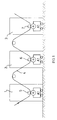
- each printing element 1, 2, 3 is traversed by a web 4 to be printed.
- a printing cylinder receiving carriage A1 is arranged in each printing element 1, 2, 3.
- Each receiving carriage A1 is equipped with a pressure cylinder in a known manner. Furthermore, each carriage A1 has a known doctor device and a known ink application device.
- a pressure roller 5, 6 or 7 is provided in each pressure element 1, 2, 3, which can be raised and lowered and presses the web 4 against the pressure cylinder of the receiving carriage A1.
- Fig. 1 the rotary printing press is shown schematically during the printing process.
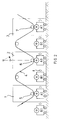
- the receiving carriages B1 are then moved along the dash-dot line S, as shown in FIG. 5. As can be seen from FIG. 6, the free spaces which have now formed on the left side of the printing units 1, 2 and 3 are occupied by new receiving carriages B2, which remain in the waiting position.
- the entire carriage group consisting of the pick-up carriages A2 and the pick-up carriages B2 is again moved in the direction of the arrow f, that is to say from left to right, whereupon the loading cycle is repeated.
- the inventor has proposed that during the process of replacing the printing cylinder receiving carriages, the entire carriage group (consisting of printing cylinder receiving carriages inside the printing units 1, 2 and 3, as well as replacement carriages, which are arranged in the waiting position in front of the printing units 1, 2 and 3) with a pendulum-like displacement movement once to the right and then move it to the left altogether, the inventor noticed that the devices for controlling and moving the receptacles can be extremely simple.
Landscapes
- Engineering & Computer Science (AREA)
- Mechanical Engineering (AREA)
- Rotary Presses (AREA)
Applications Claiming Priority (2)
| Application Number | Priority Date | Filing Date | Title |
|---|---|---|---|
| ITMI912588A IT1251899B (it) | 1991-09-27 | 1991-09-27 | Procedimento per introdurre carrelli portacilindro negli elementi di stampa di una macchina rotativa |
| ITMI912588 | 1991-09-27 |
Publications (2)
| Publication Number | Publication Date |
|---|---|
| EP0535452A1 true EP0535452A1 (fr) | 1993-04-07 |
| EP0535452B1 EP0535452B1 (fr) | 1997-01-22 |
Family
ID=11360781
Family Applications (1)
| Application Number | Title | Priority Date | Filing Date |
|---|---|---|---|
| EP92115877A Expired - Lifetime EP0535452B1 (fr) | 1991-09-27 | 1992-09-17 | Procédé pour introduire les chariots porte-cylindre à imprimer dans les unités d'impression d'une rotative d'impression |
Country Status (5)
| Country | Link |
|---|---|
| US (1) | US5301611A (fr) |
| EP (1) | EP0535452B1 (fr) |
| JP (1) | JPH07205393A (fr) |
| DE (1) | DE59207936D1 (fr) |
| IT (1) | IT1251899B (fr) |
Families Citing this family (2)
| Publication number | Priority date | Publication date | Assignee | Title |
|---|---|---|---|---|
| US6802252B1 (en) * | 2000-05-17 | 2004-10-12 | Claudio Maggio | Automatic device for replacing printing cartridges in a gravure printing machine |
| US6593953B1 (en) * | 2000-09-05 | 2003-07-15 | Hewlett-Packard Development Company, L.P. | Dual ink jet print carriage for web printing |
Citations (6)
| Publication number | Priority date | Publication date | Assignee | Title |
|---|---|---|---|---|
| US3232227A (en) * | 1962-10-19 | 1966-02-01 | Miehle Goss Dexter Inc | Apparatus for changing printing assembly |
| GB2119712A (en) * | 1982-05-06 | 1983-11-23 | Bobst Sa | Method and device for changing the printing organs in the printing units of a press |
| EP0097331A2 (fr) * | 1982-06-18 | 1984-01-04 | Windmöller & Hölscher | Dispositif pour échanger le cylindre imprimeur dans une rotative à héliogravure |
| EP0123976A2 (fr) * | 1983-04-29 | 1984-11-07 | OFFICINE MECCANICHE GIOVANNI CERUTTI S.p.A. | Chariot réglable pour cylindre à imprimer |
| FR2637222A1 (fr) * | 1988-10-05 | 1990-04-06 | Schiavi Cesare Costr Mec | Machine rotative perfectionnee a imprimer en rotogravure |
| GB2225286A (en) * | 1988-11-25 | 1990-05-30 | Schiavi Cesare Costr Mec | A trolley for print cylinder assemblies |
Family Cites Families (5)
| Publication number | Priority date | Publication date | Assignee | Title |
|---|---|---|---|---|
| US3625145A (en) * | 1969-06-05 | 1971-12-07 | Bobst Champlain Inc | Cylinder cart for exchanging cylinders on the fly |
| US3783782A (en) * | 1972-08-04 | 1974-01-08 | Faustel Inc | Revolving turret for supporting printing press cart |
| US4449450A (en) * | 1982-07-28 | 1984-05-22 | S.A. Martin | Retractable propulsion apparatus for cardboard box printing machine |
| JPH0665489B2 (ja) * | 1983-11-15 | 1994-08-24 | 大日本印刷株式会社 | 印刷機の版胴運搬兼インキ装置 |
| US5060569A (en) * | 1989-06-22 | 1991-10-29 | Didde Web Press Corporation | Apparatus for changeover of cylinders in web fed printing press |
-
1991
- 1991-09-27 IT ITMI912588A patent/IT1251899B/it active IP Right Grant
-
1992
- 1992-09-17 EP EP92115877A patent/EP0535452B1/fr not_active Expired - Lifetime
- 1992-09-17 DE DE59207936T patent/DE59207936D1/de not_active Expired - Fee Related
- 1992-09-24 US US07/950,819 patent/US5301611A/en not_active Expired - Lifetime
- 1992-09-25 JP JP4256376A patent/JPH07205393A/ja active Pending
Patent Citations (6)
| Publication number | Priority date | Publication date | Assignee | Title |
|---|---|---|---|---|
| US3232227A (en) * | 1962-10-19 | 1966-02-01 | Miehle Goss Dexter Inc | Apparatus for changing printing assembly |
| GB2119712A (en) * | 1982-05-06 | 1983-11-23 | Bobst Sa | Method and device for changing the printing organs in the printing units of a press |
| EP0097331A2 (fr) * | 1982-06-18 | 1984-01-04 | Windmöller & Hölscher | Dispositif pour échanger le cylindre imprimeur dans une rotative à héliogravure |
| EP0123976A2 (fr) * | 1983-04-29 | 1984-11-07 | OFFICINE MECCANICHE GIOVANNI CERUTTI S.p.A. | Chariot réglable pour cylindre à imprimer |
| FR2637222A1 (fr) * | 1988-10-05 | 1990-04-06 | Schiavi Cesare Costr Mec | Machine rotative perfectionnee a imprimer en rotogravure |
| GB2225286A (en) * | 1988-11-25 | 1990-05-30 | Schiavi Cesare Costr Mec | A trolley for print cylinder assemblies |
Also Published As
| Publication number | Publication date |
|---|---|
| ITMI912588A0 (it) | 1991-09-27 |
| JPH07205393A (ja) | 1995-08-08 |
| IT1251899B (it) | 1995-05-26 |
| EP0535452B1 (fr) | 1997-01-22 |
| US5301611A (en) | 1994-04-12 |
| DE59207936D1 (de) | 1997-03-06 |
| ITMI912588A1 (it) | 1993-03-27 |
Similar Documents
| Publication | Publication Date | Title |
|---|---|---|
| DE3716188A1 (de) | Verfahren und system zum behandeln mindestens einer materialbahn | |
| CH658625A5 (de) | Vorrichtung zur einstellung der laenge einer zu bedruckenden bahn in einer rollenrotationsdruckmaschine. | |
| DE4327646C5 (de) | Breiten-Einstellverfahren für eine Papierbahn sowie damit ausgerüstete lithographische Rotationspresse | |
| DE10309893A1 (de) | Bodenlegevorrichtung für Papiersäcke | |
| DD142435A5 (de) | Mehrfarbendruckmaschine | |
| DE19920230A1 (de) | Reinigungsvorrichtung für die graphische Industrie | |
| EP0535452B1 (fr) | Procédé pour introduire les chariots porte-cylindre à imprimer dans les unités d'impression d'une rotative d'impression | |
| EP1090754A1 (fr) | Dispositif pour échanger un manchon cylindrique à imprimer | |
| EP0581102B1 (fr) | Procédé pour transférer des feuilles et transporter des feuilles vers une unité de sortie | |
| DE3320552A1 (de) | Offset-druckpresse mit zwei druckwerken | |
| DE2365668C3 (de) | Vorrichtung zur Verarbeitung bahnförmigen Materials mit einem Rotationsdruckwerk | |
| EP1539373A1 (fr) | Dispositif de pose de fond pour sacs en papier | |
| DE2624175A1 (de) | Kinematische vorrichtung zur betaetigung und fuehrung einer druckmaschine, insbesondere einer flexodruckmaschine | |
| DE3703951C2 (de) | Wendevorrichtung für Papierstapel oder dergl. | |
| DE3312038A1 (de) | Vorrichtung zum einziehen von materialbahnen in rotationsdruckmaschinen | |
| EP1732760B1 (fr) | Groupe d'impression de machine a imprimer, muni d'un rouleau presseur | |
| DE8510718U1 (de) | Vorrichtung zum leichteren Einsetzen und Herausnehmen der Walze bei Umkehr-Tiefdruckmaschinen | |
| EP0578161A1 (fr) | Elément d'impression pour rotative d'impression avec plusieurs chariots porte-cylindre | |
| EP3530461B1 (fr) | Procédé de remplacement de plaques de pression sur un cylindre et cylindre à imprimer avec un clapet de retenue dans le tube hydraulique pour le dispositif de serrage | |
| DE81606C (fr) | ||
| DE2430472C2 (de) | Wagen an Rotationsdruckrnaschinen | |
| DE102017215502B4 (de) | Druckwerk mit einer Aufzugwechselhilfe sowie Verfahren zum Aufziehen von Aufzügen auf Druckwerkszylinder eines Druckwerks | |
| EP1567342A1 (fr) | Racle a reservoir d'encre | |
| CH658416A5 (de) | Vorrichtung zum schleifenfoermigen biegen eines fortlaufenden drahtes. | |
| EP0412318A2 (fr) | Machine sérigraphique à régime intermittent |
Legal Events
| Date | Code | Title | Description |
|---|---|---|---|
| PUAI | Public reference made under article 153(3) epc to a published international application that has entered the european phase |
Free format text: ORIGINAL CODE: 0009012 |
|
| AK | Designated contracting states |
Kind code of ref document: A1 Designated state(s): DE FR GB IT |
|
| 17P | Request for examination filed |
Effective date: 19930703 |
|
| 17Q | First examination report despatched |
Effective date: 19950104 |
|
| GRAG | Despatch of communication of intention to grant |
Free format text: ORIGINAL CODE: EPIDOS AGRA |
|
| GRAH | Despatch of communication of intention to grant a patent |
Free format text: ORIGINAL CODE: EPIDOS IGRA |
|
| GRAH | Despatch of communication of intention to grant a patent |
Free format text: ORIGINAL CODE: EPIDOS IGRA |
|
| GRAA | (expected) grant |
Free format text: ORIGINAL CODE: 0009210 |
|
| AK | Designated contracting states |
Kind code of ref document: B1 Designated state(s): DE FR GB IT |
|
| ITF | It: translation for a ep patent filed | ||
| GBT | Gb: translation of ep patent filed (gb section 77(6)(a)/1977) |
Effective date: 19970122 |
|
| REF | Corresponds to: |
Ref document number: 59207936 Country of ref document: DE Date of ref document: 19970306 |
|
| ET | Fr: translation filed | ||
| PLBE | No opposition filed within time limit |
Free format text: ORIGINAL CODE: 0009261 |
|
| 26N | No opposition filed | ||
| REG | Reference to a national code |
Ref country code: GB Ref legal event code: IF02 |
|
| PGFP | Annual fee paid to national office [announced via postgrant information from national office to epo] |
Ref country code: DE Payment date: 20070926 Year of fee payment: 16 |
|
| PGFP | Annual fee paid to national office [announced via postgrant information from national office to epo] |
Ref country code: GB Payment date: 20070828 Year of fee payment: 16 |
|
| PGFP | Annual fee paid to national office [announced via postgrant information from national office to epo] |
Ref country code: IT Payment date: 20070725 Year of fee payment: 16 |
|
| PGFP | Annual fee paid to national office [announced via postgrant information from national office to epo] |
Ref country code: FR Payment date: 20070920 Year of fee payment: 16 |
|
| GBPC | Gb: european patent ceased through non-payment of renewal fee |
Effective date: 20080917 |
|
| REG | Reference to a national code |
Ref country code: FR Ref legal event code: ST Effective date: 20090529 |
|
| PG25 | Lapsed in a contracting state [announced via postgrant information from national office to epo] |
Ref country code: IT Free format text: LAPSE BECAUSE OF NON-PAYMENT OF DUE FEES Effective date: 20080917 Ref country code: DE Free format text: LAPSE BECAUSE OF NON-PAYMENT OF DUE FEES Effective date: 20090401 |
|
| PG25 | Lapsed in a contracting state [announced via postgrant information from national office to epo] |
Ref country code: FR Free format text: LAPSE BECAUSE OF NON-PAYMENT OF DUE FEES Effective date: 20080930 |
|
| PG25 | Lapsed in a contracting state [announced via postgrant information from national office to epo] |
Ref country code: GB Free format text: LAPSE BECAUSE OF NON-PAYMENT OF DUE FEES Effective date: 20080917 |