EP0535946A2 - System zum Fördern von Gegenständen im Laufe eines Prozesses - Google Patents
System zum Fördern von Gegenständen im Laufe eines Prozesses Download PDFInfo
- Publication number
- EP0535946A2 EP0535946A2 EP92308940A EP92308940A EP0535946A2 EP 0535946 A2 EP0535946 A2 EP 0535946A2 EP 92308940 A EP92308940 A EP 92308940A EP 92308940 A EP92308940 A EP 92308940A EP 0535946 A2 EP0535946 A2 EP 0535946A2
- Authority
- EP
- European Patent Office
- Prior art keywords
- article
- filling
- starwheel
- container
- positioning
- Prior art date
- Legal status (The legal status is an assumption and is not a legal conclusion. Google has not performed a legal analysis and makes no representation as to the accuracy of the status listed.)
- Granted
Links
Images







Classifications
-
- B—PERFORMING OPERATIONS; TRANSPORTING
- B65—CONVEYING; PACKING; STORING; HANDLING THIN OR FILAMENTARY MATERIAL
- B65B—MACHINES, APPARATUS OR DEVICES FOR, OR METHODS OF, PACKAGING ARTICLES OR MATERIALS; UNPACKING
- B65B43/00—Forming, feeding, opening or setting-up containers or receptacles in association with packaging
- B65B43/42—Feeding or positioning bags, boxes, or cartons in the distended, opened, or set-up state; Feeding preformed rigid containers, e.g. tins, capsules, glass tubes, glasses, to the packaging position; Locating containers or receptacles at the filling position; Supporting containers or receptacles during the filling operation
- B65B43/54—Means for supporting containers or receptacles during the filling operation
- B65B43/60—Means for supporting containers or receptacles during the filling operation rotatable
-
- B—PERFORMING OPERATIONS; TRANSPORTING
- B67—OPENING, CLOSING OR CLEANING BOTTLES, JARS OR SIMILAR CONTAINERS; LIQUID HANDLING
- B67C—CLEANING, FILLING WITH LIQUIDS OR SEMILIQUIDS, OR EMPTYING, OF BOTTLES, JARS, CANS, CASKS, BARRELS, OR SIMILAR CONTAINERS, NOT OTHERWISE PROVIDED FOR; FUNNELS
- B67C3/00—Bottling liquids or semiliquids; Filling jars or cans with liquids or semiliquids using bottling or like apparatus; Filling casks or barrels with liquids or semiliquids
- B67C3/02—Bottling liquids or semiliquids; Filling jars or cans with liquids or semiliquids using bottling or like apparatus
- B67C3/22—Details
- B67C3/24—Devices for supporting or handling bottles
-
- B—PERFORMING OPERATIONS; TRANSPORTING
- B67—OPENING, CLOSING OR CLEANING BOTTLES, JARS OR SIMILAR CONTAINERS; LIQUID HANDLING
- B67C—CLEANING, FILLING WITH LIQUIDS OR SEMILIQUIDS, OR EMPTYING, OF BOTTLES, JARS, CANS, CASKS, BARRELS, OR SIMILAR CONTAINERS, NOT OTHERWISE PROVIDED FOR; FUNNELS
- B67C7/00—Concurrent cleaning, filling, and closing of bottles; Processes or devices for at least two of these operations
- B67C7/0006—Conveying; Synchronising
-
- B—PERFORMING OPERATIONS; TRANSPORTING
- B65—CONVEYING; PACKING; STORING; HANDLING THIN OR FILAMENTARY MATERIAL
- B65G—TRANSPORT OR STORAGE DEVICES, e.g. CONVEYORS FOR LOADING OR TIPPING, SHOP CONVEYOR SYSTEMS OR PNEUMATIC TUBE CONVEYORS
- B65G2201/00—Indexing codes relating to handling devices, e.g. conveyors, characterised by the type of product or load being conveyed or handled
- B65G2201/02—Articles
- B65G2201/0235—Containers
- B65G2201/0261—Puck as article support
-
- Y—GENERAL TAGGING OF NEW TECHNOLOGICAL DEVELOPMENTS; GENERAL TAGGING OF CROSS-SECTIONAL TECHNOLOGIES SPANNING OVER SEVERAL SECTIONS OF THE IPC; TECHNICAL SUBJECTS COVERED BY FORMER USPC CROSS-REFERENCE ART COLLECTIONS [XRACs] AND DIGESTS
- Y10—TECHNICAL SUBJECTS COVERED BY FORMER USPC
- Y10S—TECHNICAL SUBJECTS COVERED BY FORMER USPC CROSS-REFERENCE ART COLLECTIONS [XRACs] AND DIGESTS
- Y10S141/00—Fluent material handling, with receiver or receiver coacting means
- Y10S141/01—Magnetic
Definitions
- the present invention relates to a transportation processing system, suitable for filling and packaging facilities incorporating filling apparatus and packaging apparatus.
- Japanese Unexamined patent publication (Ko- kai) No. 58-82801 discloses a high speed filling apparatus for packaging bags, in which a filling apparatus is arranged for filling an article into package bags.
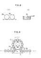
- the disclosed prior art includes a supply portion 3 including a star wheel 3A for introducing packaging bags 1 into a filling process path 2 and a feeding out portion 4 including a star wheel 4A for feeding filled packing bags 1 out of the filling process path 2, as shown in Fig. 9.
- the supply portion 3 and the feeding out portion 4 are arranged on a plane common to the filling process path 2 and the positions outside of the filling process path 2.
- the filling process path 2 is defined on a rotary table, and the areas at the periphery of the rotary table occupied by the supply portion 3 and the feeding out portion 4 become substantially large.
- the effective processing angle 0A becomes small (e.g. 260°). Therefore, in order to obtain a sufficient processing path length, the facility inherently become large.
- filling apparatuses as disclosed in Japanese Unexamined Patent publication No. 58-82801 or, in the alternative, in Japanese Unexamined patent Publication No. 56-23401.
- Theses filling apparatuses comprise a filling process path for filling an article or articles in a container and other process path for performing other processes for the container and connected to the filling process path.
- the content to be placed within the container is filled during transportation of the container.
- the container is subject other processes during transportation of the container.
- the above-mentioned other processes include a cleaning process for cleaning empty containers by pressurized air, a capping process for fitting caps on the filled containers, and a heat sealing process for forming a heat seal on the openings of the fil-
- a cleaning process for cleaning empty containers by pressurized air a capping process for fitting caps on the filled containers
- a heat sealing process for forming a heat seal on the openings of the fil-
- Article positioning apparatuses are disclosed in Japanese Unexamined Patent Publication No. 56-52197 and Japanese Unexamined Patent Publication No. 59-3760.
- This prior art includes guide pins extending from magnet devices.
- the guide pins extends through center holes of an annular metal strip or disk holders as articles to be positioned. Thereafter, the articles to be positioned are down onto the magnet device to be held thereon.
- known rotary type filling apparatuses include a rotary table and a guide members circumferentially disposed about the rotary table at regular intervals for supporting the containers.
- a supply star wheel and a feed out star wheel are provided adjacent to the rotary table.
- the containers are supplied into respective guide members so that the guide members may support the containers.
- the containers supported by the guide members are then fed out of the rotary table by the feed out star wheel.
- the opening mouth of the engaging recesses of the guide member are made larger so that supplying and taking out of the container to and from the guide member can be smoothly performed.
- the conventional guide member since the conventional guide member receives and disposed of the container from the radially outside, it may have low applicability.
- an article transporting apparatus comprises:
- the supply portion may be arranged one of inside and outside of the process path and the feeding out portion is arranged at the opposite side.
- the article may be transported through the supply portion, the process path and the feeding out portion by a magnetic force, and transferred in the condition held by the magnetic force.
- the process path may include a positioning means for positioning the article at a predetermined position.
- the supply portion and the feeding out portion are arranged in an intersecting manner relative to the annular article processing path, the area occupied by the supply portion and the feeding out portion on the circumference of the process path can be reduced to enable an increase in the effective process path length.
- the supply portion is provided at one of the inner and outer sides of the annular article process path and the feeding out portion is arranged at the other side, the area occupied by the supply portion and the feeding out portion on the circumference of the process path can be reduced to enable an increase in the effective process path length.
- the effective process range of the process path in connecting the supply portion and the feeding out portion of the annular article processing path, the effective process range of the process path can be increased to enable increasing the effective process path length without increasing the size of the facility.
- a filling apparatus comprises:
- the container may be held with a magnetic force in the filling process path and the another process path, and transferred between both paths in a condition held by the magnetic force.
- the filling process path may include a positioning means for positioning the container relative to each filling process means.
- an article positioning apparatus for positioning an article on a supporting base, comprises:
- the coupling means may comprise a positioning pin stored in eitherthe supporting base side orthe article side, a positioning hole provided at the opposite side to the positioning pin, and a pin driving magnetic member movable relative to the positioning pin so that the pin driving magnetic member applies a magnetic drawing force or a magnetic repulsive force to the positioning pin at the mating position resulting in the positioning pin engaging the positioning hole.
- an article processing apparatus comprises:
- the holder transferred to the guide member of the second rotary body is circumferentially positioned by engagement with the guide member and radially positioned by the drawing force of the magnet. Therefore, the accurate positioning can be achieved for the holder transferred to the second rotary body.
- the holder can be fed out inwardly along the guide member even at the positioned byen- gagement with the guide member.
- the holder transferred to the second rotary body can be accurately positioned and can provide the article processing apparatus with a wide range of processing applicability.
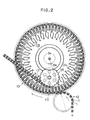
- a filling apparatus 10 is designed to fill a content, such as detergent, in a container 1 set in a container fixing member 11, and subsequently set a cap on the container 1.
- the filling apparatus 10 has an empty container infeed starwheel 12, a filling starwheel 13, a discharge starwheel 16, a discharge conveyer 17.
- the starwheels 12,13 and 16 and the discharge conveyer 17 are driven in synchronism with each other.
- a gear 23A fixed on an output shaft of a motor 23 is meshed with a gear 13A fixed on the filling starwheel 13.
- a gear 13B fixed to the filling starwheel 13 is meshed with a gear (not shown) on the discharge starwheel 16.
- the filling starwheel 13 forms an annular filling process path 13C.
- the empty container infeed starwheel 12 forms a supply portion
- the discharge starwheel 16 and the discharge conveyer 17 form a feeding out portion.
- the empty container infeed starwheel 12 is arranged at the position outside of the annularfilling process path 13C defined by the filling starwheel 13.
- the discharge starwheel 16 and the discharge conveyer 17 are arranged inside of the annular filling process path 13C.
- the feeding conveyer 17 is arranged at a different level than the filling process path 13C so that it intersects with the filling process path 13C with an ascending gradient.
- the filling starwheel 13 has sixty filling heads 13D.
- Each filling head 13D is provided with a metering device 24 and a filling device 25.
- the container 1 set to each filling head 13D is filled with a proper amount of content through a nozzle of the filling device 25 during travel from the inlet side to the outlet side of the filling process path 13C.
- the container fixing member 11 houses a ring shaped permanent magnet 11A at the bottom thereof.
- the center hole of the permanent magnet 11A serves as a first positioning hole 11B.
- the container fixing member 11 also has second positioning holes 11C at both lateral sides aligned in the diametrical direction, through the bottom.
- the filling apparatus 10 has an article transferring and holding device 40 on each filling head 13D of the filling starwheel 13.
- the article transferring and holding device 40 includes a movable base 41 and left and right stationary bases 42.
- the movable base 41 is mounted on a guide rail 43 arranged on the filling starwheel 13.
- the movable base 41 carries a cam follower 46 engaged with a movable base driving cam groove 45 supported on the outer peripheral frame 44 of the filling apparatus 10. With this construction, the movable base 41 is reciprocally movable between an outer end position and an inner end position set in the radial direction of the filling starwheel 13.
- the stationary bases 42 are respectively secured on both sides of the movable base 41.
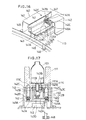
- the movable base 41 has a positioning device 47 at the outer end.
- the positioning device 47 includes an article fixing magnet 47A formed of a ring-shaped permanent magnet for magnetically drawing and fixing the permanent magnet 11A of the containerfixing member 11, and a first positioning pin 47B enclosed in the central hole portion of the article fixing magnet 47A.
- a permanent magnet 47C is provided at the lower end of the first positioning pin 47B.
- a magnet supporting portion 42A provided on the stationary base 42 has a pin drive magnet 47D formed with a permanent magnet.
- the pin drive magnet 47D is opposed to the permanent magnet 47C of the first positioning pin 47B when the filling head 13D is positioned in a transferring region (OB) with the empty container infeed starwheel 12 and the discharge starwheel 16 in the circulating line of the filling starwheel 13 and the movable base 41 is set at the inner end position to apply a magnetic repulsive force to the permanent magnet 47C so that the first positioning pin 47B projects upwardly.
- the first positioning pin 47B engages with the first positioning hole 11B of the containerfixing member 11 at this position.
- the pin drive magnet 47D will never oppose the permanent magnet 47C of the first positioning pin 47B so that a repulsive magnetic force will never act. Therefore, the first positioning pin 47B is enclosed in the central hole portion of ring-shaped article fixing magnet 47A by its own weight. Therefore, as will be discussed later, the first positioning pin 47B is released from engagement with the first positioning hole 11B of the container fixing member 11. It should be noted the permanent magnet 47C of the first positioning pin 47B and the pin drive magnet 47D will oppose the same pole (for example, S pole) when they oppose each other so that the above-mentioned magnetic repulsive force can be generated.
- the ring-shaped article fixing magnet47A forms the magnetic fixing means forfixing the containerfixing member 11 onto the movable base 41.
- the first positioning pin 47B, the first positioning hole 11B and the pin drive magnet 47D form a magnetic cooperating means for cooperating the container fixing member 11 with the filling starwheel 13.
- the container fixing member 11 cooperates with the movable base 41 by the positioning pin 47B of the magnetic cooperating means after being fixed about the positioning center on the movable base 41 by the magnetic fixing means.
- the article fixing magnet 47A and the permanent magnet 11A of the container fixing member 11 draw to each other so as to substantially align the centers of the magnets to each other.
- the container fixing member 11 is roughly positioned in self-aligned fashion about the positioning center on the movable base 41. Accordingly, the containerfixing member 11 cooperates with movable base 41 by positioning pin 47B of the magnetic cooperation means after being roughly positioned on the movable base 41 in self-aligned fashion by the magnetic fixing means. Namely, since, in advance of cooperating operation by the positioning pin 47B, the containerfixing member 11 is roughly positioned on the movable base 41 by the magnetic fixing means, the positioning operation can be made simple and easy.
- the movable base 41 has a permanent magnet at the inner end for magnetically drawing the permanent magnet 11A of the container fixing member 11.
- the left and right stationary bases 42 have second positioning pins 42C received in recesses 42B. Permanent magnets 42D are provided at the lower ends of the respective second positioning pins 42C.
- each of the left and right magnet supporting portions 41C provided on the movable base 41 are provided with three pin drive magnets 49A, 49B and 49C formed with permanent magnets.
- the pin drive magnetic 49A and 49C are adapted to oppose the permanent magnet 42D of the second positioning pin 42C to apply a magnetic drawing force to the permanent magnet 42D when the movable base 41 is set at the outer and inner end positions. By the magnetic drawing force, the second positioning pin 42C is retracted within the recess 42B.
- the pin drive magnet 49B is adapted to oppose the permanent magnet 42D of the second positioning pin 42C to apply the magnetic repulsive force to the permanent magnet 42D so that the second positioning pin 42C is projected out of the recess when the movable base 41 is positioned at the intermediate position between the outer and inner end positions.
- the second positioning pin 42C as projected from the recess engages the second positioning hole 11C of the container fixing member 11.
- the permanent magnet 42D of the second positioning pin 42C and the pin drive magnets 49A and 49C oppose opposite poles (S pole and N pole) at opposing positions to generate the magnetic drawing force as set forth above.
- the permanent magnet 42D of the second positioning pin 42C and the pin drive magnet 49B oppose the same pole as opposed to each other so as to generate the magnetic repulsive force.
- the empty container infeed starwheel 12 and the discharge starwheel 16 respectively have article transferring and holding devices which have substantially the same construction.
- the article transferring and holding device 50 of the discharge starwheel 16 will be discussed below as an example.
- the article transferring and holding device 50 has an article drawing magnet 51 arranged on the notched outer periphery of the discharge starwheel 16.
- the recessed portion of the article drawing magnet 51 is engageable with the inner end of the movable base 41 which forms the article transferring and holding device 40 of the fitting starwheel 13.
- the magnetic force of the article drawing magnet 51 is set to be greater than the magnetic force of the permanent magnet 48 of the movable base 41.
- the container fixing member 11 is transferred from the empty container starwheel 12 to the filling starwheel 13 and held by the filling starwheel 13 by the article transporting and holding device 40. (see Fig. 5)
- the movable base 41 When the filling head 13D of the filling starwheel 13 is positioned at a transferring position (A) where the empty container infeed starwheel 12 and the filling starwheel 13 are approached by each other, the movable base 41 is set at the outer end position. Then, the outer end of the movable base 41 engages with the recessed portion of the article drawing magnet provided on the notched outer periphery of the empty container infeed starwheel 12. At this time, the empty container infeed starwheel 12 draws the permanent magnet 11A of the container fixing member 11 on the article drawing magnet to hold the container fixing member.
- the positioning device 47 of the movable base 41 maintains the first positioning pin 47B in the retracted position and draws the permanent magnet 11A of the container fixing member 11 on the empty container infeed starwheel 12 to catch the container fixing member by the ring-shaped article drawing magnet 47A.
- the permanent magnet 11A of the container fixing member 11 is drawn by both the article drawing magnet 47A and the article drawing magnet of the empty container infeed starwheel 12.
- the magnetic force of the article drawing magnet 47A is designed to have a greater magnetic force than that of the article drawing magnet of the empty container infeed starwheel 12, the containerfixing member 11 is transferred from the empty container infeed starwheel 12 to the filling starwheel 13 without causing displacement due to vibration.
- the movable base 41 When the filling head 13D of the filing starwheel 13 reaches the filling operation start position (B) from the above-mentioned transferring position (A), the movable base 41 is placed at the inner end position. At this time, the positioning device 47 of the movable base 41 projects the first positioning pin 47B so that the first positioning pin 47B may engage with the first positioning hole 11B of the container fixing member 11 to complete the positioning of the containerfixing member 11. Then, the container fixing member 11 is held on the movable base 41. By this, the permanent magnet 11A of the container fixing member 11 is drawn by the article drawing magnet 47A and held when the filling starwheel 13 is rotated. Also, the containerfixing member 11 is positioned by the first positioning pin 47B to move along the filling process path 13C.
- the movable base 41 shifts from the inner end position to the outer end position.
- the second positioning pins 42C of the stationary base 42 project to engage with two positioning holes 11C of the container fixing member 11 to hold the container fixing member.
- the positioning device 47 of the movable base 41 retracts the first positioning pin 47B so as to release engagement between the first positioning pin 47B and the first positioning hole 11 B of the containing fixing member 11.
- the movable base 41 shifts to the outer end position leaving the container fixing member 11 on the stationary base 42. From this position, the above-mentioned operation (A-1) is restarted to drawing and catching the new container fixing member 11 by the article drawing magnet 47A of the positioning device 47.
- the second positioning pins 42C engaging with the second positioning holes 11C of the container fixing member 11 are retracted.
- the container fixing member 11 is moved to a transporting position (D) at which the filling starwheel 13 and the discharge starwheel 16 approach each other in the condition where it is drawn and held by the permanent magnet 48 of the movable base 41. (see Figs. 3 and 5)
- the inner end of the movable base 41 engages with the recessed portion of the article drawing magnet 51 provided on the notched outer peripheral portion of the discharge starwheel 16.
- the permanent magnet 11A of the container fixing member 11 is drawn by both the permanent magnet 48 and the article drawing magnet 51 of the discharge starwheel 16, simultaneously.
- the article drawing magnet 51 is designed to have a greater magnetic force than that of the permanent magnet 48, the container fixing member 11 can be transferred from the filing starwheel 13 to the discharge starwheel 16 without causing displacement due to vibration.
- the discharge conveyer 17 is designed to mount the containerfixing member 11 on a transporting belt 81 which travels a given transporting path, for transportation, as shown in Fig. 4.
- the discharge conveyer 17 is arranged on an article guiding magnet 83 via a non-magnetic belt receptacle 82 on the lower position along the article transporting path by the transporting belt 81.
- the article guiding magnet 83 can be placed with a magnetic body, such as an iron plate.
- the feeing out conveyer 17 is arranged to overlap the upstream end of the transporting belt 81 with the notched outer peripheral portion of the discharge starwheel 16 to define the transferring position between the discharge starwheel 16 and the discharge conveyer 17 at this overlapping position.
- the article guiding magnet 83 is provided greater magnetic force than that of the article drawing magnet 51 of the discharge starwheel 16.
- the transferring position where the discharge starwheel 16 and the discharge conveyer 17 overlap the permanent magnet 11A of the container fixing member 11 is drawn both of the article drawing magnet 51 of the discharge starwheel 16 and the article guiding magnet 83 of the discharge conveyer 17.
- the magnetic force of the article guiding magnet 83 is greater than that of the article drawing magnet 51 of the discharge starwheel 16, the container fixing member 11 is transferred to the discharge conveyer 17 without causing displacement due to vibration.
- the container fixing member 11 is transported with the transporting belt 81 with the permanent magnet 11A thereof drawn on the article guiding magnet 83.
- the feeding converter 17 is arranged to intersecting with the annular filling process path 13C, the area occupied by the discharge starwheel 16 and the discharge conveyer 17 on the circumference of the filling process path 13C become small. As a result, the effective process angle of the filling process path 13C can be made greater.
- the empty container infeed starwheel 12 is arranged outside with respect to the annularfilling process path 13C and the discharge starwheel 16 and the discharge conveyer 17 are arranged inside with respect to the annular filling process path 13C, the container supply portion and the container feeding out portion are never arranged at one of the inner and outer sides of the filling process path 13C. Therefore, the area to be occupied by the empty container infeed starwheel 12m, the discharge starwheel 16 and the discharge conveyer 17 become small so that the effective process range of the filling process path 13C can be expanded.
- the effective processing angle 0A (318° in the shown embodiment)can be increased so as to allow a longer process path without increasing the size of the facility.
- the container fixing member 11 When the container fixing member 11 is transferred through respective starwheels 12,13,16 and the discharge conveyer 17, the container fixing member 11 is held magnetically by the article transferring and holding devices 40 and 50, and transferred in a position held by the magnetic force, the container fixing member 11 and the container 1 can be transferred in the stable attitude without causing displacement due to vibration, with simple construction.
- the container fixing member 11 and the container 1 can be accurately positioned with respect to the filling device 25 of the filing head 13D with simple construction.
- a magnet or magnetic body can be contained in the container 1 per se so that each article transferring and holding device 40 and 50 hods this magnet on the magnetic body.
- the magnet provided in the article transferring and holding device 40 and 50 can be an electromagnet.
- the invention can be implemented by forming a unit transporting apparatus 90 with the supply portion, the process path and the feeding out portion and connecting a plurality of transporting apparatus 90 as shown in Figs. 8(A) and 8(B).
- Fig. 8(A) shows the arrangement, in which the units are connected in the horizontal direction.
- Fig. 8(B) shows the arrangement in which the units are connected in the vertical direction.
- the process portion may be established to perform a plurality of kinds of processes, such as an empty container cleaning process, a filling process, a cap setting process, and a heat sealing process.
- the annular process path is not limited to the single circumferential cycle but can be two or more circumferential cycles.
- a filling apparatus 10 is designed to fill a content, such as detergent in a container 101 set in a container fixing member 111, and subsequently set a cap on the container 101.
- the filling apparatus 110 has an empty container infeed starwheel 112, a filling starwheel 113, a first intermediate starwheel 114, a capping starwheel 115, a second intermediate starwheel 116, a discharge conveyer 117.
- the filling starwheel 113 and the cap starwheel 116 are supported for rotation about a center post 118.
- the intermediate starwheels 114 and 116 are supported for rotation about branch shafts 121 and 122 supported on the center pole 118 via a supporting member 119.
- Respective of the starwheels 112 - 116 and the discharge conveyer 117 are driven in synchronism with each other.
- a gear 123A fixed on an output shaft of a motor 123 is meshed with a gear 113A fixed on the filling starwheel 113.
- a gear 113B fixed to the filling starwheel 113 is meshed with a gear 114A fixed on the first intermediate starwheel 114.
- Agear 114B fixed on the first intermediate starwheel 114 is meshed with a gear 115A fixed to the capping starwheel 115.
- a gear 116A fixed to the second intermediate starwheel 116 is meshed.
- the filling starwheel 113 has sixty filling heads 113D.
- Each filling head 113D is provided with a metering device 124 and a filling device 125.
- the container 101 set to each filling head 113D is filled with a proper amount of content through a nozzle of the filling device 125 during travel from the inlet side to the outlet side of the filling process path 113C.
- the capping starwheel 115 contains twenty capping heads.
- Each capping head 115D is provided with a supporting plate elevating guide 128, a container positioning member 129, a cap setting device 131 and a cap setting device elevating guide 132.
- the container 101 set in each capping head 115D is risen together with the supporting plate 127 which is elevated by a supporting plate elevating cam 133 and positioned within a ring-shaped guide of the container positioning member 129, while the containertrav- els from the inlet side to the outlet side of the capping process path 115C.
- the cap setting device 131 of each capping head 115D is risen by the cap setting device elevating cam 131 while it travels from the inlet side to the outlet side of the capping process path 115C, so as to catch a cap supplied from a cap supply table 135 and threadingly set the cap onto the container 101 which is positioned by the container positioning member 129 as set forth above.
- the filling process path 113C on the filling starwheel 113 and the capping process path 115C on the capping starwheel 115 are formed essentially in annular configuration and arranged in the positional relationship that one is positioned inside relative to the other.
- a plurality of (sixty) filling heads 113D for filling content in the containers 101 transported on the filling process path 113C are provided, and a plurality of (twenty) capping heads 115D for setting cap on the containers 101 transported on the capping process path 115C are provided.
- the container fixing member 111 houses a ring shaped permanent magnet 111A at the bottom thereof.
- the center hole of the permanent magnet 111A serves as a first positioning hole 111 B.
- the container fixing member 111 also has second positioning holes 111C at both lateral sides aligned in the diametrical direction, through the bottom.
- the filling apparatus 110 has an article transferring and holding device 140 on each lower part of each filling head 113D of the filling starwheel 113.
- the article transferring and holding device 140 includes a movable base 141 and left and right stationary bases 142.
- the movable base 141 is mounted on a guide rail 143 arranged on the filling starwheel 113.
- the movable base 141 carries a cam follower 146 engaged with h a movable base driving cam groove 145 supported on the outer peripheral frame 144 of the filling apparatus 110.
- the movable base 141 is reciprocally movable between an outer end position and an inner end position set in the radial direction of the filling starwheel 113.
- the stationary bases 142 are respectively secured on both sides of the movable base 141.
- the movable base 141 has a positioning device 147 at the outer end.
- the positioning device 147 includes an article fixing magnet 147A formed of a ring-shaped permanent magnet for magnetically drawing and fixing the permanent magnet 111A of the container fixing member 111, and a first positioning pin 147B enclosed in the central hole portion of the article fixing magnet 147A.
- a permanent magnet 147C is provided at the lower end of the first positioning pin 147B.
- a magnet supporting portion 142A provided on the stationary base 142 has a pin drive magnet 147D formed with a permanent magnet.
- the pin drive magnet 147D is opposed to the permanent magnet 147C of the first positioning pin 147B when the filling head 113D is positioned in a transferring region with the empty container infeed starwheel 112 and the first intermediate starwheel 114 in the circulating line of the filling starwheel 113 and the movable base 141 is set at the inner end position to apply a magnetic repulsive force to the permanent magnet 147C so that the first positioning pin 147B projects upwardly.
- the first positioning pin 147B engages with the first positioning hole 111 B of the container fixing member 111 at this position.
- the pin drive magnet 147D will never oppose the permanent magnet 147C of the first positioning pin 147B so that a repulsive magnetic force will never act. Therefore, the first positioning pin 147B is enclosed in the central hole portion of ring-shaped article fixing magnet 147A by its own weight. Therefore, as will be discussed later, the first positioning pin 147B is released from engagement with the first positioning hole 111B of the container fixing member 111.
- the permanent magnet 147C of the first positioning pin 147B and the pin drive magnet 147D will oppose the same pole (for example, S pole) when they oppose each other so that the above-mentioned magnetic repulsive force can be generated.
- the ring-shaped article fixing magnet 147A forms the magnetic fixing means for fixing the container fixing member 111 onto the movable base 141.
- the first positioning pin 147B, the first positioning hole 111B and the pin drive magnet 147D form a magnetic cooperating means for cooperating the container fixing member 111 with the filling starwheel 113.
- the container fixing member 111 cooperates with the movable base 141 by the positioning pin 147B of the magnetic cooperating means after being fixed about the positioning center on the movable base 141 by the magnetic fixing means.
- the article fixing magnet 147A and the permanent magnet 111A of the container fixing member 111 draw to each other so as to substantially align the centers of the magnets to each other.
- the container fixing member 111 is roughly positioned in self-aligned fashion about the positioning center on the movable base 141.
- the containerfixing member 111 cooperates with movable base 141 by positioning pin 147B of the magnetic cooperation means after being roughly positioned on the movable base 141 in self-aligned fashion by the magnetic fixing means.
- the positioning operation can be made simple and easy.
- the movable base 141 has a permanent magnet 148 at the inner end for magnetically drawing the permanent magnet 111A of the container fixing member 111.
- the left and right stationary bases 142 have second positioning pins 142C received in recesses 142B. Permanent magnets 142D are provided at the lower ends of the respective second positioning pins 142C.
- each of the left and right magnet supporting portions 141C provided on the movable base 141 is provided with three pin drive magnets 149A, 149B and 149C formed with permanent magnets.
- the pin drive magnetic 149A and 149C are adapted to oppose the permanent magnet 142D of the second positioning pin 142C to apply a magnetic drawing force to the permanent magnet 142D when the movable base 141 is set at the outer and inner end positions. By the magnetic drawing force, the second positioning pin 142C is retracted within the recess 142B.
- the pin drive magnet 149B is adapted to oppose the permanent magnet 142D of the second positioning pin 142C to apply the magnetic repulsive force to the permanent magnet 142D so that the second positioning pin 142C is projected out of the recess when the movable base 141 is positioned at the intermediate position between the outer and inner end positions.
- the second positioning pin 142C as projected from the recess engages the second positioning hole 111C of the container fixing member 111.
- the permanent magnet 142D of the second positioning pin 142C and the pin drive magnets 149A and 149C oppose opposite poles (S pole and N pole) at opposing positions to generate the magnetic drawing force as set forth above.
- the permanent magnet 142D of the second positioning pin 142C and the pin drive magnet 149B oppose the same pole as opposed to each other so as to generate the magnetic repulsive force.
- the empty container infeed starwheel 112 and the first intermediate starwheel 114 respectively have article transferring and holding devices which have substantially the same construction.
- the article transferring and holding device 150 of the first intermediate starwheel 114 will be discussed below as an example.
- the article transferring and holding device 150 has an article drawing magnet 151 arranged on the notched outer periphery of the first intermediate starwheel 114.
- the recessed portion of the article drawing magnet 151 is engageable with the inner end of the movable base 141 which forms the article transferring and holding device 140 of the filling starwheel 113.
- the magnetic force of the article drawing magnet 151 is set to be greater than the magnetic force of the permanent magnet 148 of the movable base 141.
- the container fixing member 111 is transferred from the empty container starwheel 112 to the filling starwheel 113 and held by the fitting starwheel 113 by the article transporting and holding device 140. (see Fig. 15)
- the movable base 141 When the filling head 113D of the filling starwheel 113 is positioned at a transferring position (A) where the empty container infeed starwheel 112 and the filling starwheel 113 are approached by each other, the movable base 141 is set at the outer end position. Then, the outer end of the movable base 141 engages with the recessed portion of the article drawing magnet provided on the notched outer periphery of the empty container infeed starwheel 112. At this time, the empty container infeed starwheel 112 draws the permanent magnet 111A of the container fixing member 111 on the article drawing magnet to hold the container fixing member.
- the positioning device 147 of the movable base 141 maintains the first positioning pin 147B in the retracted position and draws the permanent magnet 111A of the container fixing member 111 on the empty container infeed starwheel 112 to catch the containerfixing member by the ring-shaped article drawing magnet 147A.
- the permanent magnet 111A of the container fixing member 111 is drawn by both the article drawing magnet 147A and the article drawing magnet of the empty container infeed starwheel 112.
- the magnetic force of the article drawing magnet 147A is designed to have a greater magnetic force than that of the article drawing magnet of the empty container infeed starwheel 112, the container fixing member 111 is transferred from the empty container infeed starwheel 112 to the filling starwheel 113 without causing displacement due to vibration.
- the movable base 141 When the filling head 113Dofthe fifing starwheel 113 reaches the filling operation start position (B) from the above-mentioned transferring position (A), the movable base 141 is placed at the inner end position. At this time, the positioning device 147 of the movable base 141 projects the first positioning pin 147B so that the first positioning pin 147B may engage with the first positioning hole 111B of the container fixing member 111 to complete the positioning of the container fixing member 111. Then, the containerfixing member 111 is held on the movable base 141. By this, the permanent magnet 111A of the containerfixing member 111 is drawn by the article drawing magnet 147A and held when the filling starwheel 113 is rotated. Also, the container fixing member 111 is positioned by the first positioning pin 147B to move along the filling process path 113C.
- the movable base 141 shifts from the inner end position to the outer end position.
- the second positioning pins 142C of the stationary base 142 project to engage with two positioning holes 111C of the container fixing member 111 to hold the containerfixing member.
- the positioning device 147 of the movable base 141 retracts the first positioning pin 147B so as to release engagement between the first positioning pin 147B and the first positioning hole 111B of the containing fixing member 111.
- the movable base 141 shifts to the outer end position leaving the container fixing member 111 on the stationary base 142. From this position, the above-mentioned operation (A-1) is restarted to drawing and catching the newcontainerfix- ing member 111 by the article drawing magnet 147A of the positioning device 147.
- the second positioning pins 142C engaging with the second positioning holes 111C of the container fixing member 111 are retracted.
- the container fixing member 111 is moved to a transporting position (D) at which the filling starwheel 113 and the first intermediate starwheel 114 approach each other in the condition where it is drawn and held by the permanent magnet 148 of the movable base 141. (see Figs. 12 and 15)
- the inner end of the movable base 141 engages with the recessed portion of the article drawing magnet 151 provided on the notched outer peripheral portion of the first intermediate starwheel 114.
- the permanent magnet 111A of the container fixing member 111 is drawn by both the permanent magnet 148 and the article drawing magnet 151 of the first intermediate starwheel 114, simultaneously.
- the article drawing magnet 151 is designed to have a greater magnetic force than that of the permanent magnet 148, the containing fixing member 111 can be transferred from the filing starwheel 113 to the first intermediate starwheel 114 without causing displacement due to vibration.
- the permanent magnet 111A of the container fixing member 111 is drawn and held by the article drawing magnet 151 of the first intermediate starwheel 114.
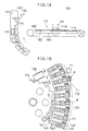
- a transferring and holding device 160 of the capping starwheel 115 has an article drawing magnet 161 on the supporting plate 127 of each capping head 115D, as shown in Fig. 13.
- the supporting plate 127 is designed to be engageable with a recess of the article drawing magnet 151 provided on the notched outer periphery of the first intermediate starwheel 114.
- the article drawing magnet 161 is provided with a magnetic force greater than that of the article drawing magnet 151.
- An article transferring and holding apparatus 170 of the second intermediate starwheel 116 has an article drawing magnet 161 on the notched outer periphery of the second intermediate starwheel 116, as shown in Fig. 14.
- the recessed portion of the article drawing magnet 171 is engageable with the support plate 127 of the capping starwheel 115.
- the article drawing magnet 171 is provided with a greater magnetic force than that of the article drawing magnet 161 of the supporting plate 127.
- the container fixing member 111 is transferred from the first intermediate starwheel 114 to the cap starwheel 115 by the article transferring and holding apparatus 150 and 160, and held in the capping starwheel 115. (see Fig. 13).
- the recessed portion of the article drawing magnet 151 of the first intermediate starwheel 114 and the support plate 127 of the capping starwheel 115 are engaged to each other.
- the permanent magnet 111A of the containerfixing member 111 is draw by both of the article drawing magnet 151 and the article drawing magnet 161 of the support plate 127 simultaneously.
- the container fixing member 111 is transferred from the first intermediate starwheel 114 to the capping starwheel 115 without causing displacement due to vibration.
- the cap starwheel 115 When the cap starwheel 115 is rotated, the permanent magnet 111A of the container fixing member 111 is drawn and held by the article drawing magnet 127 of the support plate 127. At this condition, the container fixing member 111 moves along the capping process path 115C.
- the support plate 127 of the capping starwheel 115 and the recessed portion of the article drawing magnet 171 of the second intermediate starwheel 116 are engaged with each other.
- the permanent magnet 111A of the container fixing member 111 is drawn by both the article drawing magnet 161 if the supporting plate 127 and the article drawing magnet 171 of the second intermediate starwheel 116 simultaneously. Since the article drawing magnet 171 is provided with a greater magnetic force than that of the article drawing magnet 161, the container fixing member 111 is transferred from the capping starwheel 115 to the second intermediate starwheel 116 without causing displacement due to vibration.
- the discharge conveyer 117 is designed to mount the container fixing member 111 on a transporting belt 181 which travels a given transporting path, for transportation, as shown in Fig. 14.
- the discharge conveyer 117 is arranged on an article guiding magnet 183 via a non-magnetic belt receptacle 182 on the lower position along the article transporting path by the transporting belt 181.
- the article guiding magnet 183 can be placed with a magnetic body, such as an iron plate.
- the discharge conveyer 117 is arranged to overlap the upstream end of the transporting belt 181 with the notched outer peripheral portion of the second intermediate starwheel 116 to define the transferring position between the second intermediate starwheel 116 and the discharge conveyer 117 at this overlapping position.
- the article guiding magnet 183 is provided greater magnetic force than that of the article drawing magnet 151 of the second intermediate starwheel 116.
- the transferring position where the second intermediate starwheel 116 and the discharge conveyer 117 overlap the permanent magnet 111A of the container fixing member 111 is drawn both of the article drawing magnet 171 of the second intermediate starwheel 116 and the article guiding magnet 183 of the discharge conveyer 117.
- the magnetic force of the article guiding magnet 183 is greater than that of the article drawing magnet 151 of the second intermediate starwheel 116, the container fixing member 111 is transferred to the discharge conveyer 117 without causing displacement due to vibration.
- the container fixing member 111 is transported with the transporting belt 181 with the permanent magnet 111A thereof drawn on the article guiding magnet 183.
- the second positioning pin 142C provided on the stationary base 142 of the article transferring and holding device 140 can be designed so as not to be driven by the pin drive magnets 149A - 149C, and is driven by contacting a cam follower 301 onto a cam 302 provided on the outer peripheral frame 144 of the filling apparatus 110 to engage and release the engagement with the second positioning holes 111C of the container fixing member 111.
- Respective of the process path of the filling process path 113C and the capping process path 115C are provided with a plurality of filling heads 113D and the capping heads 115D. Therefore, high productive performance in the filling process and capping process can be obtained.
- Respective process paths 113C and 115C are formed into the annular configuration with a plurality of filling heads 113D and 115D and arranged in the relationship that one is arranged inside of the other. Therefore, the installation space of the overall construction of the filling apparatus may be reduced.
- the container fixing member 111 When the container fixing member 111 is transferred through respective starwheels 112 - 116and the discharge conveyer 117, the container fixing member 111 is held magnetically by the article transferring and holding devices 140, 150,160 and 170, and transferred in a position held by the magnetic force, the container fixing member 111 and the container 101 can be transferred in the stable attitude without causing displacement due to vibration, with simple construction.
- the positioning device 147 is provided in the filling process path 113C of the filling starwheel 113, the container fixing member 111 and the container 101 can be accurately positioned with respect to the filling device 125 of the filing head 113D with simple construction.
- a magnet or magnetic body can be contained in the container 101 per se so that each article transferring and holding device 140,150,160 and 170 holds this magnet or the magnetic body.
- the magnet provided in the article transferring and holding device 140,150,160 and 170 can be an electromagnet.
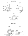
- the filling process path 191 and the other process path 192 can be in reverse directions as shown in Fig. 18(A), 18(C) and can be in the same direction as shown in Fig. 18(B).
- the filling process path 191 and other process paths 192A - 192C ... can be arranged on a common plane as shown in Fig. 19(A), or can be in a vertical two level arrangement as shown in Fig. 19(B).
- the filling process path 191 can be arranged at the upstream side of the other process path 192, or, in the alternative, at the downstream side. In the further alternative, the filling process path 191 can be arranged at the intermediate position between two other process paths 192. At this time, the path 194 of the leading process can be arranged outside the path 195 of the following process as shown in Fig. 20(A), or, in the alternative, inside of the latter as shown in Fig. 20(B).
- the patterns of the filling process path 191 and the other process path 192 can be a circular annular configuration as shown in Fig. 21(A), an elliptic annular configuration as shown in Fig. 21(B), a quadrangular annular configuration as shown in Fig. 21 (C), a composite configuration of the circular annular, elliptic annular and quadrangular configurations as shown in Fig. 21(D), or any other configuration.
- an empty container 202 received in a holder 201 is designed to be transported from an upstream side to a transferring position 204 by a transporting conveyer 203.
- the holders 201 transported on the transporting conveyer 203 are spaced apart from each other by engaging with a timing screw 205.
- the holders 201 provide the given intervals by the timing screw 205 are picked from the transporting conveyer 203 by a transferring device 204. Then, the holders 201 are transferred to a rotary table 207 of a rotary filling apparatus 206 at a transferring position A.
- a not shown filling nozzle which is rotatable with the rotary table in integral fashion is provided. While the rotary table 207 is rotated over one cycle in the clockwise direction, the container 202 in the holder 201 can be filled with a filling liquid by the filling nozzle.
- a rotary capper208 for setting a cap on the upper end of the container 202 is provided on the inner side of the rotary filling apparatus 206.
- the container 202, for which filling operation by the rotary filling apparatus 206 is completed, is transferred from the rotary table 207 of a rotary table 210 of the rotary capper 208 by a first transferring mechanism 209 which is provided inside of the transferring position A.
- the rotary capper 208 includes a plurality of capping heads (not shown)above the rotary table 210. While the rotary table 210 is driven in the counterclockwise direction, the cap is set on the upper end of the container 202 by the capping head.
- the container 202 in the holder 201, for which setting of the cap by the rotary capper 208 is completed, is ejected to a discharge conveyer 212 by a second transferring mechanism 211 provided adjacent the rotary capper 208.
- the holder 201 of the present embodiment receiving the container 202 is formed into a bottomed cylindrical configuration and provided a parallelpiped outer circumferential configuration.
- flat surfaces 201a at four portion on the outer circumferential portion and the bottom have plate form magnets 215 buried therein.
- the magnetic poles of these magnets 215 are the same as that on the surface of the holder 201.
- the rotary table 207 of the rotary filling apparatus 206 is formed with an annular plate member.
- Guide members 216 for radially guiding the holders 201 are provided on the upper surface of the rotary table 207 with circumferential regular intervals.
- the filling nozzles (not shown) are provided above the respective guide members 216.
- Each guide member 216 comprises mutually parallel plate members 216a and 216b. These are fixed on the upper surface of the rotary table 207 in radially oriented positions. While each of the guide member 216 on the rotary table 207 travels across the transferring position A in the clockwise direction, the holders 201 are pushed for insertion from the radially outside by the transferring device 204 for transferring.
- each holder 201 thus transferred to the guide member 216 at the transferring position A is grasped by both plate members 216a and 216b at the front and rear faces of the outer periphery thereof. Accordingly, each holder 201 can be accurately positioned at the circumferential position on the rotary table 207. On the other hand, the holder 201 is held movable in the radial direction by both plate members 216a and 216b.
- strip form magnets M1 are fixed along the transporting paths of the respective guide members 216.
- the tip end portion M1a and the-trailing end M1b of the magnet M1 are overlapped in the circumferential direction at the transferring position A.
- the guide member 216 provided on the rotary table 207 extends substantially in perpendicular to the magnet M1. Accordingly, the holder 201 transferred to the guide member 216 at the transferring position A is transported in the position drawn by the magnet M1. By drawing the holder 201 in the guide member 216 by the magnet M1, the holder 201 can be positioned at the predetermined radial position on the rotary table 207.
- the holder201 is restricted at the front and rear face relative to the transporting direction by the plate members 216a and 216b of the guide member 216, and drawn by the magnet M1. Therefore, the container 202 in the holder 201 transferred to the rotary table 207 can be accurately positioned in the circumferential and radial directions.
- the trailing end M1b of the magnet M1 is connected to an arc shaped magnet M2 provided at the lower position of the rotary table 207 of the first transferring mechanism 209.
- the magnet M2 is connected to an arc shaped magnet M3 provided at the lower position of the rotary table 210 of the rotary capper 208.
- the magnet M3 is connected to an arc shaped magnet M4 provided at the lower position of a rotary table 218 of the second transferring mechanism 211.
- the end of the magnet M4 is positioned overlapping with the end of the discharge conveyer 212. It should be noted thatthe magnets Ml - M4 are provided with different poles than the magnetic pole of the magnet 215 buried in the holder 201.
- the magnets Ml - M4 are provided sequentially. Therefore, the holder 201 transferred at the transferring position A can be transported through these magnets Ml - M4 in the position drawn by them. By this, loosening of the holder from respective of the rotary tables 207, 217, 210 and 218 during transportation can be successfully prevented. Also, with these magnets Ml - M4, the radial position of the holder 201 can be accurately maintained. Furthermore, in the present embodiment, since the discharge conveyer 212 comprises a magnetic conveyer, the holder 201 will never slip out from the discharge conveyer 212.
- the transferring device 204 has a support frame 219.
- the support frame 219 is provided with a rotary body 220 which is rotatable.
- the rotary body 220 is designed for rotation in synchronism with the rotary table 207 of the rotary filling apparatus 206.
- the rotary body 220 includes a vertical shaft 221 rotatably provided on the support frame 219 and upper and lower two discs 220a and 220b mounted at the upper end of the vertical shaft 221.
- rotary shafts 222 are provided with circumferential regular intervals on both disks 220a and 220b.
- Upper and lower ends of each rotary shaft 222 extend through both discs 220a and 220b.
- an arm 223 is pivotally mounted on the outer peripheral portion of the rotary shaft 222 positioned between the discs 220a and 220b.
- each arm 223 On the tip end of each arm 223, a rotary shaft 224 is extended vertically in rotatable fashion. On the lower end of each rotary shaft 224 extending through the arm 223, a plate form holding member225 is connected with a bracket.
- the cross-sectional configuration of the holding member 225 is conformed with the one planar surface 201a of the holder 201 and both corners thereof.
- the lower reverse surface of the holding member 225 engaging with the planar surface 201a of the holder 201 has a magnet 215' having an opposite polarity to that of the magnet 215 buried in the holder201. Accordingly, by engaging the holding member 225 onto the outer periphery of the holder 201 on the discharge conveyer 203, the holder can be drawn and held by the magnet 215' provided on the holding member 225.
- the holding member 225 is rotatable about the rotary shaft 224 by a rotating mechanism 228 cooperating with the rotary body 220.
- the arm 223 mounted on the holding member 225 may pivot or swing in the forward and reverse directions by a swing mechanism 229 cooperating with the rotary body 220.
- the rotary mechanism 228 and the swing mechanism 229 in cooperation with the rotary body 220, the arm 223 is driven to swing and the holding member225 is rotated at the respective rotational section of the rotary body 220.
- the holder 201 is picked from the transportation conveyer 203 and supplied to the transferring position A by the holding members 225.
- an annular mounting base 226 is fixedly provided below the path of the motion of each holding member225.
- the fixed base 226 supports the bottom of the holder 201 held by each holding member 225.
- the rotary mechanism 228 includes belt wheels 230 respectively mounted on the upper ends of both rotary shafts 222 and 224, and a timing belt 231 extend between the belt wheels in endless fashion.
- a belt wheel 230' is provided to engage the timing belt 231 and thus maintain the tension of the latter.
- Agear232 is mounted on the lower end of the rotary shaft 222.
- the gear 232 is meshed with a gear 234 at the side of the rotary shaft 233 rotatably provided on the rotary body 220.
- a cam follower 235 is mounted on the lower position of the gear 234 via a bracket directed in the radial direction. The cam follower 235 engages with a cam groove 219a sequentially extending in the circumferential direction of the upper surface of the support frame 219.
- the cam follower 235 travels along the cam profile of the cam groove 219a so that the holding member 225 is driven in the forward and reverse directions about the rotary shaft 224 via the gears 232 and 234 and the timing belt 231.
- the swing mechanism 229 includes a cam follower 236 mounted via a bracket which is fixed at the lower central portion of the arm 223.
- the cam follower 236 engages with a second cam groove 219b sequentially extending in the circumferential direction on the upper surface of the support frame 219.
- the cam follower 236 travels along the cam profile of the cam groove 219b according to the rotation of the rotary body 220 so that the arm 223 can be driven to swing in the forward and reverse directions about the rotary shaft 222.
- the cam profiles of the cam grooves 219a and 219b are designed to swing the arm 223 and rotate the holding member 225 at a respective section of rotation of the rotary body 220.
- the arm 223 is directed in the radial direction relative to the rotary body 220 and extends perpendicular to the transporting conveyer 203.
- the holding member 225 is situated in a position perpendicularly intersecting with the arm 223.
- the rotary shaft 224 connected to the holding member 225 is positioned immediately above the center (center of the container) of the holder 201 on the transporting conveyer 203.AttheengagingpositionB.the holding member 225 engages the side surface of the holder 201 on the transporting conveyer 203 to draw and hold the holder 201.
- the holding member holding the holder 201 at the engaging position B picks the holder from the transporting conveyer 203 and moves gradually toward the transferring position A according to counterclockwise rotation of the rotary body 220.
- the arm 223 is slightly swung in the clockwise direction above the rotary shaft 222.
- the holding member 225 holding the holder 201 is rotated about the rotary shaft 224 so that it can be directed consistent with the radial direction of the rotary filling apparatus 206.
- the holding member 225 shifts up to the central position.
- the holder 201 held in the holding member 225 is urged toward the radially inside along both plate member 216a and 216b forming the guide member 216 and thus to be transferred to the guide member 216.
- the arm 233 becomes parallel to both plate members 216a and 216b forming the guide member.
- the holding member holding the new holder perpendicularly intersects with the arm 233.
- the new holder 201 inserted into the guide member216 at the transferring position A is moved in the clockwise direction in the transferring direction by the magnet M1.
- the magnetic force of the magnet M1 is greater than that of the holding member 225 holding the holder 201. Therefore, when the guide member 216 and the holding member 225 completely pass across the transferring position A, the holder 201 in the guide member 216 is separated from the holding member225. Therefore, transferring operation at the transferring position A is completed.
- the respective holding members 225 are moved across the transferring position in synchronism therewith.
- the transferring position A is set at the position where the holding member 225 is oriented to be perpendicular to the guide member 216. By this, transferring of the holder 201 at the transferring position A can be smoothly performed.
- the holders 201 are transferred to the respective guide members 216 on the rotary table 207 in order by means of the holding member 225 at the transferring position A.
- the arm 223 and the holding member 225 past the transferring position A return to the engaging position B on the transporting conveyer 203 through the opposite action to those in the action from the engaging position B to the transferring position A.
- the holder 201 transferred to the guide member 216 on the rotary table 207 is engaged in the circumferential direction on the rotary table 207 by engaging with the guide member 216 and in the radial direction on the rotary table 207 by drawing force of the magnet M1.
- the container 202 held in the holder201 can be accurately positioned on the rotary table 207.
- the holder 201 even when the holder 201 is held by the guide member 216 on the rotary table 207, it can be moved toward radially inward of the rotary table 207 along the guide member 216. Accordingly, even when the rotary capper208 is provided radially inside of the rotary filling apparatus 206 as in the present embodiment, the embodiment may be adapted. Therefore, in comparison with the conventional apparatus which cannot feed out the holder 201 in the radially inward direction from the guide member 216, the present invention can provide significantly higher applicability.
- the effective range of the process path can be expanded so that the effective process path length can be increased without increasing the size of the facility.
Landscapes
- Engineering & Computer Science (AREA)
- Mechanical Engineering (AREA)
- Specific Conveyance Elements (AREA)
- Filling Of Jars Or Cans And Processes For Cleaning And Sealing Jars (AREA)
Applications Claiming Priority (8)
| Application Number | Priority Date | Filing Date | Title |
|---|---|---|---|
| JP276479/91 | 1991-09-30 | ||
| JP276480/91 | 1991-09-30 | ||
| JP276476/91 | 1991-09-30 | ||
| JP3276480A JP2510910B2 (ja) | 1991-09-30 | 1991-09-30 | 物品の搬送装置 |
| JP3276479A JP2602748B2 (ja) | 1991-09-30 | 1991-09-30 | 充填装置 |
| JP27647691A JP2652912B2 (ja) | 1991-09-30 | 1991-09-30 | 物品の位置決め装置 |
| JP14850992A JP2692493B2 (ja) | 1992-05-15 | 1992-05-15 | 物品処理装置 |
| JP148509/92 | 1992-05-15 |
Publications (3)
| Publication Number | Publication Date |
|---|---|
| EP0535946A2 true EP0535946A2 (de) | 1993-04-07 |
| EP0535946A3 EP0535946A3 (de) | 1993-06-09 |
| EP0535946B1 EP0535946B1 (de) | 1996-07-31 |
Family
ID=27472868
Family Applications (1)
| Application Number | Title | Priority Date | Filing Date |
|---|---|---|---|
| EP92308940A Expired - Lifetime EP0535946B1 (de) | 1991-09-30 | 1992-09-30 | System zum Fördern von Gegenständen im Laufe eines Prozesses |
Country Status (3)
| Country | Link |
|---|---|
| US (2) | US5337796A (de) |
| EP (1) | EP0535946B1 (de) |
| DE (1) | DE69212556T2 (de) |
Cited By (6)
| Publication number | Priority date | Publication date | Assignee | Title |
|---|---|---|---|---|
| EP0619267A1 (de) * | 1993-04-08 | 1994-10-12 | Kao Corporation | Vorrichtung zum Füllen eines Behälters |
| WO1995002539A1 (en) * | 1993-07-15 | 1995-01-26 | Tetra Laval Holdings & Finance Sa | Methods for conveying objects through apparatus, packing apparatus and methods for packing materials in cartons |
| EP0673835A1 (de) * | 1994-03-22 | 1995-09-27 | RONCHI MARIO S.r.l. OFFICINE MECCANICHE | Automatische Vorrichtung mit koaxialen Scheiben zum Verpacken von flexiblen, kontinuierlich geförderten Behältern |
| WO1996026114A1 (en) * | 1995-02-20 | 1996-08-29 | Tetra Laval Holdings & Finance S.A. | Methods and apparatus for conveying objects |
| WO2003091109A1 (es) * | 2002-04-23 | 2003-11-06 | Marti Mercade Alex | Elemento portador de un artículo en un dispositivo transportador, adaptable a diferentes artículos |
| EP2615047A1 (de) * | 2012-01-16 | 2013-07-17 | Krones Aktiengesellschaft | Trägerelement für Artikel oder Behälter |
Families Citing this family (37)
| Publication number | Priority date | Publication date | Assignee | Title |
|---|---|---|---|---|
| US5494086A (en) * | 1994-08-08 | 1996-02-27 | Mcbrady Engineering, Inc. | Bottle filling machine |
| JP3050069B2 (ja) * | 1994-12-19 | 2000-06-05 | 松下電器産業株式会社 | 電池缶の分離供給装置 |
| DE19653090C1 (de) * | 1996-12-20 | 1998-06-25 | Hugo Schindel | Vorrichtung zum Vereinzeln und Transportieren von Flaschen und Formteilen |
| US6298638B1 (en) | 1997-04-21 | 2001-10-09 | Graham Packaging Company, L.P. | System for blow-molding, filling and capping containers |
| US6371274B1 (en) * | 1998-08-27 | 2002-04-16 | The Ingersoll Milling Machine Company | Magnetic pallet clamping system |
| US6176369B1 (en) * | 1998-10-08 | 2001-01-23 | Gebo Conveyors, Consultants & Systems, Inc. | Steerable carrier puck |
| US20030205147A1 (en) * | 2002-04-22 | 2003-11-06 | Glenn Schackmuth | Conveyor system and method for packaged food |
| DE10261706B4 (de) * | 2002-12-30 | 2005-01-05 | Sig Technology Ltd. | Füllmaschine und Verfahren zum Abfüllen von Lebensmitteln |
| US7036658B2 (en) | 2003-11-13 | 2006-05-02 | Hartness International, Inc. | Gripper conveyor with clear conveying path and related conveyor link |
| US7021453B2 (en) * | 2003-11-13 | 2006-04-04 | Hartness International, Inc. | Conveyor with gear mechanism gripper and related conveyor link |
| US7264113B2 (en) | 2003-11-13 | 2007-09-04 | Hartness International, Inc. | Pivotable conveyor and link |
| US7216758B2 (en) | 2003-11-13 | 2007-05-15 | Hartness International, Inc. | Conveyor with opposed spring-loaded grippers, and related conveyor link |
| US7207434B2 (en) | 2003-11-13 | 2007-04-24 | Hartness International, Inc. | Conveyor with center-actuatable gripper, and related conveyor link |
| US7261199B2 (en) * | 2004-06-29 | 2007-08-28 | Hartness International, Inc. | Neck gripping conveyor and link, and related rotary filler and system |
| US7055677B2 (en) * | 2003-11-13 | 2006-06-06 | Hartness International, Inc. | Conveyor with movable grippers, and related conveyor link |
| US7055676B2 (en) * | 2003-11-13 | 2006-06-06 | Hartness International, Inc. | Conveyor with movable gripper and related conveyor link |
| US7278531B2 (en) * | 2004-06-29 | 2007-10-09 | Hartness International, Inc. | Flexible conveyor and connection elements |
| US7059104B2 (en) * | 2004-01-13 | 2006-06-13 | Jaws International, Ltd. | System for filling and closing fluid containing cartridges |
| US7299832B2 (en) * | 2004-06-29 | 2007-11-27 | Hartness International, Inc. | Rotary filling machine and related components, and related method |
| US7331156B2 (en) * | 2004-06-29 | 2008-02-19 | Hartness International, Inc. | System for securely conveying articles and related components |
| US7185753B2 (en) * | 2004-09-28 | 2007-03-06 | Hartness International, Inc. | Shuttle conveyor |
| US7237580B2 (en) * | 2005-02-16 | 2007-07-03 | Evergreen Packaging Inc. | Container guide for a container filling apparatus |
| ITMO20050048A1 (it) * | 2005-03-01 | 2006-09-02 | Sacmi | Apparati e metodi. |
| ITBO20060107A1 (it) * | 2006-02-14 | 2007-08-15 | Azionaria Costruzioni Acma Spa | Giostra per il trattamento di contenitori con prodotti liquidi o in polvere. |
| US7708136B2 (en) * | 2006-04-20 | 2010-05-04 | Turbofil Packaging Machines, Llc | Carrier puck |
| DE102006028266A1 (de) * | 2006-06-20 | 2007-12-27 | Khs Ag | Verfahren zum Behandeln von Behältern sowie Behälterbehandlungsmaschine |
| DE102006033111A1 (de) * | 2006-07-18 | 2008-01-31 | Khs Ag | Behandlungsmaschine |
| JP2011501694A (ja) * | 2007-10-16 | 2011-01-13 | カーハーエス・ゲゼルシャフト・ミト・ベシュレンクテル・ハフツング | 容器セル、特にボトルセル、およびそのような容器セルを有する容器ケージ |
| CN101678966A (zh) * | 2008-04-21 | 2010-03-24 | 东洋制罐株式会社 | 容器输送装置 |
| US9731850B2 (en) * | 2009-02-10 | 2017-08-15 | Plastipak Packaging, Inc. | System and method for pressurizing a plastic container |
| JP5630422B2 (ja) | 2011-11-08 | 2014-11-26 | 東洋製罐株式会社 | 容器の処理装置 |
| DE102013202879A1 (de) * | 2013-02-21 | 2014-08-21 | Mall + Herlan Schweiz Ag | Zuführvorrichtung und Verfahren zur sukzessiven Zuführung |
| CN104340942A (zh) * | 2014-09-23 | 2015-02-11 | 长沙汇一制药机械有限公司 | 一种输液生产线 |
| US20180273369A1 (en) * | 2015-09-03 | 2018-09-27 | Joseph Company International, Inc. | Beverage filling machine for filling cans having a heat exchange unit secured internally thereof with a liquid beverage |
| DE102017215454A1 (de) * | 2017-09-04 | 2019-03-07 | Krones Ag | Transportvorrichtung zum Transportieren von Behältern |
| IT201800006863A1 (it) * | 2018-07-02 | 2020-01-02 | Dispositivo di alimentazione a passo di contenitori. | |
| CN110255473B (zh) * | 2019-06-19 | 2021-03-05 | 江苏中饮机械有限公司 | 一种水线灌装机抽真空装置 |
Family Cites Families (20)
| Publication number | Priority date | Publication date | Assignee | Title |
|---|---|---|---|---|
| US1460210A (en) * | 1918-06-26 | 1923-06-26 | William Ratzenstein | Bottle filling and capping machine or the like |
| US1460211A (en) * | 1919-12-29 | 1923-06-26 | William Ratzenstein | Bottle-filling machine or the like |
| US2621841A (en) * | 1948-07-01 | 1952-12-16 | Continental Can Co | Filled can handling apparatus |
| US2684803A (en) * | 1951-05-08 | 1954-07-27 | American Can Co | Machine for weighing, filling, and sealing products into containers |
| US2849033A (en) * | 1956-03-16 | 1958-08-26 | Nalbach Eng Co J | High speed container filling machine |
| US3052340A (en) * | 1959-08-26 | 1962-09-04 | Merck & Co Inc | Article handling and conveyor apparatus |
| US3090478A (en) * | 1960-08-19 | 1963-05-21 | Kartridg Pak Co | Container carrier |
| US3092237A (en) * | 1961-03-06 | 1963-06-04 | Ways & Means Inc | Conveyor arrangement |
| DE1904013A1 (de) * | 1969-01-28 | 1970-08-13 | Noll Gmbh Maschinenfabrik | Dosenhalte-und Zentriervorrichtung fuer Fuellmaschinen |
| US3941237A (en) * | 1973-12-28 | 1976-03-02 | Carter-Wallace, Inc. | Puck for and method of magnetic conveying |
| US4159762A (en) * | 1976-09-10 | 1979-07-03 | Avon Products, Inc. | Article transferring apparatus |
| FR2411130A1 (fr) * | 1977-12-09 | 1979-07-06 | Haut Rhin Sa Manuf Machines | Procede et installation de traitement d'objets en continu |
| JPS5623401A (en) * | 1979-07-19 | 1981-03-05 | Yokoyamatadashi Sangyo Kk | Method and device for continuously filling pasty body |
| JPS5652197A (en) * | 1979-10-01 | 1981-05-11 | Mitsubishi Electric Corp | Shifter for annular metallic piece |
| IT1145100B (it) * | 1981-10-23 | 1986-11-05 | Risvin Ricerche Sviluppo Ind | Metodo e dispositivo per la manipolazione di prodotti mediante mezzi operatori portati in movimento continuo |
| JPS5882801A (ja) * | 1981-10-30 | 1983-05-18 | 三菱重工業株式会社 | 包装袋の高速充填装置 |
| JPS593760A (ja) * | 1982-06-30 | 1984-01-10 | Toshiba Corp | 磁気デイスク装置 |
| EP0209162B1 (de) * | 1985-07-11 | 1991-08-21 | AXIS S.p.A. | Produktionslinie für auf Paletten montierte Ständer elektrischer Motoren |
| DE3927911A1 (de) * | 1989-08-24 | 1991-02-28 | Alfill Getraenketechnik | Verfahren und vorrichtung zum fuellen und verschliessen von dosen |
| US5224585A (en) * | 1992-04-10 | 1993-07-06 | Brigham & Women's Hospital | Carrier for coded containers |
-
1992
- 1992-09-30 EP EP92308940A patent/EP0535946B1/de not_active Expired - Lifetime
- 1992-09-30 US US07/954,901 patent/US5337796A/en not_active Expired - Lifetime
- 1992-09-30 DE DE69212556T patent/DE69212556T2/de not_active Expired - Fee Related
-
1994
- 1994-01-11 US US08/180,934 patent/US5509524A/en not_active Expired - Fee Related
Cited By (13)
| Publication number | Priority date | Publication date | Assignee | Title |
|---|---|---|---|---|
| EP0619267A1 (de) * | 1993-04-08 | 1994-10-12 | Kao Corporation | Vorrichtung zum Füllen eines Behälters |
| US5437361A (en) * | 1993-04-08 | 1995-08-01 | Kao Corporation | Article conveyor unit |
| WO1995002539A1 (en) * | 1993-07-15 | 1995-01-26 | Tetra Laval Holdings & Finance Sa | Methods for conveying objects through apparatus, packing apparatus and methods for packing materials in cartons |
| CN1056352C (zh) * | 1993-07-15 | 2000-09-13 | 利乐拉瓦尔集团及财务有限公司 | 运输物品的方法及其装置 |
| EP0673835A1 (de) * | 1994-03-22 | 1995-09-27 | RONCHI MARIO S.r.l. OFFICINE MECCANICHE | Automatische Vorrichtung mit koaxialen Scheiben zum Verpacken von flexiblen, kontinuierlich geförderten Behältern |
| GB2313585B (en) * | 1995-02-20 | 1998-05-06 | Tetra Laval Holdings & Finance | Methods and apparatus for conveying objects |
| GB2313585A (en) * | 1995-02-20 | 1997-12-03 | Tetra Laval Holdings & Finance | Methods and apparatus for conveying objects |
| WO1996026114A1 (en) * | 1995-02-20 | 1996-08-29 | Tetra Laval Holdings & Finance S.A. | Methods and apparatus for conveying objects |
| WO2003091109A1 (es) * | 2002-04-23 | 2003-11-06 | Marti Mercade Alex | Elemento portador de un artículo en un dispositivo transportador, adaptable a diferentes artículos |
| ES2224786A1 (es) * | 2002-04-23 | 2005-03-01 | Alex Marti Mercade | Elemento portador de un articulo en un dispositivo transportador, adaptable a diferentes articulos. |
| ES2224786B1 (es) * | 2002-04-23 | 2006-01-16 | Alex Marti Mercade | Elemento portador de un articulo en un dispositivo transportador, adaptable a diferentes articulos. |
| EP2615047A1 (de) * | 2012-01-16 | 2013-07-17 | Krones Aktiengesellschaft | Trägerelement für Artikel oder Behälter |
| US8973745B2 (en) | 2012-01-16 | 2015-03-10 | Krones Aktiengesellschaft | Carrier element for articles or containers |
Also Published As
| Publication number | Publication date |
|---|---|
| US5509524A (en) | 1996-04-23 |
| DE69212556D1 (de) | 1996-09-05 |
| DE69212556T2 (de) | 1997-01-23 |
| EP0535946A3 (de) | 1993-06-09 |
| EP0535946B1 (de) | 1996-07-31 |
| US5337796A (en) | 1994-08-16 |
Similar Documents
| Publication | Publication Date | Title |
|---|---|---|
| EP0535946A2 (de) | System zum Fördern von Gegenständen im Laufe eines Prozesses | |
| US4782644A (en) | Machine for sorting, filling and closing hollow containers | |
| KR920009297B1 (ko) | 물품 수납장치 | |
| JP3980170B2 (ja) | チューブ充填機械 | |
| US6073423A (en) | Methods and apparatus for erecting tubular carton blanks | |
| US5727360A (en) | Apparatus for producing cigarette packs | |
| EP1035022B1 (de) | Vorichtung zum kontinuierlichen Zuführen von Behältern in einem kontinuierlichen Füllungs- und Verpackungssystem | |
| US5341620A (en) | Can feeding apparatus for a can seamer | |
| RU2136553C1 (ru) | Способ транспортировки объектов через устройство (варианты), упаковочное устройство (варианты) и способ упаковки материалов в картонные пакеты (варианты) | |
| US4567919A (en) | Container filling machine and process | |
| JPH03192016A (ja) | 回転割出装置 | |
| US5524535A (en) | Method and apparatus for high speed decoration of bottles | |
| US4168773A (en) | Bottle labeling machine with turntable having resiliently urged clamping jaws | |
| US6845601B1 (en) | Method and arrangement for transferring packaging containers from a first unit to a second unit | |
| JP2695946B2 (ja) | 物品の受渡し装置 | |
| GB2223734A (en) | Applying revenue stamps to packs | |
| JP6754692B2 (ja) | パッケージング容器を輸送するためのシステムおよび方法 | |
| JPH05319564A (ja) | 物品処理装置 | |
| EP1508434A2 (de) | Versorgungsvorrichtung für Ausgiesstülle und von Ausgiesstüllen versehene Säcke | |
| CN117105144A (zh) | 灌装旋盖机 | |
| US3851747A (en) | Device for transferring workpieces from a stationary supply source to a moving machine | |
| JP2583485Y2 (ja) | ボトルキャップの自動供給装置 | |
| US3148759A (en) | Apparatus for packaging fluid products | |
| WO1996023655A1 (en) | Methods and apparatus for erecting tubular carton blanks | |
| US4281499A (en) | Box packing machine and process |
Legal Events
| Date | Code | Title | Description |
|---|---|---|---|
| PUAI | Public reference made under article 153(3) epc to a published international application that has entered the european phase |
Free format text: ORIGINAL CODE: 0009012 |
|
| AK | Designated contracting states |
Kind code of ref document: A2 Designated state(s): DE FR GB IT |
|
| PUAL | Search report despatched |
Free format text: ORIGINAL CODE: 0009013 |
|
| AK | Designated contracting states |
Kind code of ref document: A3 Designated state(s): DE FR GB IT |
|
| 17P | Request for examination filed |
Effective date: 19930809 |
|
| 17Q | First examination report despatched |
Effective date: 19941129 |
|
| GRAH | Despatch of communication of intention to grant a patent |
Free format text: ORIGINAL CODE: EPIDOS IGRA |
|
| GRAH | Despatch of communication of intention to grant a patent |
Free format text: ORIGINAL CODE: EPIDOS IGRA |
|
| GRAA | (expected) grant |
Free format text: ORIGINAL CODE: 0009210 |
|
| AK | Designated contracting states |
Kind code of ref document: B1 Designated state(s): DE FR GB IT |
|
| ITF | It: translation for a ep patent filed | ||
| REF | Corresponds to: |
Ref document number: 69212556 Country of ref document: DE Date of ref document: 19960905 |
|
| ET | Fr: translation filed | ||
| PLBE | No opposition filed within time limit |
Free format text: ORIGINAL CODE: 0009261 |
|
| 26N | No opposition filed | ||
| REG | Reference to a national code |
Ref country code: GB Ref legal event code: IF02 |
|
| REG | Reference to a national code |
Ref country code: GB Ref legal event code: 732E |
|
| REG | Reference to a national code |
Ref country code: FR Ref legal event code: TQ |
|
| PGFP | Annual fee paid to national office [announced via postgrant information from national office to epo] |
Ref country code: FR Payment date: 20060908 Year of fee payment: 15 |
|
| PGFP | Annual fee paid to national office [announced via postgrant information from national office to epo] |
Ref country code: GB Payment date: 20060927 Year of fee payment: 15 |
|
| PGFP | Annual fee paid to national office [announced via postgrant information from national office to epo] |
Ref country code: DE Payment date: 20060928 Year of fee payment: 15 |
|
| PGFP | Annual fee paid to national office [announced via postgrant information from national office to epo] |
Ref country code: IT Payment date: 20060930 Year of fee payment: 15 |
|
| GBPC | Gb: european patent ceased through non-payment of renewal fee |
Effective date: 20070930 |
|
| PG25 | Lapsed in a contracting state [announced via postgrant information from national office to epo] |
Ref country code: DE Free format text: LAPSE BECAUSE OF NON-PAYMENT OF DUE FEES Effective date: 20080401 |
|
| REG | Reference to a national code |
Ref country code: FR Ref legal event code: ST Effective date: 20080531 |
|
| PG25 | Lapsed in a contracting state [announced via postgrant information from national office to epo] |
Ref country code: FR Free format text: LAPSE BECAUSE OF NON-PAYMENT OF DUE FEES Effective date: 20071001 |
|
| PG25 | Lapsed in a contracting state [announced via postgrant information from national office to epo] |
Ref country code: GB Free format text: LAPSE BECAUSE OF NON-PAYMENT OF DUE FEES Effective date: 20070930 |
|
| PG25 | Lapsed in a contracting state [announced via postgrant information from national office to epo] |
Ref country code: IT Free format text: LAPSE BECAUSE OF NON-PAYMENT OF DUE FEES Effective date: 20070930 |