EP0536526A2 - Méthode de commande de l'alimentation d'un élément chauffant d'une imprimante thermique - Google Patents
Méthode de commande de l'alimentation d'un élément chauffant d'une imprimante thermique Download PDFInfo
- Publication number
- EP0536526A2 EP0536526A2 EP92114645A EP92114645A EP0536526A2 EP 0536526 A2 EP0536526 A2 EP 0536526A2 EP 92114645 A EP92114645 A EP 92114645A EP 92114645 A EP92114645 A EP 92114645A EP 0536526 A2 EP0536526 A2 EP 0536526A2
- Authority
- EP
- European Patent Office
- Prior art keywords
- printing
- heating element
- raster
- time
- current pulses
- Prior art date
- Legal status (The legal status is an assumption and is not a legal conclusion. Google has not performed a legal analysis and makes no representation as to the accuracy of the status listed.)
- Granted
Links
Images



Classifications
-
- B—PERFORMING OPERATIONS; TRANSPORTING
- B41—PRINTING; LINING MACHINES; TYPEWRITERS; STAMPS
- B41J—TYPEWRITERS; SELECTIVE PRINTING MECHANISMS, i.e. MECHANISMS PRINTING OTHERWISE THAN FROM A FORME; CORRECTION OF TYPOGRAPHICAL ERRORS
- B41J2/00—Typewriters or selective printing mechanisms characterised by the printing or marking process for which they are designed
- B41J2/315—Typewriters or selective printing mechanisms characterised by the printing or marking process for which they are designed characterised by selective application of heat to a heat sensitive printing or impression-transfer material
- B41J2/32—Typewriters or selective printing mechanisms characterised by the printing or marking process for which they are designed characterised by selective application of heat to a heat sensitive printing or impression-transfer material using thermal heads
- B41J2/35—Typewriters or selective printing mechanisms characterised by the printing or marking process for which they are designed characterised by selective application of heat to a heat sensitive printing or impression-transfer material using thermal heads providing current or voltage to the thermal head
-
- B—PERFORMING OPERATIONS; TRANSPORTING
- B41—PRINTING; LINING MACHINES; TYPEWRITERS; STAMPS
- B41J—TYPEWRITERS; SELECTIVE PRINTING MECHANISMS, i.e. MECHANISMS PRINTING OTHERWISE THAN FROM A FORME; CORRECTION OF TYPOGRAPHICAL ERRORS
- B41J2/00—Typewriters or selective printing mechanisms characterised by the printing or marking process for which they are designed
- B41J2/315—Typewriters or selective printing mechanisms characterised by the printing or marking process for which they are designed characterised by selective application of heat to a heat sensitive printing or impression-transfer material
- B41J2/32—Typewriters or selective printing mechanisms characterised by the printing or marking process for which they are designed characterised by selective application of heat to a heat sensitive printing or impression-transfer material using thermal heads
- B41J2/35—Typewriters or selective printing mechanisms characterised by the printing or marking process for which they are designed characterised by selective application of heat to a heat sensitive printing or impression-transfer material using thermal heads providing current or voltage to the thermal head
- B41J2/355—Control circuits for heating-element selection
- B41J2/36—Print density control
- B41J2/365—Print density control by compensation for variation in temperature
-
- B—PERFORMING OPERATIONS; TRANSPORTING
- B41—PRINTING; LINING MACHINES; TYPEWRITERS; STAMPS
- B41J—TYPEWRITERS; SELECTIVE PRINTING MECHANISMS, i.e. MECHANISMS PRINTING OTHERWISE THAN FROM A FORME; CORRECTION OF TYPOGRAPHICAL ERRORS
- B41J2/00—Typewriters or selective printing mechanisms characterised by the printing or marking process for which they are designed
- B41J2/315—Typewriters or selective printing mechanisms characterised by the printing or marking process for which they are designed characterised by selective application of heat to a heat sensitive printing or impression-transfer material
- B41J2/38—Preheating, i.e. heating to a temperature insufficient to cause printing
Definitions
- the invention relates to a method for controlling the supply of a thermal pressure heating element with a sequence of current pulses divided according to a pressure pattern, which trigger a printing process when a predetermined energy content is exceeded and, if this energy content is undershot, possibly cause preheating.
- Such a method is used, for example, in a thermal transfer printer, the print head of which has a plurality of printing elements arranged side by side in a row.
- a heat-sensitive ink ribbon is arranged between the print head and a recording medium to be printed, which transfers a color dot to the recording medium when heated by a heating element above a printing temperature.
- Certain heating elements are then energized at predetermined intervals and a printing process is triggered in each case.
- the record carrier is thus printed in a grid pattern with characters or an image pattern.
- the respective heating element is preheated if it does not trigger a printing process.
- current pulses are supplied to the heating element, the respective energy content of which heats the heating element to a temperature below the printing temperature.
- the level and duration of the pulse can be controlled depending on the prevailing ambient temperature and the design of the print head. This ensures that the preheat temperature is evenly distributed over the entire printhead area.
- the energy supplied to each heating element for preheating is set irrespective of whether the heating element in question triggers printing processes frequently or rarely. Since a higher temperature is set at the heating element than at a low pressure frequency, the mean preheating temperature distributed over the entire printhead must be significantly below the printing temperature, so that a perfect printing result is achieved even when the heating element is under high pressure. The consequence of this is that the current pulse supplied to the heating element must have a high energy content in order to trigger a printing process so that the heating element is heated to its printing temperature. The generation of such current pulses is technically complex since the current pulse generator required for this must have a high peak load capacity.
- the time for the heating process and the cooling time are also long. These times have a considerable influence on the printing speed that can be achieved with the printing process. Since, in the known method, a sufficiently large temperature difference is required between the preheating temperature, which is uniformly distributed over the entire printhead area, and the printing temperature, the achievable printing speed is limited to a low value.
- This object is achieved for a method of the type mentioned above in that a printing requirement is determined for each raster point in time for a predetermined number of subsequent raster points in time, and in that for raster points in time before a raster point in time with printing requirement the energy content of the current pulses is continuously increased without a printing requirement.
- the invention is based on the consideration that the printing speed becomes maximum and the energy required to initiate a printing process becomes minimal if the heating element is preheated as close as possible to its printing temperature. Because in this operating state, only a little additional energy is required to trigger the printing process. In addition, the heating up and cooling down times of the heating element are then short. Since the heating element is subjected to different loads over time, depending on the pattern to be printed, the preheating energy supplied to it is increased according to the invention customized his printing program. For this purpose, a preview is determined at each raster point in time whether printing is to take place at subsequent raster points in time. For example, the following two raster times can be included in this preview. This means that the effort for the procedural steps of the preview remains low.
- preheating can be kept to a minimum or even completely eliminated. In this way, the preheating energy for preparing a printing process can only be used when there is actually a print job. This means that energy is saved.
- the heating element is subjected to current pulses at grid times in which it does not print in order to prepare it.
- the energy content of the heating element is then continuously increased until the raster time, which is before the raster time with printing requirements, so that the temperature of the heating element at the raster time at which the printing process is triggered is just below the printing temperature.
- the current pulse then only has to have a low energy content in order to raise the temperature of the heating element from the preheating temperature to the printing temperature. The time required for this is then minimal, as a result of which the printing speed becomes maximum within the operating limits of the thermal print head. Since the current pulse has low energy content, its electrical output is also small, so that the electronic outlay for generating the current pulse remains manageable and an inexpensive hardware solution can be used for the current pulse generator.
- the energy content of the current pulses can be increased continuously during the preheating phase, for example by calculating the total energy amount to achieve the desired preheating temperature and adapting the current strength and / or the duration of the current pulses to it.
- a preferred embodiment of the invention is characterized in that the energy content is increased in stages. This measure makes it possible to adapt the method in a simple manner to known digital methods for controlling the thermal print head, in which the heating elements are already supplied in discrete, adjustable current intensities or pulse widths.
- the current pulses have a constant current intensity, the respective duration of which is continuously extended.
- the duration of each current pulse can be composed of equally large time intervals.
- Another embodiment is characterized in that in the case of a thermal print head with a plurality of heating elements arranged next to one another at each raster time pressure requirements are determined for a predetermined number of subsequent grid times, and that the increase in the energy content of the current pulses of the respective heating element is reduced when a pressure requirement of a heating element adjacent to it is determined.
- the technical effect is exploited that part of the heat of one heating element is transferred to the adjacent heating element. If an adjacent heating element is also to trigger a printing process within the period under consideration and is therefore preheated to a higher temperature, the energy part which is transferred from this heating element to the respective heating element need not be supplied during the preheating phase. The energy content of the current pulses can then be reduced by this part. This results in an even more economical use of energy.
- the timing of the current pulses in the raster interval differs from the timing of the current pulses for at least one further heating element.
- This measure can be used advantageously if a thermal print head with a large number of heating elements, for example 256 or 512, is used for printing.
- thermal print heads of this type can be used, since a very wide line of text can be printed with a single feed movement.
- the measures of the aforementioned embodiment ensure that the heating elements of the thermal print head can be divided into at least two areas. The heating elements of the first area will be then supplied with current pulses slightly delayed to those of the second region. As a result of this time offset, the electrical power to be supplied to the heating elements can be distributed over time and the peak load on the current source supplying the current pulses can be reduced. The printing speed does not have to be reduced.
- FIG. 1 essential components of a franking machine are shown in a schematic representation, for which the invention is used.
- a display unit 1 and a keyboard field 2 are arranged on the outside of a housing 3.
- An externally accessible housing part 4 accommodates an ink ribbon cassette (not shown) for thermal transfer printing.
- the envelopes to be printed are moved between the underside of a print head carrier 5 and a platen 6, with color particles being transferred from the ink ribbon of the ink ribbon cassette to the envelopes during printing.
- a control board 13 is shown on the right in FIG. 1, which contains a microprocessor 8, a working memory 7, a program memory 9, a serial interface 14, a printhead connection 16, a service interface 17, a customer-specific read-only memory 12 and a power supply connection 18.
- a printing unit 10 is shown schematically, which is held by the print head carrier 5.
- the printing unit 10 contains a thermal transfer print head 11 and a transport motor 21 for driving a transport roller 22 which conveys the envelopes past the print head 11.
- the print head 11 is shown schematically. On the side facing the ink ribbon, it has heating elements R1 to R5 which are arranged next to one another in a row and are formed by electrical resistors. For printing, a relative movement of approximately constant speed is generated between a recording medium 30, for example an envelope, and the print head 11. At grid times t1 to t5 with At the same time intervals tp, the heating elements R1 to R5 along the webs 32 to 40 can trigger printing processes in which the color of the ink ribbon is transferred to the recording medium 30, for example at points 42 to 50.
- Fig. 2 shows only schematically the printing principle used here.
- the print head 11 consists of considerably more heating elements, for example 256 or 512 heating elements, which are arranged next to one another at short intervals.
- an approximately 60 mm wide section can be printed with a single relative movement between the recording medium 30 and the printhead 11, as is e.g. is required for the automatic franking of envelopes.
- the method according to the invention for controlling the supply of a heating element is described in more detail below with reference to FIG. 3 using the heating element R4, which is intended to trigger a printing process at raster time t3 in accordance with FIG. 2.
- the temperature T is plotted over time t in the upper part of the figure.
- the heating element R4 has a temperature which essentially corresponds to the ambient temperature Tu.
- three raster times t1, t2 and t3 are examined to determine whether a printing process should be triggered. It is determined here that such a printing requirement is present at raster time t3.
- heating element R4 is now preheated in preparation for the printing process by continuously increasing the energy content of current pulses I1 and I2 supplied to electrical resistance of heating element R4 at time intervals tp.
- the current pulses t1 to t3 belonging to the times t1 to t3 are shown over the time t. Their respective energy content is set by the pulse duration.
- the current pulse I1 supplied at raster time t1 causes the heating element R4 to raise the temperature to well below the limit temperature Tg above which a color transfer from the heat-sensitive ink ribbon to the recording medium 30 takes place, i.e. a printing process is triggered. Due to heat dissipation to the environment, the temperature drops again until the raster time t2, but remains significantly above the ambient temperature Tu.
- the heating element R4 is supplied with a current pulse I2 with a higher energy content than that of the current pulse I1, so that the temperature rises to close to the limit temperature Tg. If the printing process is to be triggered at raster time t3, the energy content of the corresponding current pulse I3 only has to be increased slightly so that the limit temperature Tg is exceeded. Thus, in the method according to the invention, the heating element R4 is preheated to close to the limit temperature Tg, so that the actual current pulse I3 for triggering the printing process can be minimized in its energy content and thus in its duration. This enables a high repetition frequency of the printing process and thus a high printing speed.
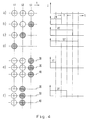
- FIG. 4 shows various operating states a) to f) for the grid times t1 to t3 and the associated ones Current pulses are shown, which are supplied to the heating element R4 at the raster time t1. Circles in the left part of the image indicate whether a printing process should be triggered at the raster times t1 to t3. An empty circle indicates that no printing process should be triggered, a hatched circle indicates that there is a printing requirement. In operating state a), no printing process is to be carried out for the raster times t1 to t3. No current pulse is supplied to the heating element R4 at the raster point in time t1. There is no preheating.
- a printing process should take place at raster time t3.
- a current pulse of constant intensity is supplied to it at the raster time t1.
- the energy content of the current pulse is set by its pulse width or duration.
- the current pulse is composed of partial pulses, each of which is a time interval T long.
- a current pulse of duration 2T composed of two partial pulses is accordingly generated and supplied to the heating element R4.
- a printing process should already be triggered at the raster time t1.
- a current pulse of duration 5T is supplied to the heating element R4.
- the heating element R4 is again subjected to a current pulse of duration 5T.
- the operating state of the heating element in which it continuously triggers printing processes, for example in order to produce a solid line on the recording medium, determines the maximum achievable printing speed of the print head 11. Since the duration of the current pulses for triggering printing processes is minimized by the method according to the invention, a high printing speed is achieved.
- the operating state of the adjacent heating elements R3 and R5, along the paths, is also taken into account when determining the energy content of the current pulse to be supplied to the heating element R4 36 and 40 (see FIG. 2) are arranged.
- the heating elements R3, R4 and R5 should each trigger a printing process. Since all three heating elements R3, R4, R5 are preheated and thus assume a higher preheating temperature than the ambient temperature Tu, less energy flows from the heating element R4 to the environment than without preheating the neighboring heating elements R3 and R5. The energy content of the current pulse to be supplied to the heating element R4 can be reduced by this amount.
- the heating element R4 is supplied with a current pulse of reduced duration 1T instead of a current pulse of duration 2T (cf. operating state b)) at raster time t1. The same happens if only one of the heating elements R3 or R4 is to trigger a printing process at raster time t3.
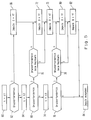
- a process flow for controlling the supply of the heating element R4 is shown schematically in a flowchart in FIG. 5. Such a procedure can e.g. by executing a program using the microprocessor 8 (see FIG. 1). In the method steps described in more detail below, the operating states shown in FIG. 4 are recognized and the associated current pulses are output
- method step 60 it is determined from the print data transmitted to print head 11 whether it is current Raster time t1 for the heating element R4 there is a pressure requirement. If this is the case, the method branches to step 66 in step 62. A partial pulse of duration 1T, ie a time interval T, is generated in this. Otherwise, proceed to method step 64. This analyzes whether there is a pressure requirement for the heating element R4 at the raster time t2. If the answer is affirmative, the method branches to step 70 in step 68 and determines whether one of the adjacent heating elements R3 or R5 or both should trigger a printing process. If this is the case, then a further partial pulse of duration 1T is generated in method step 72. Otherwise, method step 72 is omitted. In the subsequent method step 73, a partial pulse is again generated.
- step 74 It is then determined in method step 74 whether there is a pressure requirement for the heating element R4 at the raster point in time t3. If the result is positive, the method branches to step 78 in step 76. In this it is examined whether a printing process should be triggered simultaneously with the neighboring heating elements R3 or R5 or with both at raster time t3. If this is the case, a further partial pulse of duration 1T is generated in method step 80. Otherwise, step 80 is omitted and a partial pulse of duration 1T is generated in step 82.
- method step 84 If no pressure requirement has been determined in method step 76, a branch is made to method step 84 and the current pulse composed of the partial pulses generated in steps 66, 72, 73, 80 and 82 is output. This can last from 5T to 0T (empty pulse).
- Fig. 6 the control of the supply of heating elements according to the timing method is shown schematically in a block diagram.
- the heating elements of the print head 14 are electrically divided into two areas T1 and T2. They are fed with current pulses at different times via a multiplexer 92.
- the switch position of the multiplexer 92 is controlled by the microprocessor 8.
- a pulse generator 90 generates 8 current pulses depending on data from the microprocessor, which pulses are fed to the multiplexer 92.
- FIG. 7 shows the current profiles over time t for one heating element in each of the areas T1 and T2.
- the corresponding raster instants t1 and t2 are offset by 5 time intervals T, i.e. the duration of a current pulse to trigger a printing process. This results in a pulse-pause ratio or duty cycle of 50% for each area T1, T2. Since the pulse duration of a current pulse for triggering a printing process is minimal in the method according to the invention, the advantage of the high printing speed can be fully exploited when using the timing method.
Landscapes
- Electronic Switches (AREA)
Applications Claiming Priority (2)
| Application Number | Priority Date | Filing Date | Title |
|---|---|---|---|
| DE4133207A DE4133207A1 (de) | 1991-10-07 | 1991-10-07 | Verfahren zum steuern der speisung eines thermodruck-heizelements |
| DE4133207 | 1991-10-07 |
Publications (3)
| Publication Number | Publication Date |
|---|---|
| EP0536526A2 true EP0536526A2 (fr) | 1993-04-14 |
| EP0536526A3 EP0536526A3 (en) | 1993-05-26 |
| EP0536526B1 EP0536526B1 (fr) | 1997-01-22 |
Family
ID=6442201
Family Applications (1)
| Application Number | Title | Priority Date | Filing Date |
|---|---|---|---|
| EP92114645A Expired - Lifetime EP0536526B1 (fr) | 1991-10-07 | 1992-08-27 | Méthode de commande de l'alimentation d'un élément chauffant d'une imprimante thermique |
Country Status (4)
| Country | Link |
|---|---|
| US (1) | US5453776A (fr) |
| EP (1) | EP0536526B1 (fr) |
| CA (1) | CA2078182C (fr) |
| DE (2) | DE4133207A1 (fr) |
Cited By (3)
| Publication number | Priority date | Publication date | Assignee | Title |
|---|---|---|---|---|
| DE4405134A1 (de) * | 1994-02-18 | 1995-09-07 | F & O Elektronic Systems Gmbh | Vorrichtung und Verfahren zum Ansteuern der Heizwiderstände einer Thermodruckplatine zum Drucken von Grau- und/oder Farbstufen |
| EP1661716A2 (fr) | 2004-11-30 | 2006-05-31 | Francotyp-Postalia GmbH | Procédé de commande pour une tête d'impression à transfert thermique |
| US7256804B2 (en) | 2004-06-03 | 2007-08-14 | Francotyp-Postalia Gmbh | Arrangement and method for activation of a thermotransfer print head |
Families Citing this family (6)
| Publication number | Priority date | Publication date | Assignee | Title |
|---|---|---|---|---|
| DE29504576U1 (de) * | 1995-03-07 | 1995-05-11 | Francotyp-Postalia GmbH, 16547 Birkenwerder | Druckkopfthermosteuerung |
| GB9801743D0 (en) | 1998-01-28 | 1998-03-25 | Neopost Ltd | Digital print head data registration |
| US6476838B1 (en) | 1999-09-03 | 2002-11-05 | Oki Data America, Inc. | Method of driving a thermal print head |
| DE102005007220B4 (de) | 2005-02-15 | 2007-08-16 | Francotyp-Postalia Gmbh | Verfahren und Anordnung zum Steuern des Druckens eines Thermotransferdruckgeräts |
| WO2006108172A2 (fr) | 2005-04-06 | 2006-10-12 | Zink Imaging, L.L.C. | Procede d'imagerie thermique multicouleurs et element d'imagerie thermique utilise avec ledit procede |
| DE102006009334A1 (de) | 2006-03-01 | 2007-09-20 | Francotyp-Postalia Gmbh | Verfahren zur Qualitätsverbesserung des Druckens mit einem Thermotransferdruckkopf und Anordnung zur Durchführung des Verfahrens |
Family Cites Families (7)
| Publication number | Priority date | Publication date | Assignee | Title |
|---|---|---|---|---|
| JPS6067178A (ja) * | 1983-09-22 | 1985-04-17 | Fuji Xerox Co Ltd | サ−マルヘッド駆動装置 |
| JPS61239966A (ja) * | 1985-04-18 | 1986-10-25 | Fuji Xerox Co Ltd | サ−マルヘツド駆動装置 |
| US4820653A (en) * | 1988-02-12 | 1989-04-11 | American Telephone And Telegraph Company | Technique for fabricating complementary dielectrically isolated wafer |
| CA1338222C (fr) * | 1988-02-15 | 1996-04-02 | Satoshi Iwata | Methode et appareil servant a alimenter la tete d'une imprimante thermique |
| US4859093A (en) * | 1988-03-21 | 1989-08-22 | Kroy Inc. | Pixel preheat system for an automated thermal transfer device |
| DE3833746A1 (de) * | 1988-09-30 | 1990-04-05 | Siemens Ag | Thermodruckverfahren mit vorheizung |
| JPH0667179A (ja) * | 1992-06-19 | 1994-03-11 | Canon Inc | バックライト装置及び該バックライト装置を用いた表示装置並びに表示システム |
-
1991
- 1991-10-07 DE DE4133207A patent/DE4133207A1/de not_active Withdrawn
-
1992
- 1992-08-25 US US07/935,842 patent/US5453776A/en not_active Expired - Lifetime
- 1992-08-27 DE DE59207937T patent/DE59207937D1/de not_active Expired - Lifetime
- 1992-08-27 EP EP92114645A patent/EP0536526B1/fr not_active Expired - Lifetime
- 1992-09-14 CA CA002078182A patent/CA2078182C/fr not_active Expired - Lifetime
Cited By (4)
| Publication number | Priority date | Publication date | Assignee | Title |
|---|---|---|---|---|
| DE4405134A1 (de) * | 1994-02-18 | 1995-09-07 | F & O Elektronic Systems Gmbh | Vorrichtung und Verfahren zum Ansteuern der Heizwiderstände einer Thermodruckplatine zum Drucken von Grau- und/oder Farbstufen |
| DE4405134C2 (de) * | 1994-02-18 | 1999-07-08 | F & O Elektronic Systems Gmbh | Vorrichtung und Verfahren zum Ansteuern der Heizwiderstände einer Thermodruckplatine zum Drucken von Grau- und/oder Farbstufen |
| US7256804B2 (en) | 2004-06-03 | 2007-08-14 | Francotyp-Postalia Gmbh | Arrangement and method for activation of a thermotransfer print head |
| EP1661716A2 (fr) | 2004-11-30 | 2006-05-31 | Francotyp-Postalia GmbH | Procédé de commande pour une tête d'impression à transfert thermique |
Also Published As
| Publication number | Publication date |
|---|---|
| DE4133207A1 (de) | 1993-04-15 |
| CA2078182A1 (fr) | 1993-04-08 |
| US5453776A (en) | 1995-09-26 |
| EP0536526A3 (en) | 1993-05-26 |
| DE59207937D1 (de) | 1997-03-06 |
| CA2078182C (fr) | 1998-08-04 |
| EP0536526B1 (fr) | 1997-01-22 |
Similar Documents
| Publication | Publication Date | Title |
|---|---|---|
| DE2540686C2 (de) | Batteriebetriebener Drucker | |
| DE3881104T2 (de) | Druckverfahren für thermische Drucker. | |
| DE3315257C2 (de) | Thermodrucker | |
| EP0352698A2 (fr) | Procédé pour obtenir une information concernant le type de la tête d'impression | |
| DE2848910A1 (de) | Antriebssystem zur steuerung der bewegung eines gliedes | |
| EP0331138A2 (fr) | Imprimante | |
| DE4438600B4 (de) | Thermodrucker | |
| DE3447511A1 (de) | Verfahren zum aufzeichnen mittels eines thermodruckers und vorrichtung dafuer | |
| EP0536526B1 (fr) | Méthode de commande de l'alimentation d'un élément chauffant d'une imprimante thermique | |
| DE60122937T2 (de) | Thermodruckkopfsteuergerät | |
| DE69122615T2 (de) | Hochgeschwindigkeitsthermodruckvorrichtung | |
| DE69008204T2 (de) | Ansteuerungsschaltkreis für den Druckkopf eines Nadeldruckers. | |
| DE2825620C2 (de) | Verfahren und Einrichtung zum Drucken von Punktmatrixzeichen durch einen Druckkopf | |
| DE69221418T2 (de) | Aufzeichnungskopfantriebsvorrichtung | |
| DE60207488T2 (de) | Verfahren und Vorrichtung zur Steuerung eines Heizelementes in einem Thermokopf | |
| DE2648828C3 (de) | Vorrichtung zum Betätigen von Elektromagneten | |
| DE69303876T2 (de) | Thermo-Druckeranordnung und Betriebsverfahren | |
| DE3814071C2 (fr) | ||
| DE3882543T2 (de) | Wärmeübertragungsdrucker mit Widerstandsband. | |
| DE3628191A1 (de) | Verfahren und vorrichtung zur informationsaufzeichnung auf einem informationstraeger mittels eines thermodruckkopfes | |
| DE69216885T2 (de) | Verfahren und Schaltkreis zur Steuerung des Wärmedruckes unter Berücksichtigung vorangegangener Wärmedruckwerte | |
| DE3337950C2 (de) | Verfahren zur Ansteuerung einer Thermodruckleiste | |
| DE2633978B1 (de) | Verfahren und Schaltungsanordnung zur Zwischenpunktausdruckung bei Punktdruckern | |
| DE3507335C2 (fr) | ||
| DE69106534T2 (de) | Thermodrucker. |
Legal Events
| Date | Code | Title | Description |
|---|---|---|---|
| PUAI | Public reference made under article 153(3) epc to a published international application that has entered the european phase |
Free format text: ORIGINAL CODE: 0009012 |
|
| PUAL | Search report despatched |
Free format text: ORIGINAL CODE: 0009013 |
|
| AK | Designated contracting states |
Kind code of ref document: A2 Designated state(s): AT BE CH DE DK ES FR GB GR IE IT LI LU MC NL PT SE |
|
| AK | Designated contracting states |
Kind code of ref document: A3 Designated state(s): AT BE CH DE DK ES FR GB GR IE IT LI LU MC NL PT SE |
|
| RBV | Designated contracting states (corrected) |
Designated state(s): CH DE FR GB IT LI |
|
| 17P | Request for examination filed |
Effective date: 19930513 |
|
| 17Q | First examination report despatched |
Effective date: 19930915 |
|
| RAP1 | Party data changed (applicant data changed or rights of an application transferred) |
Owner name: FRANCOTYP-POSTALIA GMBH |
|
| GRAG | Despatch of communication of intention to grant |
Free format text: ORIGINAL CODE: EPIDOS AGRA |
|
| GRAH | Despatch of communication of intention to grant a patent |
Free format text: ORIGINAL CODE: EPIDOS IGRA |
|
| RAP1 | Party data changed (applicant data changed or rights of an application transferred) |
Owner name: FRANCOTYP-POSTALIA AKTIENGESELLSCHAFT & CO. |
|
| GRAH | Despatch of communication of intention to grant a patent |
Free format text: ORIGINAL CODE: EPIDOS IGRA |
|
| GRAA | (expected) grant |
Free format text: ORIGINAL CODE: 0009210 |
|
| AK | Designated contracting states |
Kind code of ref document: B1 Designated state(s): CH DE FR GB IT LI |
|
| REG | Reference to a national code |
Ref country code: CH Ref legal event code: EP |
|
| REG | Reference to a national code |
Ref country code: CH Ref legal event code: NV Representative=s name: ROTTMANN, ZIMMERMANN + PARTNER AG |
|
| ET | Fr: translation filed | ||
| REF | Corresponds to: |
Ref document number: 59207937 Country of ref document: DE Date of ref document: 19970306 |
|
| GBT | Gb: translation of ep patent filed (gb section 77(6)(a)/1977) |
Effective date: 19970314 |
|
| ITF | It: translation for a ep patent filed | ||
| PLBE | No opposition filed within time limit |
Free format text: ORIGINAL CODE: 0009261 |
|
| 26N | No opposition filed | ||
| REG | Reference to a national code |
Ref country code: GB Ref legal event code: IF02 |
|
| REG | Reference to a national code |
Ref country code: CH Ref legal event code: PFA Owner name: FRANCOTYP-POSTALIA AKTIENGESELLSCHAFT & CO. Free format text: FRANCOTYP-POSTALIA AKTIENGESELLSCHAFT & CO.#TRIFTWEG 21-26#16547 BIRKENWERDER (DE) -TRANSFER TO- FRANCOTYP-POSTALIA AKTIENGESELLSCHAFT & CO.#TRIFTWEG 21-26#16547 BIRKENWERDER (DE) |
|
| PGFP | Annual fee paid to national office [announced via postgrant information from national office to epo] |
Ref country code: CH Payment date: 20110824 Year of fee payment: 20 |
|
| PGFP | Annual fee paid to national office [announced via postgrant information from national office to epo] |
Ref country code: GB Payment date: 20110819 Year of fee payment: 20 Ref country code: DE Payment date: 20110614 Year of fee payment: 20 Ref country code: FR Payment date: 20110901 Year of fee payment: 20 |
|
| PGFP | Annual fee paid to national office [announced via postgrant information from national office to epo] |
Ref country code: IT Payment date: 20110824 Year of fee payment: 20 |
|
| REG | Reference to a national code |
Ref country code: DE Ref legal event code: R071 Ref document number: 59207937 Country of ref document: DE |
|
| REG | Reference to a national code |
Ref country code: DE Ref legal event code: R071 Ref document number: 59207937 Country of ref document: DE |
|
| REG | Reference to a national code |
Ref country code: CH Ref legal event code: PL |
|
| REG | Reference to a national code |
Ref country code: GB Ref legal event code: PE20 Expiry date: 20120826 |
|
| PG25 | Lapsed in a contracting state [announced via postgrant information from national office to epo] |
Ref country code: DE Free format text: LAPSE BECAUSE OF EXPIRATION OF PROTECTION Effective date: 20120828 Ref country code: GB Free format text: LAPSE BECAUSE OF EXPIRATION OF PROTECTION Effective date: 20120826 |